Week 8 Challenge
Aim:- To calculate the loads as per IRC 6 on the pile group for the abutment & Listing all the components of the well foundation.
Given Data:-
Basic Design Detail
| Span and Cross section | Unit | |||
| 1 | C/c of exp joint | 47.5 | m | |
| 2 | C/c of bearing | 45.3 | m | |
| 3 | Dist. Of bearing to exp joint | 1.1 | m | |
| 4 | Total Deck width | 12.5 | m | |
| 5 | Carriageway width | 8.5 | m | |
| 6 | Footpath width (One Side) | 1.5 | m | |
| 7 | Width of Crashbarrier | 1 | m | |
| 8 | Width of median | 1 | m | |
| Superstructure Details | ||||
| 1 | No fo girders | 1 | ||
| 2 | Spacing of girder | 0 | m | |
| 3 | Cantilever on both sides | 0 | m | |
| 4 | Depth od superstructure | 3.259 | m | |
| 5 | Wearing coat thickness | 0.065 | m | |
| 6 | Dist. of FRL from bearing of least height | 10.9 | m | |
| 7 | Bearing thickness | 0.065 | m | |
| 8 | Pedestal thickness | 0.25 | m | |
| 9 | Bearing + pedestal thickness | 0.315 | m | |
| 10 | Type of superstructure | Box Girder type | ||
| Level | ||||
| 1 | Height of Substructure | Assumption | 6 | m |
| 2 | Finish Road Level | FRL | 215.200 | |
| 3 | Bearing Level | BRL | 212.256 | |
| 4 | Pier Cap Top level | CTL | 211.941 | |
| 5 | Pier Cap Bottom level | CBL | 210.941 | |
| 6 | Ground Level | GL | 206.950 | |
| 7 | High Flood Level | HFL | 209.941 | |
| 8 | Chainage | 165+330 | ||
| 9 | Pile Cap top Level | 204.95 | ||
| 10 | Depth of pile cap | Assumption | 1.5 | m |
| 11 | Pile Cap Bottom level | 203.45 | ||
| 12 | Clear Cover for Pile foundation | 75 | mm | |
| Material Used | ||||
| 1 | Grade of concrete | fck M | 35 | |
| 2 | Design strength of concrete | fcd | 15.63 | |
| 3 | Grade of Steel | fyk Fe | 500 | |
| 4 | Design strength of steel | fyd | 434.78 | |
| 5 | Density of RC concrete | 2.5 | ||
| 6 | Density of Wearing coat | 2.2 | ||
| 7 | Coef. Of thermal expansion of conc. | 1.2 | E-05/ c | |
| 8 | Shrinkage strain | 2 | E-04 | |
| 9 | Modulus of elasticity of Steel | Es | 200000 | Mpa |
| 10 | Modulus of elasticity of Concrete | Ecm for M35 | 32000 | Mpa |
| 11 | Mean axial tensile strength of concrete | fctm | 2.8 | Mpa |
| Water Current Data | ||||
| 1 | Max Mean velocity | 0.98 | m/s | |
| 2 | Constant "K' for the pier in the transverse direction | 0.66 | ||
| 3 | Constant "K' for the pier in the Longitudinal direction | 1.5 | ||
| 4 | % of uplift consideration | 100 | % | |
| Soil Parameter | ||||
| 1 | Angle of shear resistance | 30 | ||
| 2 | Density of dry backfill | 2 | t/m3 | |
| 3 | Density of submerged backfill | 1 | t/m4 | |
| 4 | Net SBC | 25 | t/m5 | |
| 5 | Gross SBC (LWL) | 33.42 | t/m6 | |
| 6 | Gross SBC (HFL) | 27 | t/m7 | |
| 7 | Live Load surcharge | 1.2 | m | |
| 8 | Type of soil | median | soil | |
| 9 | Coefficient of friction | 0.5 | ||
| For Material | |||
| Material | Basic Combination | Seismic Combination | |
| Concrete | 1.5 | 1.5 | |
| Steel | 1.15 | 1.15 | |
| Load On superstructure | |||
| Dead Load of Superstructure | |||
| Total weight of superstructure | = | 300 | t |
| Reaction | = | 150 | t |
| Total reaction on abutment | = | 150 | t |
| Distance between bearing & CL of abutment shaft | = | 0 | m |
| Longitudinal movement | = | 0 | t-m |
| Transverser eccentricity of Dl from C/l of abutment | = | 0 | m |
| Transverser Movement | = | 0 | t-m |
| SIDL (Excluding wearing course) | |||
| Crash barrier weight | = | 120 | t |
| Railing weight | = | 0 | t |
| Foothpath / service weight | = | 0 | t |
| Total reaction on abutment | = | 60 | t |
| SIDL ( Wearing course) | |||
| Load intensity due to wearing course | = | 0.22 | t |
| DL of wearing course | = | 150 | t |
| Total reaction on abutment | = | 75 | t |
| Substructure | |||
| Abutment | |||
| Length ( Longitudinal ) | = | 12.5 | m |
| Length ( Transverse ) | = | 2.52 | m |
| Height | = | 0.5 | m |
| Volume | = | 15.75 | m3 |
| Weight | = | 39.375 | t |
| Trapezoidal Part | |||
| Top Length | = | 12.5 | m |
| Bottom Length | = | 12.5 | m |
| Top width | = | 2.52 | m |
| Bottom width | = | 1.5 | m |
| Height | = | 0.5 | m |
| Volume | = | 12.5625 | m3 |
| Weight | = | 31.40625 | t |
| Total weight of pier cap | = | 70.78125 | t |
| Abutment Shaft | |||
| Length ( Longitudinal ) | = | 12.5 | m |
| Length ( Transverse ) | = | 1.5 | m |
| Height | = | 6 | m |
| Volume | = | 112.5 | m3 |
| Weight | = | 281.25 | t |
| Live Load | ||||
| 1 lane 70 R wheeled | ||||
| Live Load reaction' | ||||
| Total live load | = | 100 | t | |
| No of lanes | = | 2 | nos | |
| % reduction in live load | = | 0 | % | reduction |
| impact factor - | = | 1.09 | As per IRC 6 | |
| Total load with imact | = | 109 | ||
| Ra | = | 99.3 | t | |
| Rb | = | 9.69 | t | |
| vertical reaction on the abutment | = | 99.3 | t | |
| Breaking force | = | 19.86 | t | 20 % of Ra |
| Total horizontal force at abutment | = | 9.93 | t | Fh/2 |
| Breaking Type | = | POT CUM PTFE | ||
| Transverse eccentricity | = | 3.155 | m | |
| Transverse movement | = | 313.2915 | t-m | |
| 1 lane Class A | ||||
| Live Load reaction' | ||||
| Total live load | = | 55.4 | t | |
| No of lanes | = | 2 | nos | |
| % reduction in live load | = | 0 | % | reduction |
| impact factor - | = | 1.09 | As per IRC 6 | |
| Total load with imact | = | 60.386 | ||
| Ra | = | 36.67 | t | |
| Rb | = | 23.72 | t | |
| vertical reaction on the abutment | = | 36.67 | t | |
| Breaking force | = | 7.334 | t | 20 % of Ra |
| Total horizontal force at abutment | = | 3.667 | t | Fh/2 |
| Breaking Type | = | POT CUM PTFE | ||
| Transverse eccentricity | = | 4.2 | m | |
| Transverse movement | = | 154.014 | t-m | |
| Summary Force at footing bottom level | |||||||
| Load Item | P | Load (Min) | ML | MT | HL | HT | |
| t | t | t-m | t-m | t-m | t-m | ||
| Dead Load | 150 | 0 | 0 | 0 | 0 | 0 | |
| SIDL ( Exclding wearing coat) | 60 | 0 | 0 | 0 | 0 | 0 | |
| SIDL ( wearing coat) | 75 | 0 | 0 | 0 | 0 | 0 | |
| Class 70 R vehical | 99.3 | 9.69 | 99.3 | 313.2915 | 9.93 | 0 | |
| Class A vehical | 36.67 | 23.72 | 36.67 | 154.014 | 3.667 | 0 | |
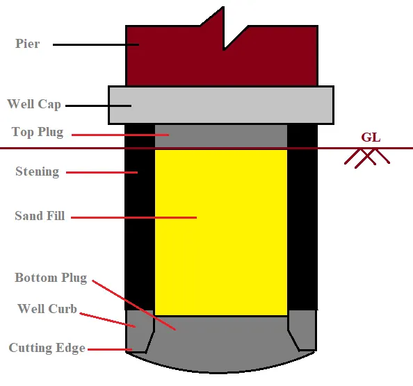
Component of well foundation and functionality in respect to bridge loading and a sketch of the same:
Well Foundation:-
A type of foundation where a part of the structure is hollow, which is generally built-in parts and sunk through ground or water to the prescribed depth by removing earth through a dredge hole.
Components of well foundation.
- Well Cap
- Top plug
- Stening
- Bottom plug
- Well curb
- Cutting edge
- Filling inside ( Sand / Water )
1) Well Cap.
A well cap is an RCC slab structure that is located below the pier/ abutment and above the well, The well cap contributes the required surface for positioning the pier or abutment and transfers its loads safely to the well foundation.
2) Top plug
It is a PCC filling which is filled above the sand filling which is located inside the well foundation it is 300 mm thick above the sand filling.
3) Stening
Wall of the well foundation is called as stening it is made up of RCC.
The thickness of steining is determined based on the following considerations:
- It should not be extremely thick so that unnecessary resistance is avoided during the sinking of the well.
- It should not be extremely thin so that it gets destroyed either during the sinking of the well or under design loads. The stresses generated in the steining should be within permissible limits under design loads.
- The steining should resist the more stresses generated when corrective measures are taken for tilting and shifting of the well.
Finite element method is use to design the well foundation.
4) Bottom plug
After successful sinking is done then we have to provide PCC fill at the bottom level in the well foundation bottom plug increase the bearing resistance and gives long term stability to well foundation.
cement content is use in bottom plug is 330 kg/m3 and provide thickness as 300 mm.
5) Well Curb.
Well curb is loacated below the stening which is use to transfer all the load from top to the soil throught the cutting edge while sinking.
It is made up of RCC. and integral angle should be kept in between 30 to 37 degree. and grade of concrete is use M25. with 72 kg/cm reinforcement.
6) Cutting Edge.
The lowest part of the well foundation is cutting edge and it enables penetration of the bottom of the well during the sinking.The thickness of the cutting edge and the slope angle of the inside edge should be such that it should be sharp sufficiently for easy sinking, and at a similar time should not break when penetrating through the hard rock or soil.
7) Filling
After completion construction of well foundation we have to fill filling insing the foundation to give stability to the structure it is either sand or water.
Sketch of Well Foundation: