Week 9 Challenge
Aim:
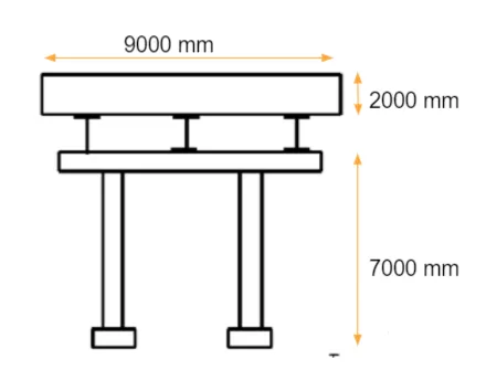
To calculate the Wave Load on the bridge superstructure shown in figure below and applying the resulting forces for modelling in StaadPro.
Additional given data:
- The maximum crest elevation for the wave = 3 m
- The deck of the slab is supported by three I Girders
- Height of Girder =1.7 m
- Top and bottom flange width = 2.5m
- The thickness of flange and web = 500 mm
- The Span of the bridge = 12m
- The width of deck slab = 9m
- Thickness of deck slab = 2m
- Constant r = 5
- Cva = 3
- The Storm elevation = 8.5m
- Cr = 0.4
Introduction:
Waves are caused by a disturbance in the water surface. They develop due to disturbances like winds, boat or ship movement, or other forces such as underwater landslides due to Earth quakes (Tsunamis). When the wind blows over the sea, waves occur according to the intensity of the wind and generate a force on bridge substructure like piers and abutments. This is accounted as wave loads in the design of substructure for designing bridges in the sea. This wave will try to erode the soil around the piers. Foundation gets damaged and pier or abutment tends to rotate.
Failure occurs when the wave induced loads on the deck of the coastal bridges exceed the capacity resulting in partial removal or complete collapse of bridge decks.
Wave induces varying loads and are calculated in terms of vertical and horizontal loads
- (Fv)max = (Cva-v) Fv*
- (Fh)max = [1+Cr(N-1)](Cva-h)Fh*
Where,
(Fv)max = Maximum of vertical wave induced load
(Fh)max = Maximum of horizontal wave induced load
Fv* = Reference vertical load
Fh* = Reference horizontal load
Cva-v = Empirical coefficient for vertical varying load
Cva-h = Emperical coefficient for horizontal verying load
Cr = Reduction coefficient for reduced horizontal load on the interval girders
N = Number of girders supporting the bridge deck
Fv* = gama x ΔZv x Av
Av = Area of bridge contributing to vertical uplift i.e., projection of bridge deck onto horizontal plane
ΔZv = Difference between elevation of crest of maximum wave and elevation of underside of bridge deck
gama = unit weight of water
Fh* = gama x ΔZh x Ah
Ah = Area of bridge contributing to vertical plane
ΔZh = Difference between elevation of crest of maximum wave and elevation of the centroid of Ah
gama = unit weight of water
For significant wave height (Hs), this elevation can be calculated as follows:
- ηmax ~ (0.8)(1.67)Hs = 1.3 Hs
Procedure
Manual Calculation:
Fv* = gama x ΔZv x Av
Fv* = 10 x 8.5 x (9 x 12) = 9180 kN
Fh* = gama x ΔZh x Ah
Fh* = 10 x (8.5 + (1.7+2)/2) x (3.7 x 12) = 4595.4 kN
(Fv)max = (Cva-v) x Fv*
(Fv)max = 3 x 9180 = 27540 kN
(Fh)max = [1+ Cr (N-1)] (Cva-h) Fh*
(Fh)max = [1+0.4 x (3-1)] x 3 x 4595.4 = 24815.16 kN
Design in StaadPro:
Based on the above calculated values, we begin our design using the data provided.
Modelling
- Deck slab with I girders and cross beams is modelled. Span of 12m and deck width of 9.0m having 3 I girders of the sizes provided to us.
- Peir of height 7.0m is modelled as per data provided. Fixed supports are assigned at the bottom of piers indicating the foundation by selecting the option General > Supports > Fixed > Add> assign to selected nodes.
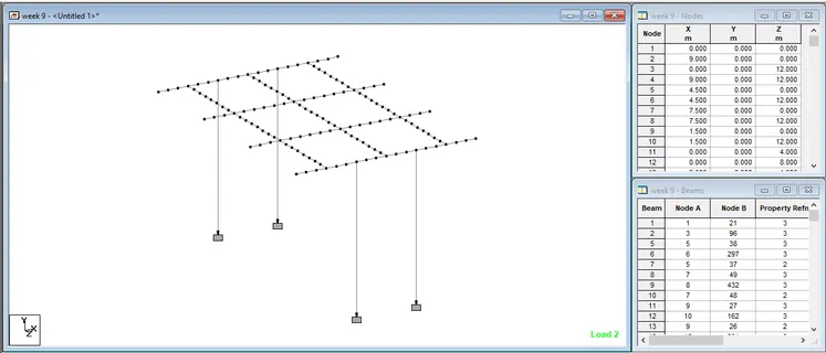
- Mesh of size 0.5 x 0.5 is modelled using plate cursor representing the deck slab.
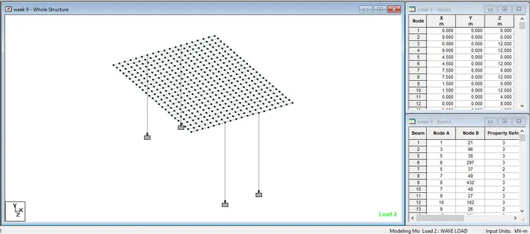
Specifications
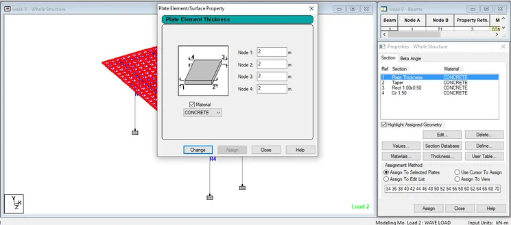
- Properties are assigned using General > Properties> Plate thickness > 2.0m, Material : Concrete > Add > assign to selected plates of deck slab.
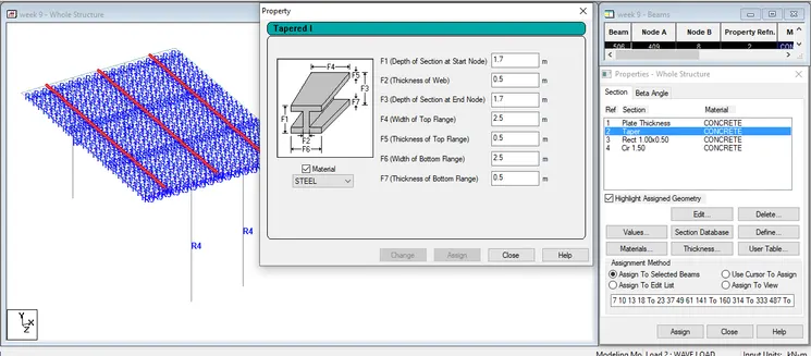
- For I girders, Section of an I girder are deifined as General > Properties> Define> Tapered I > (specified as under) > Material: Concrete> Add > assign to selected beams of main girders.
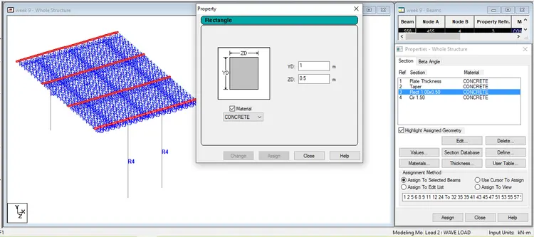
- Cross beams of size (0.5x1.0)m are assumed and is assigned as General > Properties > Define > Rectangle > YD: 1.00 m, ZD:0.5 m -> Material: Concrete > Add > Assign to selected beams for Cross girders.
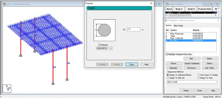
- Circular Peirs of size 1.5m diameter are assumed and assigned as General > Properties > Define > Circular > YD: 1.50 m > Material: Concrete > Add > Assign to selected beams for Piers.
Loading
We begin loading from the loading tab
- Loads & Definition > Load case details > Add > Change Load case 1 as SW > Type : Dead load > Add
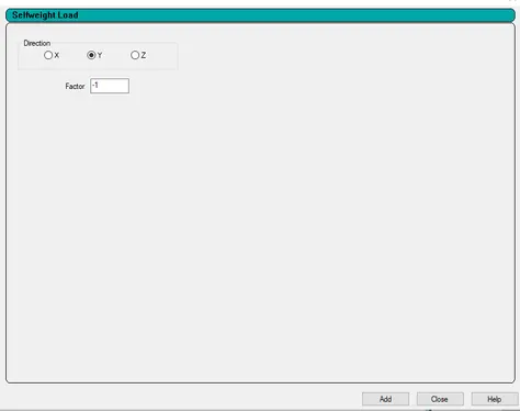
- SW > Add > Self weight load > -1 > Add
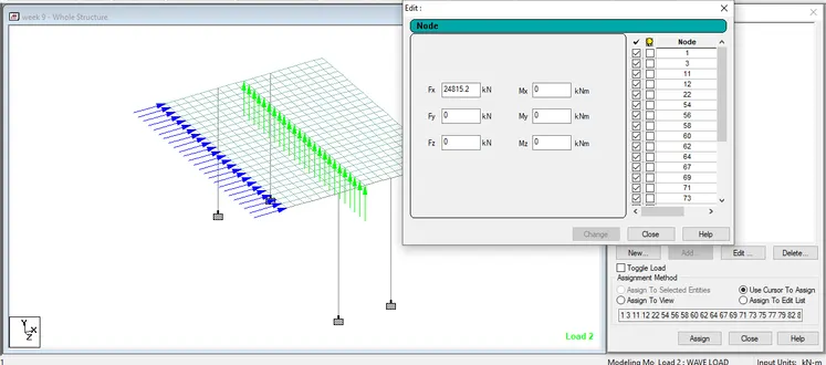
- General > Loads & Definition > Load case details > Add > Change Load case 2 as Wave load > Type : Live load > Add
- Wave load > Add > Nodal load > FX = 24815.16 kN > Add [(Fh)max as calculated above]
- Wave load > Add > Nodal load > FY = 27540 kN > Add [(Fv)max as calculated above]
Analysis
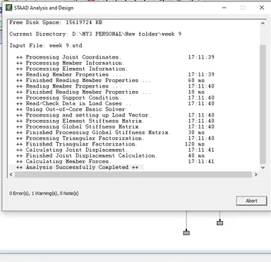
Analyze > Perform Analysis
Analyze > Run Analysis
Results
- After correcting errors occured in Analysis, we go to post processing to view the results of Bending moment, shear force, stresses in all the structural elements.
- Bending Moment Mz in kNm in Main girders are shown in the figure below.
Maximum bending is obtained by selecting the main girders,
Click Report > section forces > Mz > sort : low to high (for sagging moment) > OK
BM max = -82.276 Mton-m which is in the beam number 62 for Wave Load
Click Report > section forces > Mz > sort : high to low (for hogging moment) > OK
BM max = 10717 Mton-m which is in the beam number 149 for Wave Load
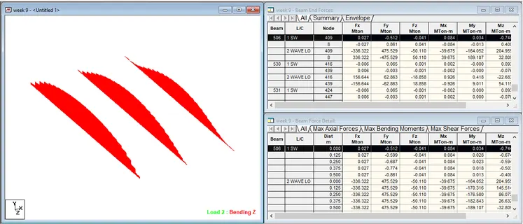
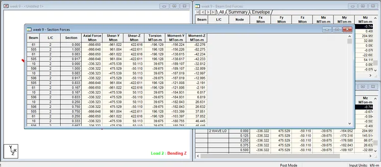
Shear force Y in kN in Main girders are shown in the figure below.
Maximum Shear force is obtained by selecting the main girders,
Click Report > Section forces > Shear Y > OK
SF max = 1371 Mton which is in the beam number 330 for Wave Load
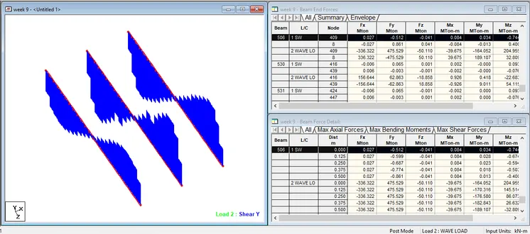
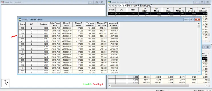
Bending Moment Mz in kNm in Cross girders are shown in the figure below.
Maximum bending is obtained by selecting the cross girders,
Click Report > Section forces > Mz > sort : low to high (for sagging moment) > OK
BM max = -9306.8 Mton-m which is in the beam number 238 for Wave Load
Click Report > Section forces > Mz > sort : high to low (for hogging moment) > OK
BM max = 7274 Mton-m which is in the beam number 385 for Wave Load
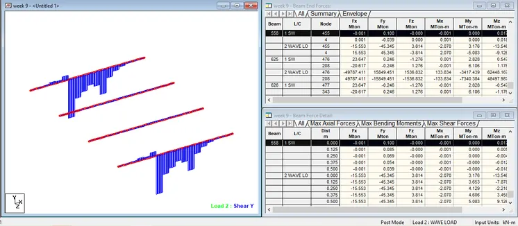
Shear force Y in kN in Cross girders are shown in the figure below.
Maximum Shear force is obtained by selecting the cross girders,
Click Report > Section forces > Shear Y > OK
SF max = 15239 Mton which is in the beam number 238 for Wave Load
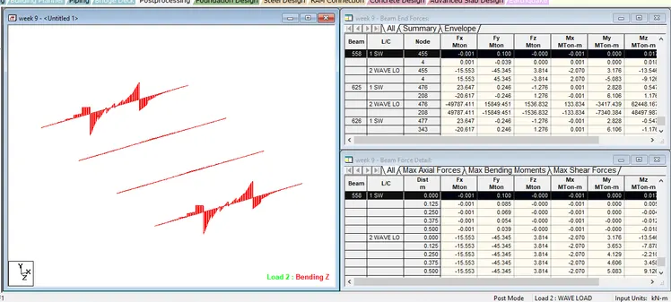
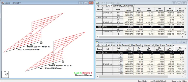
Bending Moment Mz in kNm in Piers are shown in the figure below.
Maximum bending is obtained by selecting the Piers,
Click Report > section forces> Mz > sort : low to high (for sagging moment) > OK
BM max = -48497 Mton-m which is in the beam number 625 for Wave Load
Click Report > Section forces> Mz > sort : low to high (for sagging moment) > OK
BM max = 62448 Mton-m which is in the beam number 625 for Wave Load
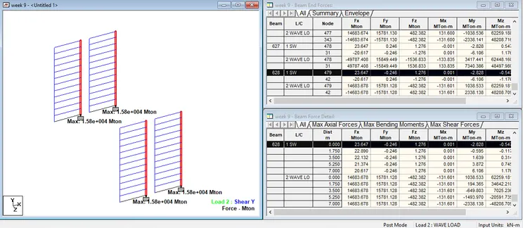
Shear force Y in kN in Piers are shown in the figure below.
Maximum Shear force is obtained by selecting the Piers,
Click Report > Section forces > Shear Y > OK
SF max = 15849 Mton which is in the beam number 625 for Wave Load
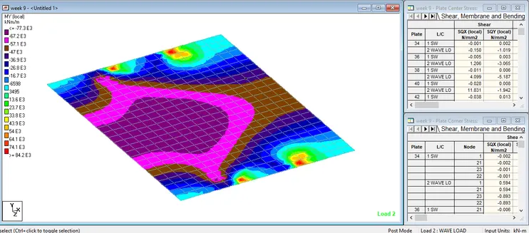
Stresses in plate for deck slab is obtained by using the option,
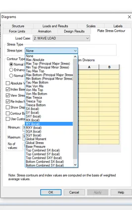
Select all plates, Post procesing > plates > contour > MY > apply > OK
Similarly for MX
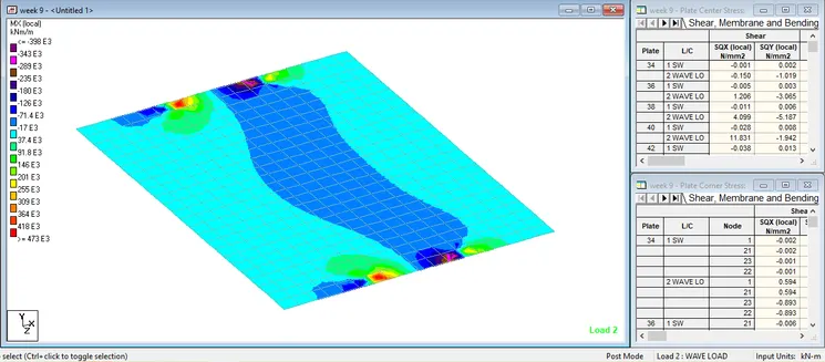
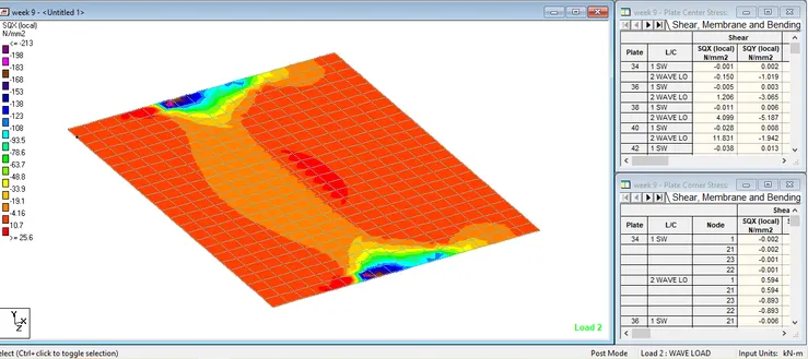
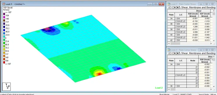
It is observed that the most amount of stresses are concentrated near start and end of the deck slab.
SQx and SQy denotes shear force in X and Y directions of a plate for Deck Slab.