Project 2
Aim
To create a Bridge Structure and calculate the Water Current Forces, Centrifugal Forces, Wave Forces, Snow Loads, Temperature Loads and Barge Impact Load and applying the same on the StaadPro Model.
Data Provided:
- Crest elevation wave = 3.0m max
- 4 - I girders
- r = 5
- Cva = 3
- Storm elevation = 8.5m
- Cr = 0.4
- 70RT vehicle
- Radius of curvature = 2.0m
- Design speed of vehicle Vd = 50km/hr
- Pier size = 1.2 x 1.2 m
- Deck slab width = 10.5 m
- Thickness of deck slab = 1.5m
- Flat bridge with `beta`<30 deg
- Depth of snow accumulation = 1.25m
- HFL = 4.0m above bottom foundation level
- Span = 10 m
- Mean velocity = Vmean = 2.5 m/s
- Carriage width = 9.0m
- DW of Panamax vessel = 25000 DWT
- Max of 1500 containers
- Each container = 6.1 TEU
Introduction to Various Loads
1. Water Current Forces
Water current forces are the forces caused by the ocean currents. Deep ocean currents are driven by density and temperature gradients.
Major ocean currents are:
a) North Equatorial current
b) Equatorial counter current
c) Atlantic current
d) North pacific current
e) South pacific current
Different layers of water dont have same density. Water layer having higher density get settled down. Water having high temperature zone tends to move to a place of low temperature zone. Whenever there is temperature gradient between two definetly there will be movement of water to a place of low temperature zone. This generates huge force. This is called water current force. This force will increase from time to time due to change in global warming.
2. Centrifugal Forces
The moving of a vehicle in a curve produces an outward pushing force from the bridge which exerts loads on the structural elements of the bridge called as the centrifugal loads.
C = WV^2/127R
where,
C = Centrifugal force acting normal to traffic at the point of action of wheel or uniformly distributed over every length on which a udl acts in tonnes
W = Live load in case of wheel loads, each load being considered as acting over the ground conact length specified un clause 204 in tonnes or Live load in case of uniformly distributed Live load in tonne/m linear
V = Design speed of vehicle using bridge in km/hr
R = Radius of curvature in m
3. Wave Forces
Waves are caused by a disturbance in the water surface. They develop due to disturbances like winds, boat or ship movement, or other forces such as underwater landslides due to Earth quakes (Tsunamis). When the wind blows over the sea, waves occur according to the intensity of the wind and generate a force on bridge substructure like piers and abutments. This is accounted as wave loads in the design of substructure for designing bridges in the sea. This wave will try to erode the soil around the piers. Foundation gets damaged and pier or abutment tends to rotate.
Failure occurs when the wave induced loads on the deck of the coastal bridges exceed the capacity resulting in partial removal or complete collapse of bridge decks.
Wave induces varying loads and are calculated in terms of vertical and horizontal loads
- (Fv)max = (Cva-v) Fv*
- (Fh)max = [1+Cr(N-1)](Cva-h)Fh*
Where,
(Fv)max = Maximum of vertical wave induced load
(Fh)max = Maximum of horizontal wave induced load
Fv* = Reference vertical load
Fh* = Reference horizontal load
Cva-v = Empirical coefficient for vertical varying load
Cva-h = Emperical coefficient for horizontal verying load
Cr = Reduction coefficient for reduced horizontal load on the interval girders
N = Number of girders supporting the bridge deck
Fv* = gama x ΔZv x Av
Av = Area of bridge contributing to vertical uplift i.e., projection of bridge deck onto horizontal plane
ΔZv = Difference between elevation of crest of maximum wave and elevation of underside of bridge deck
gama = unit weight of water
Fh* = gama x ΔZh x Ah
Ah = Area of bridge contributing to vertical plane
ΔZh = Difference between elevation of crest of maximum wave and elevation of the centroid of Ah
gama = unit weight of water
For significant wave height (Hs), this elevation can be calculated as follows:
- ηmax ~ (0.8)(1.67)Hs = 1.3 Hs
4. Snow Loads
Snow load is calculated as per IS 875 Part-IV and the loads are applied in accordance with IRC 6. Minimum snow load that is considered for deisgn of bridges is 900kg/m^3 as per clause 224 of IRC 6.
Snowy regions in India are, Jammu & Kashmir, Himachal Pradesh, Uttarakhand, Haryana, West Bengal, Arunachal Pradesh, Assam, Manipur, Meghalaya.
Calculation of Snow Load as per IS 875 Part-IV
- Design snow load S = μ S0
where,
μ= shape coefficient
S0 = Snow load on ground
In most regions, snowfall is accompanied or followed by wind. The wind will redistribute the snow. In multi level roofs, the accumulated drift load may reach a value that is a multiple of the ground load.
5. Temperature Loads
The daily and seasonal fluctuations in air temperature, solar radiations etc causes the following:
- Effective bridge temperature : Changes in overall temperature of bridge.
- After a period, there will be a minimum and maximum with a range of effective bridge temerature.
- This results in load and load effects.
The load effects are due to:
- Temerature restraints : Restraints offered for expansion or constraction by form of construction.
Eg. Portal frame, arch, flexible pier, elastometric bearings etc.
- Frictional bearing restraint : Friction at roller or sliding bearings
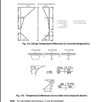
- Temperature difference: Difference in temperature between the top surface and other levels through the entire height of the superstructure.
- Positive Temperature difference : During solar radiations, gaining heat on top surface of superstructure.
- Reverse temperature difference : Loss of temperature on top surface of superstructure as a result of radiation and other effects.
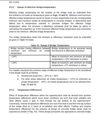
As per IRC 6-2016, table 15, shows the range of bridge temperature as illustrated below.
For the purposes of calculating temperature effects, the coefficient of thermal expansion
for RCC, PSC and steel structure may be taken as 12.0 x 10⁻⁶/deg C.
Tensile stresses resulting from temperature effects not exceeding in the value of 2/3rd of modulus of rupture may be permitted.
Sufficient amount of non tensioned steel shall be provided to control thermal cracking.
6. Barge Impact Load
Bridges crossing navigable channels of rivers, creeks and canal as well as shipping channels in port areas and open areas can be provided with navigable spans. Navigation spans shall be specifically identified and marked to direct waterway traffic below them.
1. The following should be decided based on the classification of waterways as per Inland waterways Authority of India (IWAI) or the concerned ports or shipping authorities:
- Span arrangements
- Horizontal clearances between the inner face of piers within thw width of navigation channel.
- Vertical clearances above the air-draft of the ships/ barges upto soffit of deck
- Minimum depth of water in the channel below the maximum laden draft of barges.
2. Bridge components located in a navigable channels of rivers and canals shall be designed for barge impact force due to possibilityof barge accidentally colliding with the structure.
3. For bridges located in sea and waterways under control of ports
Bridge components should be designed for vessel collision forces.
- Ship / barge details can be obtained fromconcerned authority.
- Specialist literature may be referred for magnitudes of design forces and appropriate design solutions
4. Design objectives of the bridges:
- To minimise the risk of structural failure of bridge component due to collision with a plying barge in a cost-effective manner.
- Reduce the risk of damage to the barge and environmental pollution
5. Localised repairable damage of substructure and super structure components is permitted provided that
- Damaged structural components can be inspected and repaired in a relatively cost effective manner not involving detailed investigation
- Sufficient ductility and redundancy exist in the remaining structure to prevent consequential progressive collapse in the event of impact.
Procedure for Manual Calculation and Modelling in StaadPro
We begin by creating a New Project named "Project 2" on StaadPro.

Step 1: Modelling
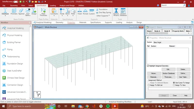
First Create a model in STAAD.Pro using Translational repeat command.
Step 2: Assigning Supports
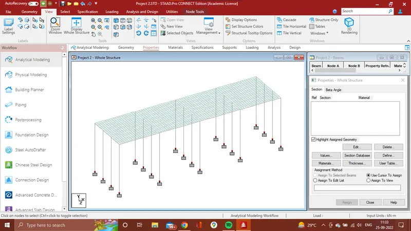
Now, we need to assign the supports to the Piers.
For that, following are the steps.
- Go to Specification > Fixed > Support 2 > Select all buttom node of the structure > Assign to selected node > Assign > Yes
Step 3: Specifications
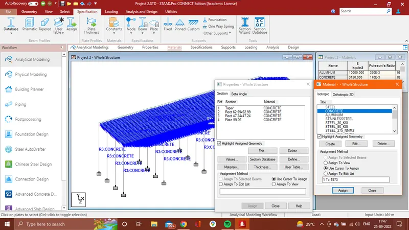
Assigning Property to each element.
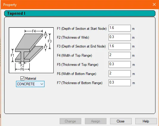
The property for the longitudinal I girders is being shown below. The data entered is as per given data.
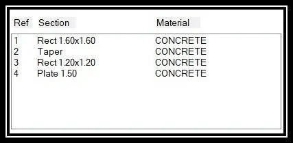
Similarly, properties for Cross Girders, Piers and Deck Slab are given below as per data provided.
For Assigning Beam element property
- Specification > Prismatic > In property window select suitable Property > Enter dimensions of Property as given > Select property > Select Element > Assign to selected beam > Assign.
For Assigning Plate element property
- Specification > Plate Thickness > Size of the plate > Add > Select plate property > Select plate property and then select plate element > Assign to selected plate > Assign.
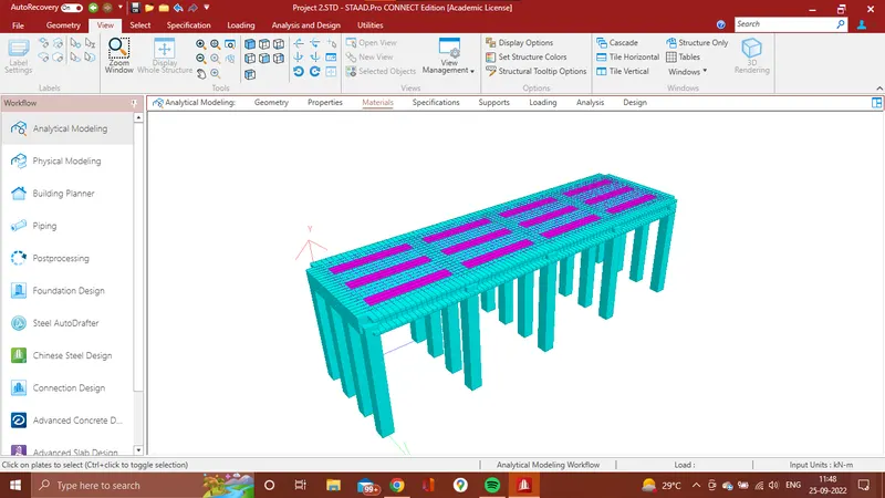
3D Rendered Model
Step 4: Loading
1. Water Current Load.
Given Data
The mean velocity of the river is 2.5 m/s.
The high flood level is 4 m.
For Calculation Of Water Current Load formula is given in IRC 6 which is P=52K`V^2`
Where,
P = Intensity Of pressure due to water current, in kg/`m^2`
V = The veloecity of the current at the point where the pressure intensity is being calculated, in meter per second and
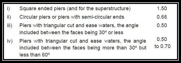
K = A constant having the following value for different shapes of piers illustrated .
We Consider the rectangular pier so value of K is 1.50 as given in below table.
Solution,
The height of pier subjected to water current H = 4 Meter
Maximum Velocit, V = `sqrt 2` X Vmean
= `sqrt 2` X 2.5
= 3.54
Water Current, P = 52 X K X `V^2`
= 52 X 1.50 x `3.54^2`
= 977.46 kg/`m^2`
We need to convert the value of P in Kilonewton.
Total Water Current Load acting on pier is 9.58 kN/m
Assigning Load on structure by using staad.pro software
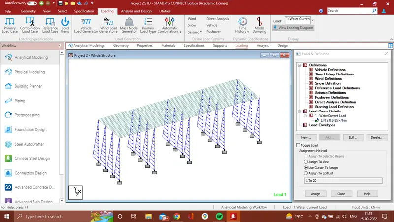
- Go to Loading > Load & Definition > Load Cases Detail > Case 1 as Water Current Load > Add
- Water Current Load > Add > Member Load > Linear Variying > W1 = 0, W2 = 9.85 > Direction Z (local) > Add > Select pier then select Load >Assign to selected beam > Assign.
2. Centrifugal Load.
Given Data
The design speed of the vehicles is 50 km/hr.
The bridge is subjected to a live load of Class 70R tracked vehicle.
Radius of curvature in the bridge is 2 m.
Centifugal force C = WV^2/127R
Where,
C = Centrifugal force acting normally to the traffic (1) at the point of action of the wheel loads or (2) uniformly distributed over every metre length on which a uniformly distributed load acts, in tonnes.
W = Live load (1) in case of wheel loads, each wheel load being considered as acting over the ground contact length specified in Clause 204, in tonnes, and (2) in case of a uniformly distributed live load, in tonnes per linear metre
V = The design speed of the vehicles using the bridge in km per hour, and.
R = Radius of Curvature.
Solution,
Centrifugal Force C = `frac{700 X (50)^2}{127 X 2}`
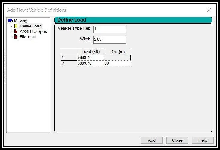
= 6889.76 kN
Centrifugal Load acting on structure is 6889.76 kN.
Applying Load on structure using software
- Loading > Load & Definition > Definitions > Vehicle Definition > Add > Adding Calculated value > Add
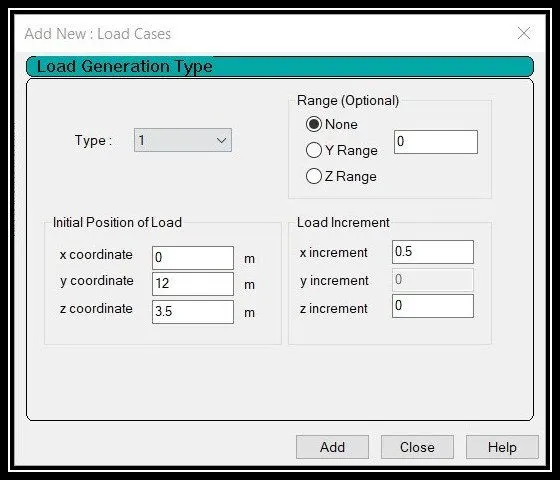
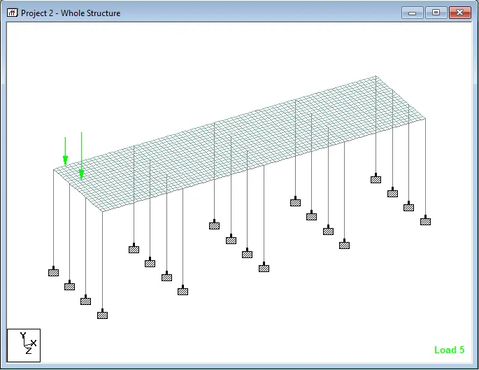
- Load & Definition > Load Case Details > Load Generation > No of load to be generated (81 Nos) > Add
- GENERATED LOAD > Add > Enter relevant co-ordinates as shown below and provide increment in the direction desired > Add
3. Wave Load
Given Data
The maximum crest elevation for the wave is 3 m.
Constant r as 5.
Assume Cva as 3 & Cr as 0.4.
The Storm elevation is 8.5 m.
Each I Girder is 1.6 m height with a top and bottom flange width of 2 m.
We have to do calculation for wave load from IS 4651 Code
All the value we have to consider from this code.
Solution,
1. Fv = `gamma` X `Delta zv` X Av
= 10 X 1.9 X 420
= 7980 kN
2. Fh = `gamma` X `Delta zh` X Ah
= 10 X 1.7 X 104
= 1768 kN.
`**` Fv max = Cva-v Fv
= 3 X 7980
= 23940 kN
= `frac{(Fvmax)}{Av}`
= `frac{23940}{420}`
= 57 kN
`**` Fhmax = [ 1 + Cr (N-1) ] Cva-h X Ah
= [ 1 + 0.4 ( 4 - 1)] 3 X 1768
= 11668.8 kN
= `frac{Fhmax}{Ah}`
= `frac{11668.8}{104}`
= 112.2 kN
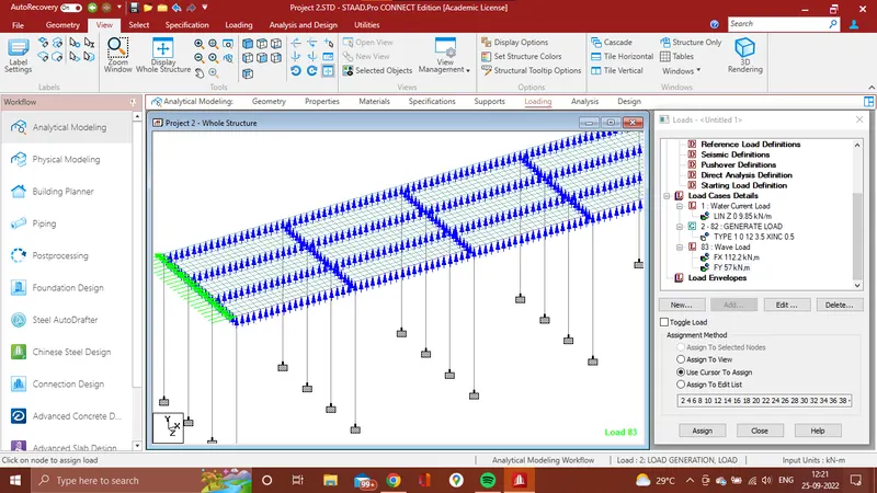
Total Wave Load acting on structure is Fv max = 57 kN & Fh max = 112.2 kN.
Assigning Load on structure model in staad.pro
- Loading > Load & Definition > Load Case Details > Add > Load case as Wave load > Add.
- (For Ah) Wave Load Case > Add > Nodal Load > Fx = 112.2 kN > Add > Select Load > Assign to selected nodes > Assign.
- (For Av) Wave Load Case > Add > Nodal load > Fy = 57 kN > Add > Select Load > Assign to selected Nodes > Assign.
4. Snow Load
Given Data
The depth of accumulation of snow is 1.250 M.
The deck of bridge is flat with B <30 degree.
Assumption.
We assume settled snow so densiy of snow is 3 kN/`m^3`
Solution,
Snow Load (So)
S0 = Density Of Snow X Depth of Snow X Length of bridge
= 3 X 1.250 X 40
= 150 kN/m
Shape Of coefficient from IS 875 part 4
For angle `beta` < 30 degree , `mu` = 0.8
So,
Design Snow Load
S = `mu` X S0
= 0.8 X 150
= 120 kN/m
Snow Load acting on the deck is 120 kN/m
Snow load calculated above as per the given data shall now be assigned in the model as elaborated below
- Load & Definition > Load case details > add > Snow load > type : Live load > add
- Snow load > add > member load > -120kN/m > add > assign to selected beams > assign
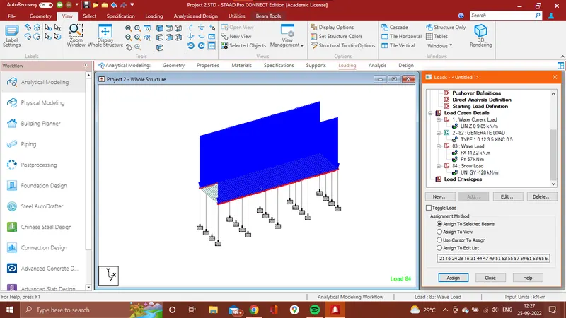
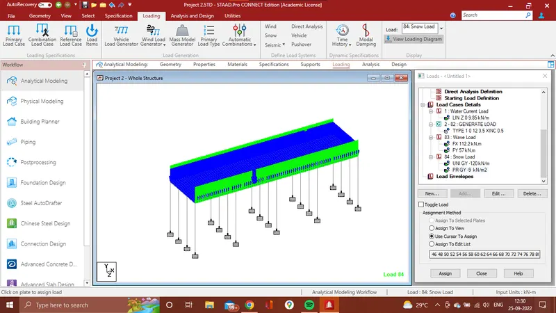
Minimum snow load considered for deisgn of bridges is 900kg/m3 as per clause 224 IRC 6 which shall be applied on the plate elements for deck slab.
- Snow load > add > plate load > -9kN/m2 > add > assign to selected plates
5. Temperature Load
Assumed Data
City we as assuming Delhi
Grade of concrete is M 40 grade.
1) Maximum temperature in the location as per IRC 6
Isotherm at the Location = 47.5 degree
2) Minimum temperature in the loaction as per IRC 6
Isotherm at the loacation = -2.5 degree.
`**` Effective temperature dfference
`Delta T` = `frac{47.5 - (-2.5)}{2} + 10`
= 25 + 10
= 35 degree.
`**` Stress due to tempereture = `alpha` X `Delta T` X E
Where,
`alpha` is coefficient of thermal expansion is reinfoeced concrete is taken as 11.27 X `10^-6` degree per centrigrade.
`Delta T` is Effective temperature difference.
E is Modulus of elasticity of material
= 11.27 X `10^-6` X 35 X 5000 `(40)^frac{1}{2}`
= 12.47 kN/`m^3`
`**` Maximum permissible stress
= `(2/3)` X 0.7 X `sqrt fck`
= `2/3`X 0.7 X `(40)^frac{1}{2}`
= 2.95 kN/`m^2`
Hence,
The stress are restricted to 3 kN/`m^2`
- Maximum temperature = 47.5 degree
- Minimum temperature = -2.5 degree.
Positive temperature difference
- Temperature at top = 47.5 degree
- Temperature at buttom = `(2.1/17.8)` X 47.5
= 5.60 degree.
Temperature at top is 47.5 degree and buttom temperature is 5.60 degree.
Assigning Load in software
- Loading > Load Case detail > Add >Case as Temperature Load > Add.
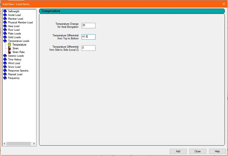
- Temperature Load > Add > Temperature Load > Temperature > Temperature change for axial elogation = 35 , Temperature difference from top to buttom = 41.5, > Add
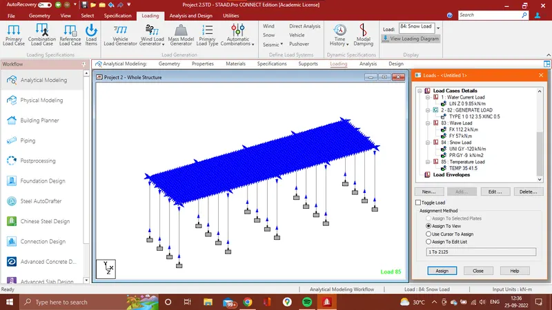
- Select Temperature load > Assign to view > Assign.
6. Barge Impact Load.
Given Data
The Dead weight tonnage of Panamax vessel is 25000 DWT (W).
Assumption,
Velocity we consider 50 kM/hr = 13.89 m/sec (V)
CH = 1.25
`**` Barge Collision enegry 'KE'
= 500 X CH X W X `(V)^2`
= 500 X 1.25 X 25000 X `(13.89)^2`
= 3014564063
`**` Barge damage depth 'aB'
= 3100 X ( [ 1 + 1.3 X `10^(-7)` X KE ]0.5 - 1 )
= 3100 X ( [ 1 + 1.3 X `10^(-7)` X 3014564063 ] 0.5 -1 )
= 58346.76 mm
`**` Barge Collision Impact force 'Pb'
For aB > 100 mm , Pb = 6.0 X `10^6` + 1600 X (aB)
= 6.0 X `10^6` + 1600 X (58346.77)
= 99354832 N
Uniform force,
= Pb / Lenght Of Bridge
= `99354832.861/40`
= 2483870.822 N
= 2483.87 kN/m
Barge Impact Load on Structure is 2483.87 kN/m
Assing Load on Stucture By using STAAD.Pro Software.
- Loading > Load Cases Detail > Add > Case as Barge Impact Load > Add.
- Barge Impact Load > Add > Member Laod > Uniform force > W1 = 2483.87 kN/m , Direction as GZ > Add
- Select Load > Assign to selected beam > Assign
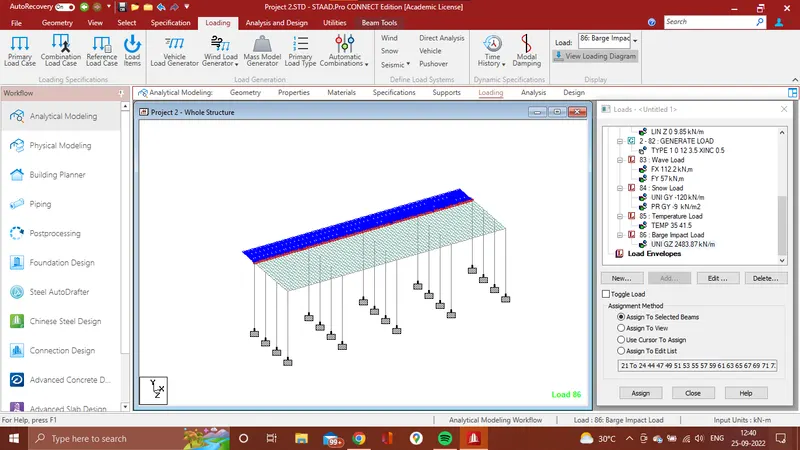
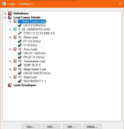
A Summary of Loads Assigned on Structure in addition to Vehicle Generated Loads of 81 nos is shown below.
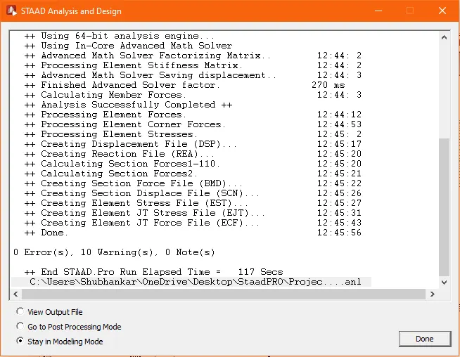
Step 5: Analysis
- Go to Analysis and design option.
- Click on run analysis then analysis wll start.
- After analysis this window will come
This modelling has generated zero errors.
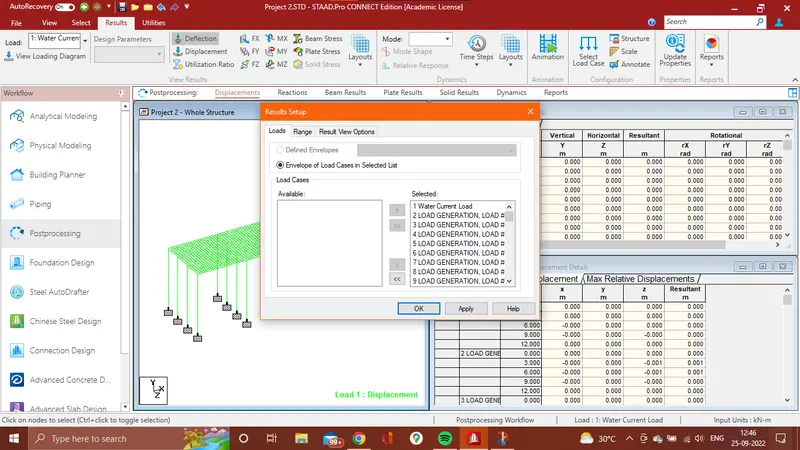
- To view the result click on Go to Post Processing Mode > Done.
- The following window will open
Step 6: Results
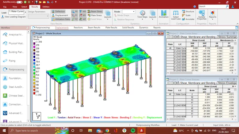
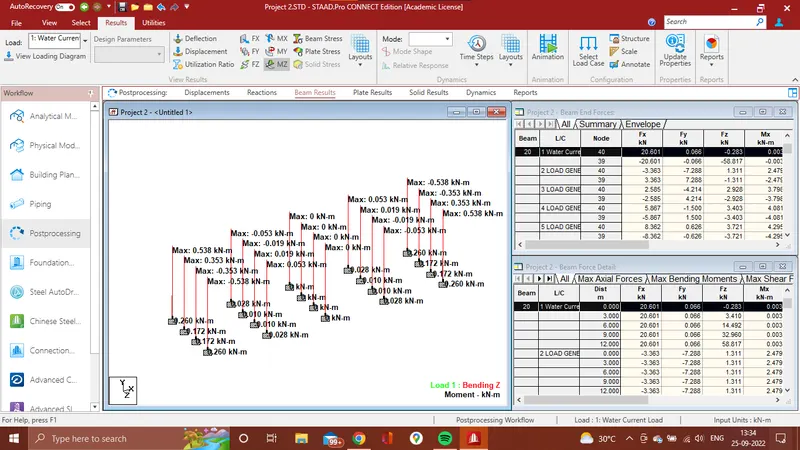
1. Water Current Loads:
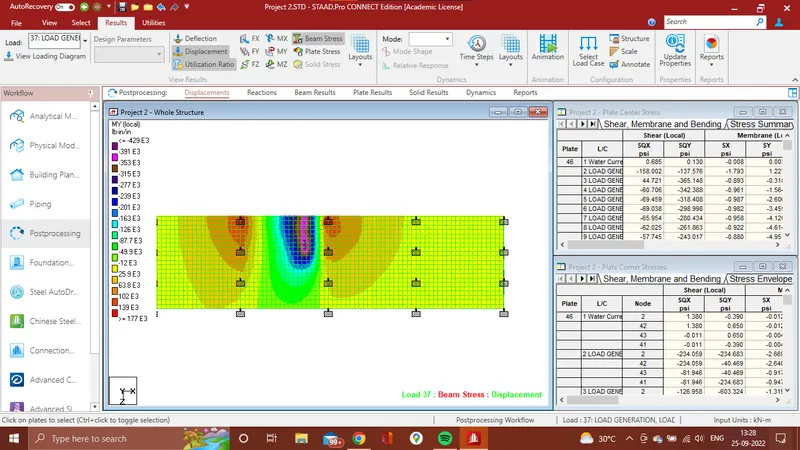
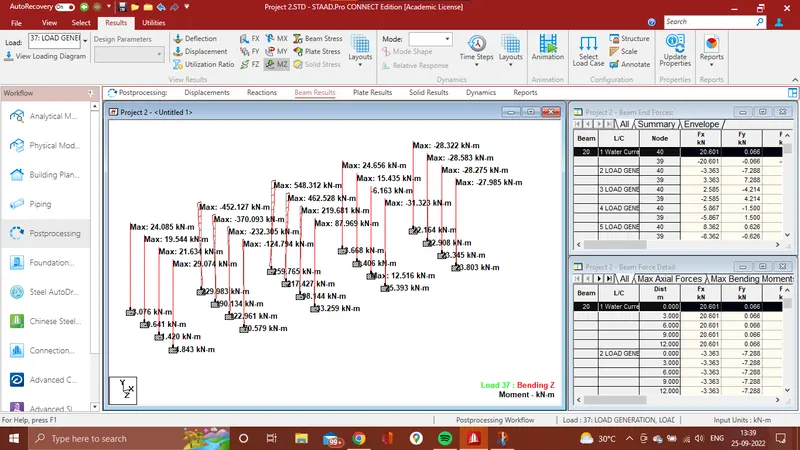
2. Centrifugal Load:
Load Generation No. 37
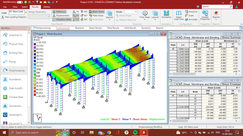
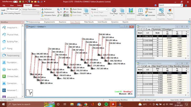
3. Wave Load:
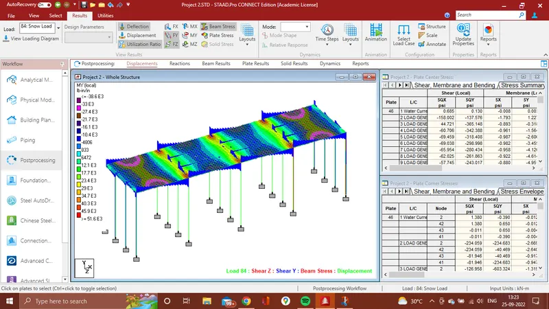
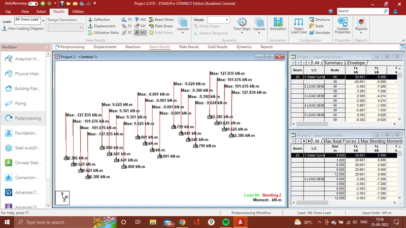
4. Snow Load:
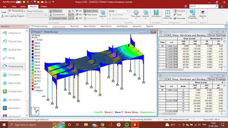
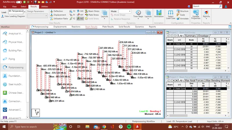
5. Temperature Load:
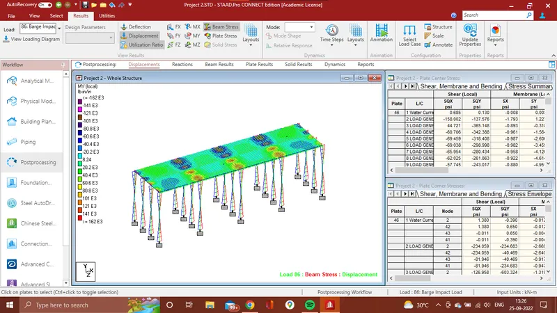
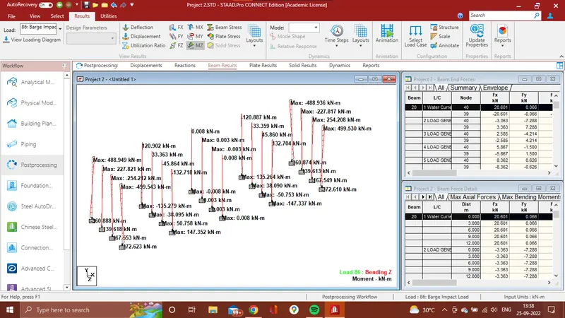
6. Barge Impact Load: