Week 2 Challenge
Aim:
The aim of the challenge is the calculation of live loads as per IRC and modeling the same in Staadpro to perform the structural analysis of the given structure.
Given:
- Width of the bridge deck is 7m ,
- Span of the bridge is 24m,
- Pier size is 2 m diameter,
- The seismic zone is Zone III,
- Wind speed is 42 km/hr,
- Unit weight of soil is 18 kN/m3
Introduction:
As per IRC:6-2017, road bridges and culverts shall be divided into classes according to the loadings they are designed to carry.
I. Types of Loading
a. IRC Class A Loading: This loading is to be noramlly adopted on all roads on which permanent bridges and culverts are constructed.
b. IRC Tracked Loading: Here there is no exact ground contact area. The entire track touched the ground when it is moving. this contact area is as per IRC.
c. IRC Class 70R Loading: This loading is to be normally adopted on all roads on which permanent bridges and culverts are constructed. Bridges desinged for Class 70R Loading should be checked for Class A Loading also as under certain conditions, heavier stresses may occue under Class A Loading.
d. Footway loading: Footway loadings as the name suggests are related to foot loading on shoulders and footpaths. The minimum loading is 5kN/sq.m as per IRC. Maximum loading is dependent on the project case and client requirements. The Footway loading is essential as there have been cases where bridges failed because footway loading was not considered.
For effective spans of over 30m, the intensity of load shall be determined according to the equation:
P={P' - 260 + (480/L)} x {(16.5-W)/15}
where
P' = 5kN/sq.m
L = Effective span in metres
W = Width of Footway in metres
Footway Design:
| Sl. No | Carriageway Width | Number of lanes | Load Combination |
| 1 | Less than 5.3m | 1 | One lane of class occupies 2.3m. The remaining width of carriageway shall be loaded with 500kg/sq. m |
| 2 | >5.3m but <9.6m | 2 | One lane of Class 70R or two lanes of Class A |
| 3 | >9.6m but <13.1m | 3 | One lane of Class 70R for every two lanes with one lane for Class A on the remaining lane OR 3 lanes of Class A |
| 4 | >13.1m but <16.6m | 4 | One lane of CLass 70R for every two lanes with one lane of Class A for the remaining lanes, if any, OR one lane for each of Class A for each lane |
| 5 | >16.6m but <20.1m | 5 | Same as above |
| 6 | >20.1m but <23.6m | 6 | Same as above |
Procedure:
1. Geometry
In StaadPro, the geometry as per the given data was established.
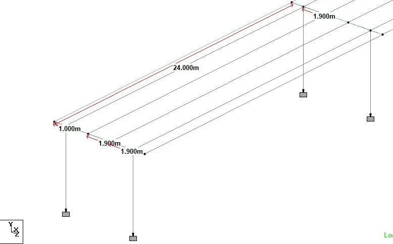
As given in the image above, centre to centre distance between girders is 1.9m.
Cantilever portion is 1m on either side as per provided cross section.
Span is 24m.
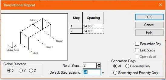
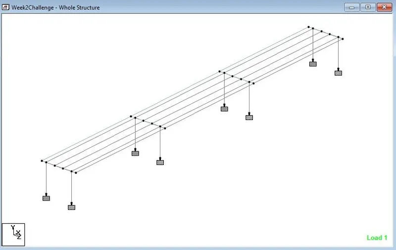
Section 1-1 shows a 3x24m structure. Accordingly, we use Gemetry>translational repeat command and taking two steps with 24m spacing in the Global X direction, gives us the total length of structure as shown below:
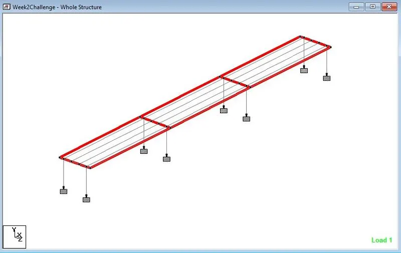
Finally, plates are provided on each span as highlighted below:
Pier height was assumed as 6m.
2. Specifications
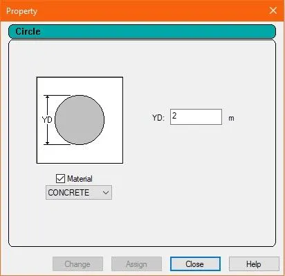
a) Pier
Diameter = 2m
b) Cross Girder:
As per given drawings, Section 1-1:
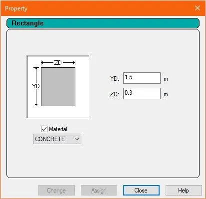
Height of Cross girder is 1.5m and thickness is 300mm.
c) Girders:
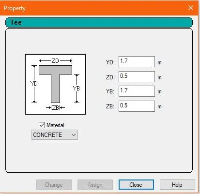
The given cross section provides height of girder as 1.9m including 200mm deck slab. If we exclude the thickness of deck slab, height of girder is 1.7m and thickness is 500mm. We provide these specifications as under.
d) Deck slab:
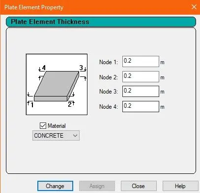
Deck slab is represented as a plate component of thickness 200mm.
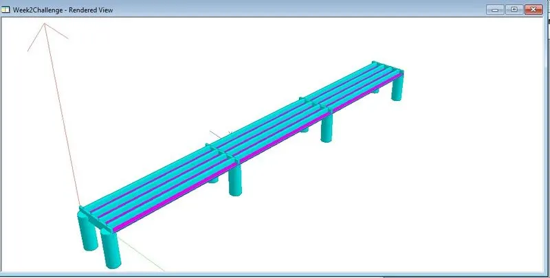
After 3D rendering we have the following structure ready for Loading.
Before moving to the loading part, we will perform various checks:
For Nodes
1. Utilities>Node tools>Orphan nodes
2. Utilities>Node tools>Duplicate nodes
If there are any Orphan nodes or Duplicate Nodes found, they shall be removed.
For Beams
1. Utilities>Beam Tools>Duplicate Beams
2. Utilities>Beam Tools>Zero Length
3. Utilities>Beam Tools>Overlapping Collinear Beams
These commands will identify duplicate beams, Zero Length Beams and Overlapping Collinear beams (if any) and shall be removed.
3. Loading
In this question we are required to analyze live loads. In bridges, live loads are in the form of vehicular loads. We will therefore take the various loads as per IRC for analysis.
For this we will go to Loading Tab > Definitions > Vehicle Definitions
The image below shows definitions for Class A loading as per IRC
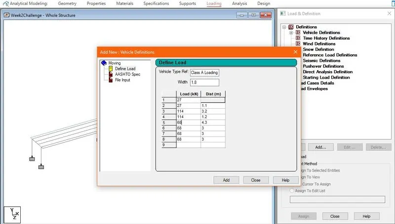
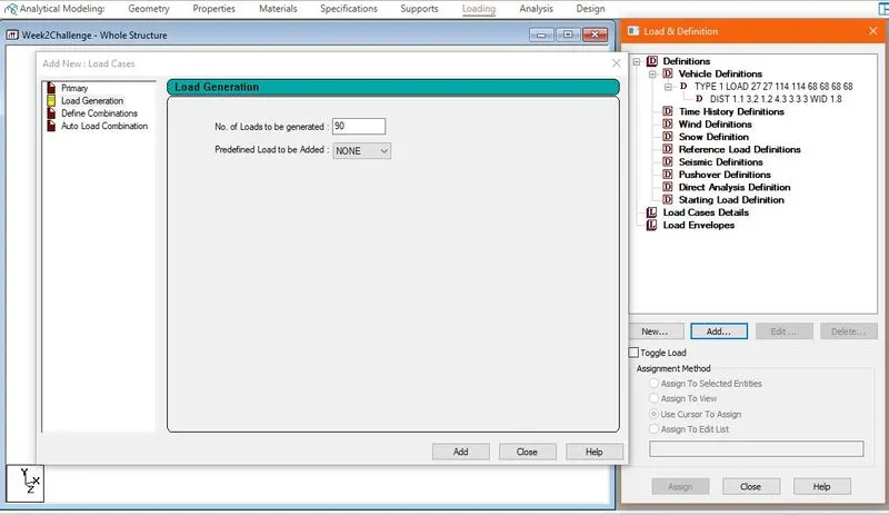
Next, we go to Load Cases Detail>Load Generation
Here, for "No. of Loads to be generated", we will take 90.
This is because total length of bridge is 3x24 = 72
Length of Vehicle of Class A is 18m
Therefore 72+18 = 90m
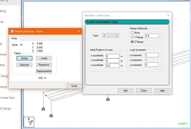
Next, we go for specifying the range of load case by clicking Add button on the created Load Case Details.
We will take the range such that it moves along global x direction with 1 unit load increment. We will also need to assign the start point which will be done by checking the co-ordinates of our starting point node. In this case, our start node is (0,0,2.9)
4. Results
We now run the file by clicking Run Analysis.
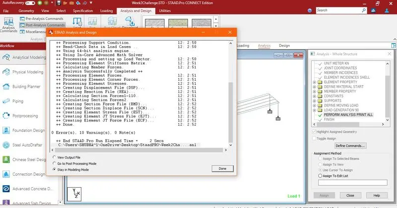
Here we have zero errors.
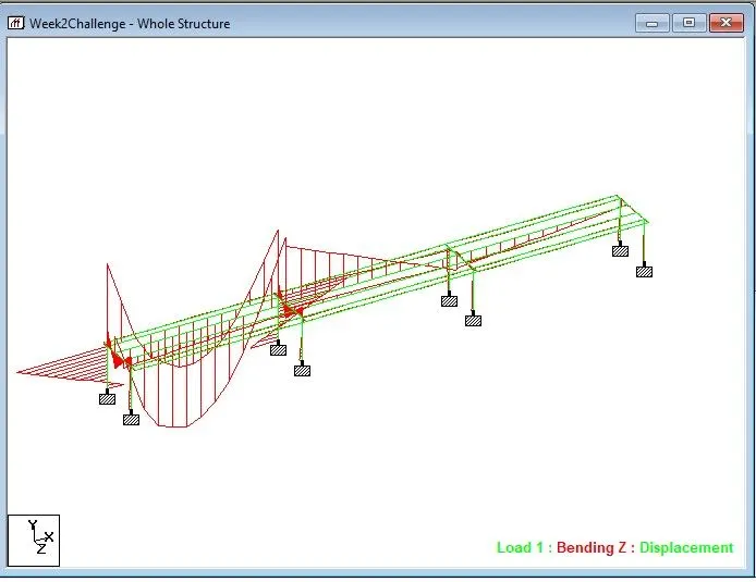
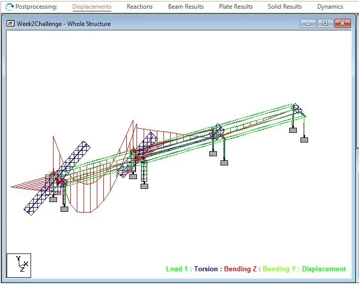
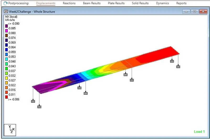
Below images show various results in the post Processing mode