Week 8 Challenge
Aim: To calculate the centrifugal force for 70RT class vehicle for a bridge of span 12.0m having 7.0m carriageway with the radius of curvature 3.0m and speed of vehicle 75.0km/hour and to apply the same and do the analysis in STAAD.Pro.
Given:
Span of the bridge = 12.0m
Width of Carriageway = 7.0m
Radius of curvature = 3.0m
Live Load = 70RT
Speed of vehicle = 75.0km/hour
Manual Calculation:
The moving of a vehicle in a curve produces an outward pushing force from the bridge which exerts loads on the structural elements of the bridge called as the centrifugal loads.
C = WV^2/127R
where,
C = Centrifugal force acting normal to traffic at the point of action of wheel or uniformly distributed over every length on which a udl acts in tonnes
W = Live load in case of wheel loads, each load being considered as acting over the ground conact length specified un clause 204 in tonnes or Live load in case of uniformly distributed Live load in tonne/m linear
V = Design speed of vehicle using bridge in km/hr
R = Radius of curvature in m
Therefore, C = (70*75*75)/(127*3) = 1033.4645kN
This has to be applied in STAAD.Pro
Procedure in STAAD.Pro:
1. Bridge Deck of 12.0m span has been modelled in STAAD.Pro.
2. Five Cross beams with 3.0m spacing are drawn and Nine Main girders are drawn as per the drawing given.
3. Plates are drawn fo deck slab.
4. Simply supports are assigned to the location mentioned in the given drawing for bearings by using the option General -> Supports -> pinned supports -> add -> assign to selected nodes
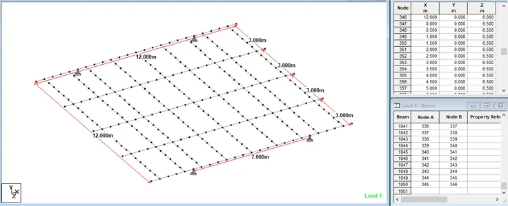
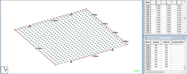
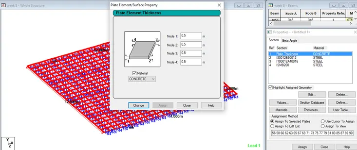
5. Plates of thickness 0.5m is assigned to deck slab using the option
General -> Properties-> thickness -> 0.5 -> material : concrete -> add -> assign to selected plates
6. Properties are assigned for main girders specified in the drawing given using the option
General -> Properties -> section data base -> Indian-> I80012B50012-> material : steel -> add-> assign to selected beam (Main girders)
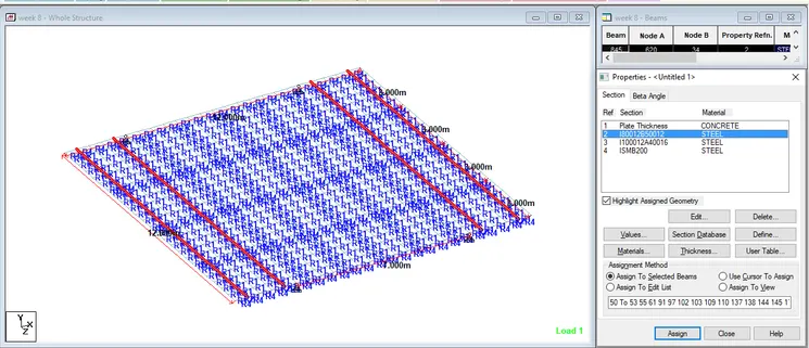
General -> Properties -> section data base -> Indian-> I100012A40016-> material : steel -> add-> assign to selected beam (Main girders)
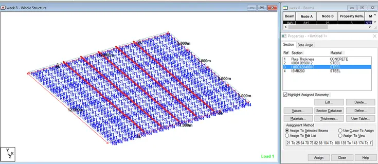
General -> Properties -> section data base -> Indian-> I100012A40016-> material : steel -> add-> assign to selected beam (Cross girders)
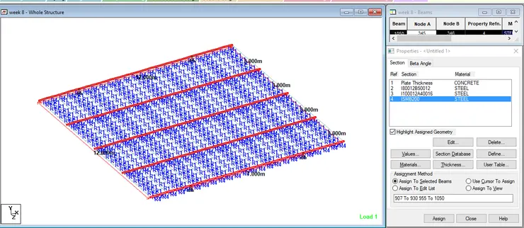
7. Centrifugal load is applied using the option -> General -> Definition-> vehivle definition
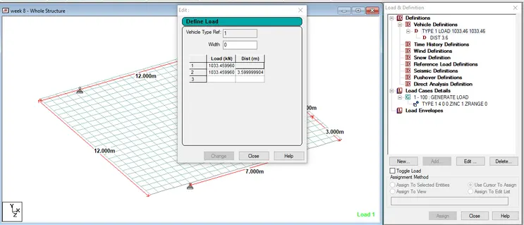
General -> Load case details-> add -> Load generation-> 100 -> add
Load generation -> enter the values of x, y & z coordinates-> add
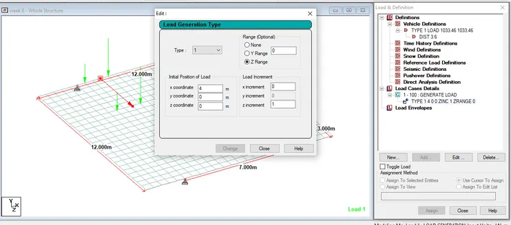
8. After assigning materials, section properties, load, Analysis is done by using the option
Commands -> Analysis -> Perform analysis
Analyze -> Run Analysis
9. To Bending moment diagram for longitudinal girders, go to post processing -> Beams -> Forces -> Mz in Mton-m
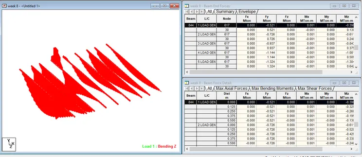
Maximum value of bending moment in Longitudinal girder is obtained by selecting all the longitudinal girders, click Report-> Section forces-> Moment Mz -> sort : Low to high (sagging moment) -> Ok
BMmax = -83.642 Mton-m, for beam no. = 384 for load combination = 6
click Report-> Section forces-> Moment Mz -> sort : high to low (hogging moment) -> Ok
BMmax = 29.189 Mton-m, for beam no. = 770 for load combination = 13
To Shear force diagram, go to post processing -> Beams -> Forces -> Fy in Mton
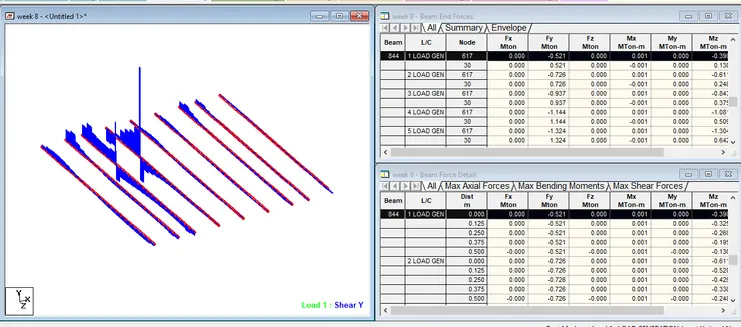
Maximum value of Shear force in Longitudinal girder is obtained by selecting all the longitudinal girders, click Report-> Section forces-> Shear Y-> Ok
SFmax = -60.119 Mton, for beam no. = 700 for load combination = 11
10. To Bending moment diagram for cross girders, go to post processing -> Beams -> Forces -> Mz in Mton-m
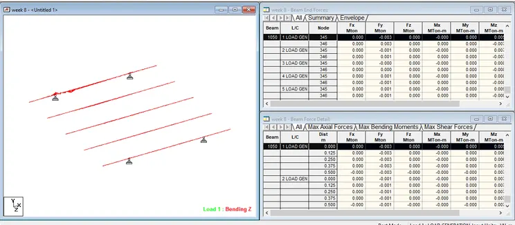
Maximum value of bending moment in Crossgirder is obtained by selecting all the cross girders, click Report-> Section forces-> Moment Mz -> sort : Low to high (sagging moment) -> Ok
BMmax = -2.363 Mton-m, for beam no. = 1017 for load combination = 1
click Report-> Section forces-> Moment Mz -> sort : high to low (hogging moment) -> Ok
BMmax = 2.331 Mton-m, for beam no. = 1004 for load combination = 1
To Shear force diagram, go to post processing -> Beams -> Forces -> Fy in Mton
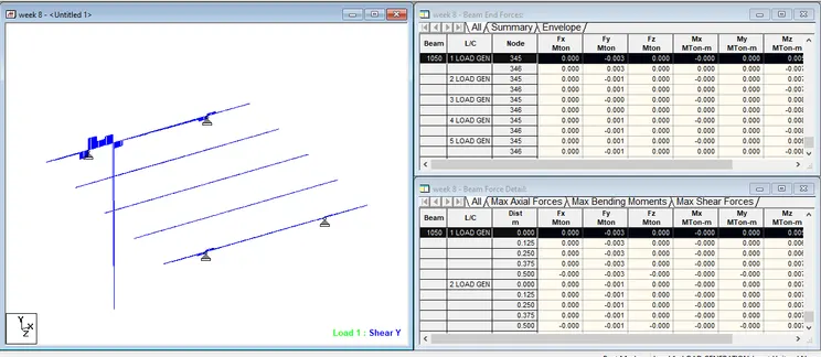
Maximum value of Shear force in cross girder is obtained by selecting all the cross girders, click Report-> Section forces-> Shear Y-> Ok
SFmax = -104 Mton, for beam no. = 1034 for load combination = 7
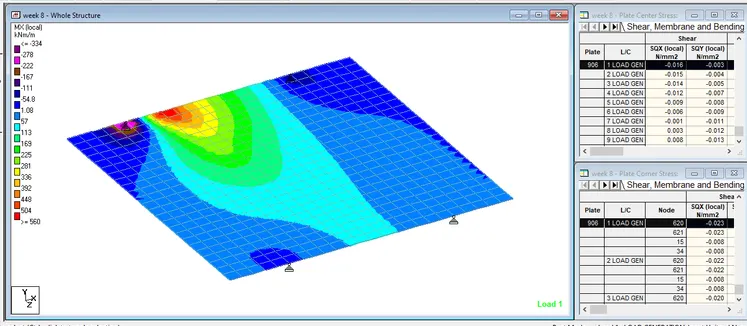
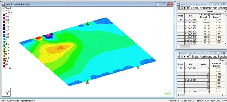
11. BEnding MX and MY in plates (deck slab) are obtained from post processing -> plates -> contour

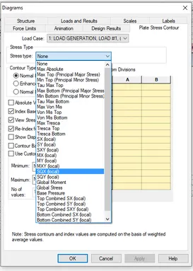
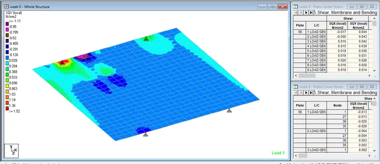
Shear SQX and SQY in plates (deck slab) are obtained from post processing -> plates -> contour