Project 1
Aim: To calculate the dead load, IRS live loads, Earth pressure load, wind load and seismic loads for the bridge structure at Ahmedabad Metro rail project and applying the loads in STAAD.Pro.
Introduction:
1. IRS Live Loads
In Week 3, we are introduced to IRS, that is, Indian Railway Standards. The lessons taught in this Week were:
- Introduction to Indian Railway Standards (IRS) Code.
- IRS Gauge Calculation.
- Broad Gauge Loading.
- Metre Gauge Loading.
- Metro Rail Loading.
Discussion:
- Introduction to Indian Railway Standards (IRS) Code
- Indian Railway Standards or briefly the IRS Code were developed by Indian Railways for the purpose of designing and construction of Railway related structures.
- The various IRS loads for design of bridges includes
- Metro Rail Loading
- Broad gauge Loading
- Electric Train
- Gauge A and Gauge B Loading
Metro Rail Loading
- Axle Loading = 17 tons
- Maximum No. of cars = 6 nos.
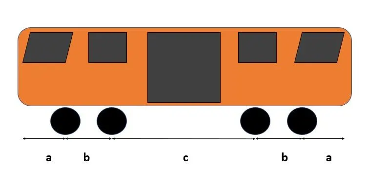
- Wheel Configuration
- Lengh a = 2150mm
- Length b = 2200mm
- Length c = 12400mm
- Length of the car = 21100mm
Broad Gauge Loading
- Here there is no symmetry in loading and distance between wheels also differs.
- The Maximum Axle loading is in the middle wheel portion which is around 19.25 tonnes and Minimum Axle Loading is in the front wheel which is 11.84 Tonnes.
- There is one small wheel followed by four big wheels and then 5 small wheels of differing sizes, distances and axle loading.
- Unlike Metro Loading, Broad Gauge Loading is more complicated.
Electric Train Loading
- Electric Train Loading is nothing but Metre Gauge Loading.
- It has been used for several decades.
- In most cities this has been upgraded to Broad Gauge Loading.
- This is to accomodate more population.
- Each carriage has has six wheels in two sets. One set in front and the other set in the back.
- Distance between two sets is 2743mm while distcance between individual wheels is 914mm
- All three wheels in each set have same Axle Loading of 74.5kN.
- Overall Train Load is 27.8kN if we consider it as UDL.
Gauge A and Gauge B Loading
- Similar to Class A and Class B Loading in IRC, we have Gauge A and gauge B Loading in IRS.
- The maximum axle loading in Gauge A loading is 79.4. kN and minimum axle loading is 58.8 kN.
- Gauge A and Gauge B is also called 762mm Gauge.
- Unlike IRC, IRS has tables for calculation of Shear Force and Bending Moment for different spans between piers.
- Gauge B axle loading is same for all six wheels which is 59.8 kN.
2. Earth Pressure Loads
Unit Weight of Soil
- Unit Weight of Soil is defined as the total weight of soil mass W per unit of total volme V.
γ = W/V - Dry Unit Weight: It is defined as the weight of dry soil Ws per unit Vome V.
γd = Ws/V - Saturated Unit Weight: It is the ratio of Weight of fully saturated soil Wsat to its total volume V.
γsat = Wsat/V - Submerged unit weight: It is equal to saturated unit weight minus unit weight of water.
γ = γsat - γw
Soil Report and Borehole Drawing
- Soil Report: It is the report which contains detailed infromation about the soil layers present in the site and the various test results showing the shear strength c and ϕ parameters, N values and ground water table level.
- It provides the Safe Bearing Capacity values based on the test conducted on soil samples.
- Borehole diagram is provided in the soil report.
- Borehole Diagram: It is the diagram which shows the type of soil layers variations with propoerties below ground level till the termination level of borehole.
- It indicates the ground water table level and RL of starting and ending of different types of soil present below ground level.
Earth Pressure
- Earth Pressure: It is the horizontal thrust exerted by the retained earth on a vertical structural element like wall, pier, abutment, etc.
- Three conditions exist as follows:
- Earth Pressure at rest
- Active Earth Pressure
- Passive Earth Pressure
Earth Pressure at rest:
- When the vertical structural member is rigid and unyielding, the soil mass is in a state of rest and there will be no deformations and displacement.
- The Earth pressure corresponding to this state is Earth Pressure at rest.
Active Earth Pressure:
- When the vertical structural member moves away from the backfill, the soil mass expands and there is a decrease in pressure.
- The Earth pressure corresponding to this is state is called as Active Earth Pressure.
Passive Earth Pressure:
- When the vertical structural member moves towards the backfill, the soil mass is compressed and the shear resistance developed towards the vertical member and there is increase in pressure.
- The Earth pressure corresponding to this state is called as Passive Earth Pressure.
3. Wind Load
A. Wind Loads
- The Bridge strcutures are subjected to wind lods if they are located in open terrain or near coastal zone or over a river where there will be seasonal monsoon winds and cyclones.
- Wind loads are calculated as per IS: 875: Part III-2015.
- IS: 875: Part III-2015 provides the basic wind speed map of India.
- The factors k1, k2, k3, k4 are determined from code and design wind speed is calculated.
B. Wind Zones of India
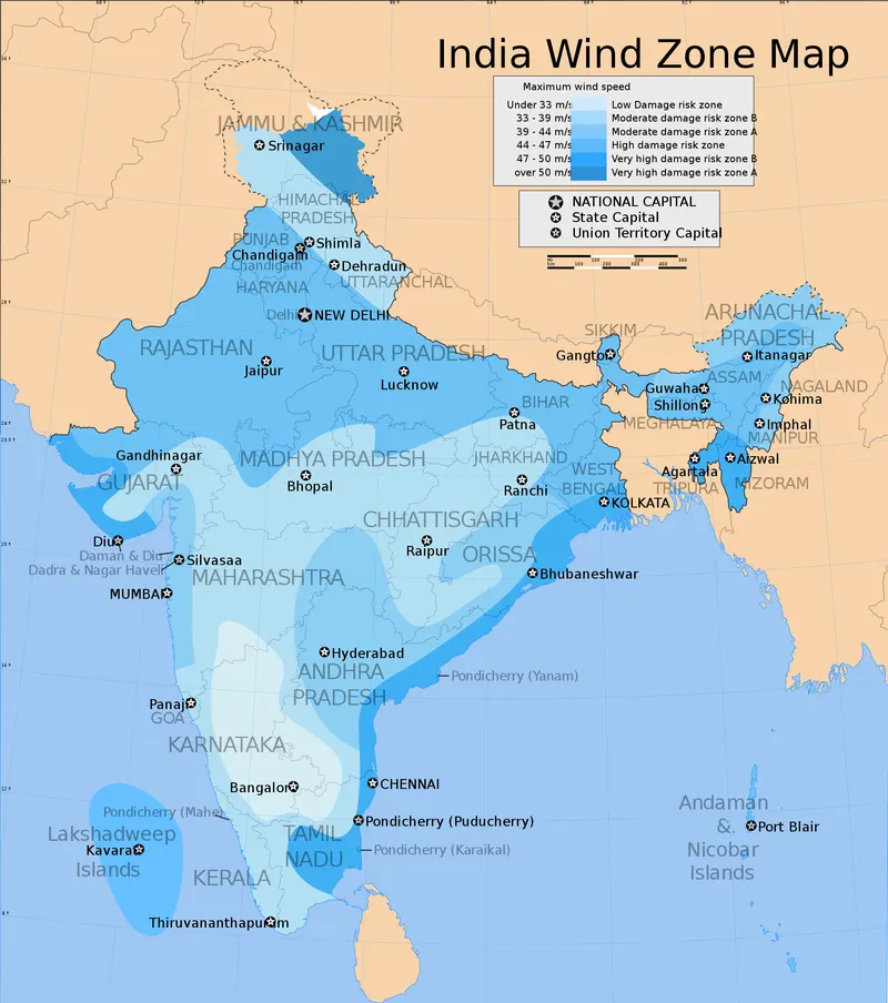
The image below shows the various wind speeds of India:
Picture Credits: Wikimedia Commons

Based on the above image, it is clear that coastal areas experince high wind speeds and therefore Wind Loads must be taken into account during designing of structures.
Ahmedabad is in the Moderate to High Risk Zone.
Calculation of Wind Load:
Design Wind Speed Vz = Vb x k1 x k2 x k3 x k4
k1 = Probabilty Factor
k2 = Height Factor
k3 = Topography Factor
k4 = Importance Factor
k1: Probabilty Factor
In determining k1, we will follow Table 1, clause 6.3.1 of IS: 875: Part III-2015 which is as follows:
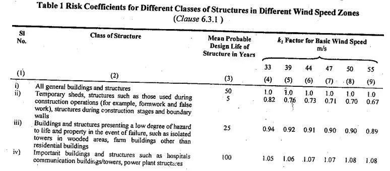
For Bridges, we will follow point (iv) i.e., "Important buildings and structures such as hospitals, communication buildings/towers, power plant structures" which have a design life of 100 years.
For Coastal regions such as Mumbai, a factor of 1.08 will be taken during wind load calculations.
k2: Terrain or Height Factor
In determining k2, we will follow Table 2, clause 6.3.2.2 of IS: 875: Part III-2015 which is as follows:
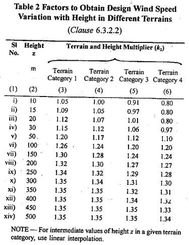
Here we have 4 categories depending on height and terrain.
As per clause 6.3.2, Terrain, Height Factor (k2 Factor)
Category 1: Exposed open terrain with few or no obstructions in which the average height of any object ssurrounding the structure is less than 1.5m. The equivalent aerodynamic roughness height, (z0.1) for this terrain is 0.002m. Typically this category represents open sea-coasts and flat plains without trees.
Category 2: Open terrain with well scattered obstrcutions having heights generally between 1.5m and 10m. The equivalent aerodynamic roughness height, (z0.2) for this terrain is 0.002m. This is the criterion for measurement of regional basic wind speeds and represents airfields, open park lands and undeveloped sparsely built-up outskirts of towns and suburbs. Open land adjacent to sea coasts may also be classified as Category 2 due to roughness of large sea waves at high winds.
Category 3: Terrain with numerous closely spaced obstructions having size of buildings/structures upto 10m in height with or without a few isolated tall structures. The equivalent aerodynamic roughness height, (z0.3) for this terrain is 0.2m. This category represents well wooded areas, and shrubs, towns and industrial areas full or partially developed. It is likely that the, next higher category than this will not exist in design sitautions.
Category 4: Terrain with numerous large high closely spaced obstrcutions. The equivalent aerodynamic roughness height, (z0.4) for this terrain is 2.0m. This category represents large city centres, generally with obstructions above 25m and well developed industrial complexes.
k3: Topography Factor
As per clause 6.3.3 of IS 875:
The basic wind speed Vb takes into account the general level of site above sea level. This does not allow for local topographic features such as hills, valleys, cliffs, escarpments, or ridges which can significantly affect wind speed in their vicinity. The effect of topography is to accelerate wind near the summits of hills or crests of cliffs, escarpments or ridges and decelerate the wind in valleys or near foor of cliffs, steep escarpments, or ridges.
The effect of topography shall be significant at a site when the upwind slope (θ) is more than about 3 degrees, and below that, the value of k3 may be taken to be equal to 1.0. The value of k3 is confined in the range of 1.0 to 1.36 for slopes more than 3 degrees. It may be noted that the value of k3 varies with height above ground level, at a maximum near ground, and reducing to 1.0 at higher levels.
k4: Importance Factor for Cyclonic Region
As per clause 6.3.4 of IS 875, k4 may be taken as follows:
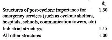
East and West coastal areas are most susceptible to cyclonic factors.
In order have safe structures, structures built within 60 km of the seashore, we will take into consideration k4 for wind analysis.
For bridges we will take 1.15 as the value of k4.
Wind Pressure
The wind pressure at any height above mean ground level shall be obtained by the following relationship between wind pressure and wind speed:
Pz = 0.6Vz^2
Where
Pz = Wind pressure at height z, in N/sqm
Vz = Design wind speed at height z in m/s
The design wind speed pressure Pd can be obtained as,
Pd = Kd.Ka.Kc.Pz
Where,
Kd = Wind directionality factor (1.0 for sircular, semi circular and 0.9 for rectangular, square etc)
Ka = Area averaging factor (Actual area exposed to wind)
Kc = Combination factor (0.9 is considered as per IS 875 which is recommended value)
We will now use these equations for the calculation of Wind Load on our structure.
4. Seismic Load
IS: 1893 Code
- IS 1893 provides us the seismic zone map of India with Zone II to Zone IV.
- Seismic loads are calculated in accordance with IS 1893 code.
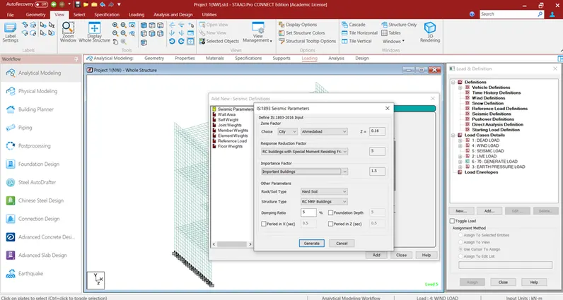
- Zone factor, importance factor, response reduction factor are the factors taken from IS 1893 code.
Seismic Zones of India
- Seismic zones are four starting with Zone II and then Zone III, Zone IV and Zone V.
- The Zone factor varies between 0.10 to 0.36 based on seismic zones.
Procedure:
Given data
STAAD model is given
Unit weight of soil = 18 kN/m3
Location of the bridge = Ahmedabad
Wind load calculation is done as per IS875
Seismic load calculation is done as per IS 1893
Modelling
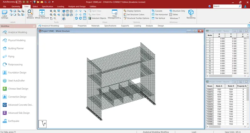
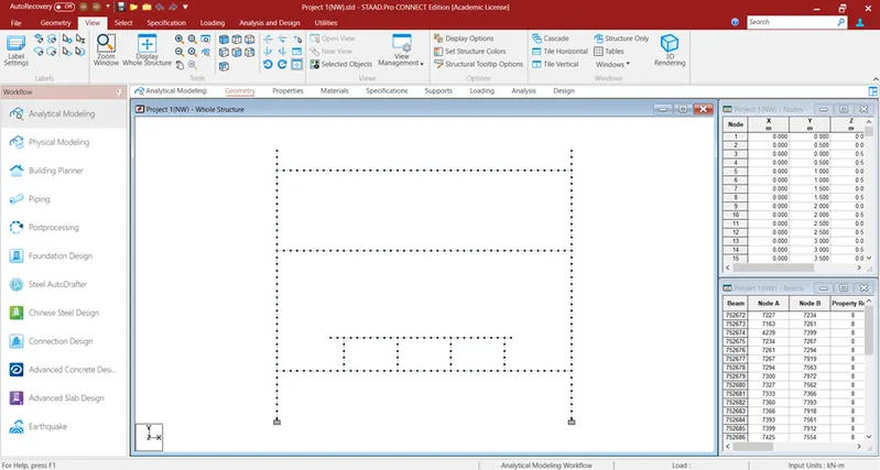
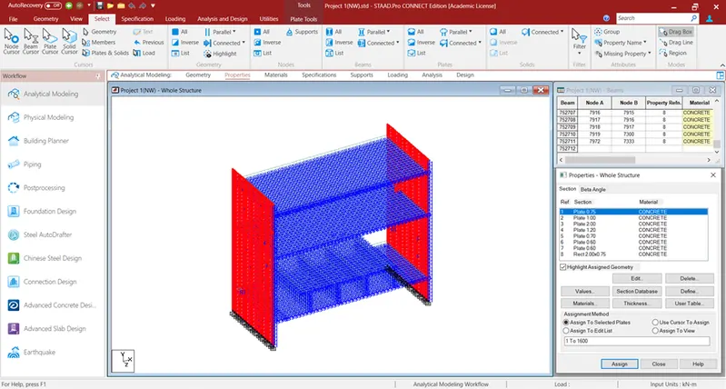
The model is given & the structure is modelled using plate & beam elements. The thickness of the plates is defined in the model.
Properties
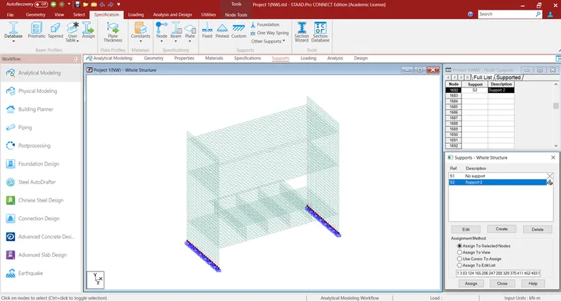
Supports
Load calculation & application on the structure
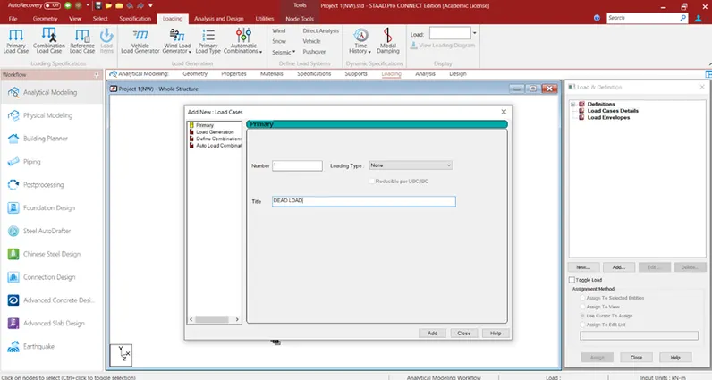
- Dead load
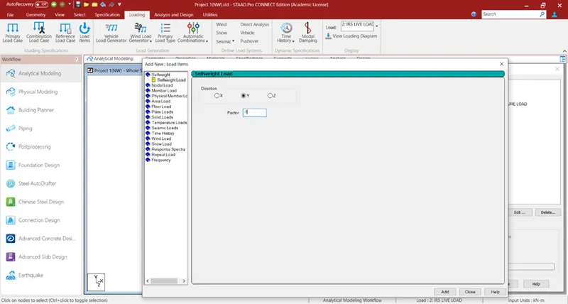
The dead load carried by a girder or member shall consist of the portion of the weight of the superstructure which is supported wholly or in part by the girder or member including its own weight. The unit weights of materials shall be used in determining loads. The loads are applied using self-weight command in STAAD.
- IRS live load
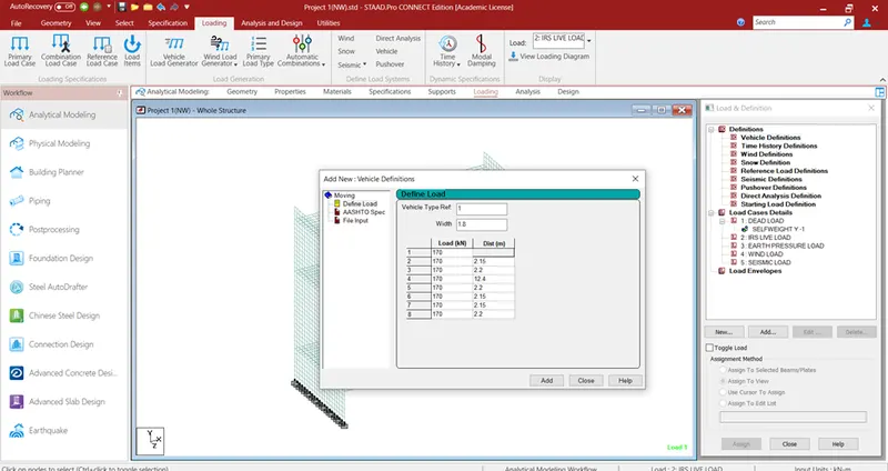
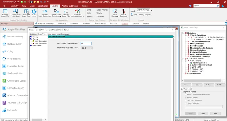
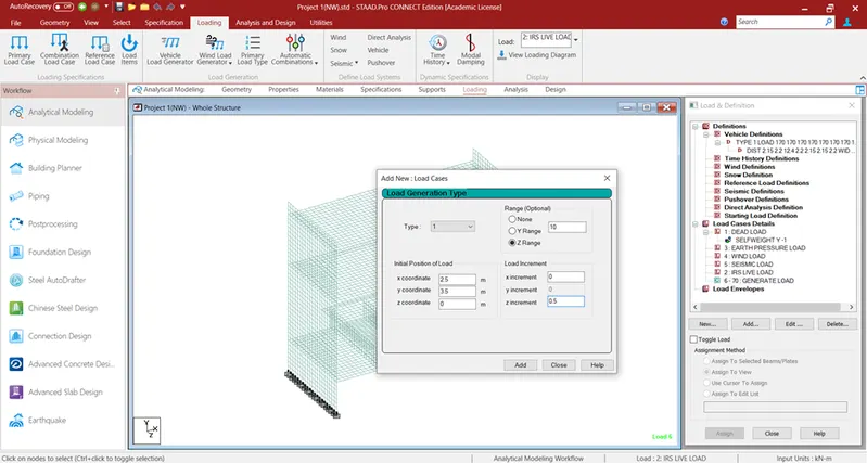
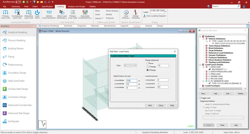
The loads are defined using Vehicle definitions. The width & type of vehicle is specified along with the intensity of the vehicle load. The IRS loads are applied as below. No. of load generations are calculated based on the span of the structure. The vehicle is placed on the structure accordingly.
- Earth pressure load
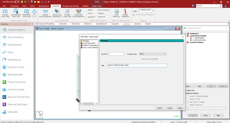
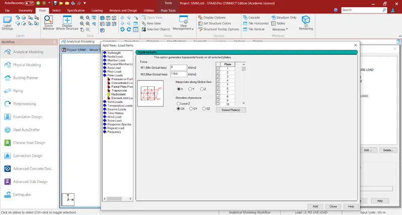
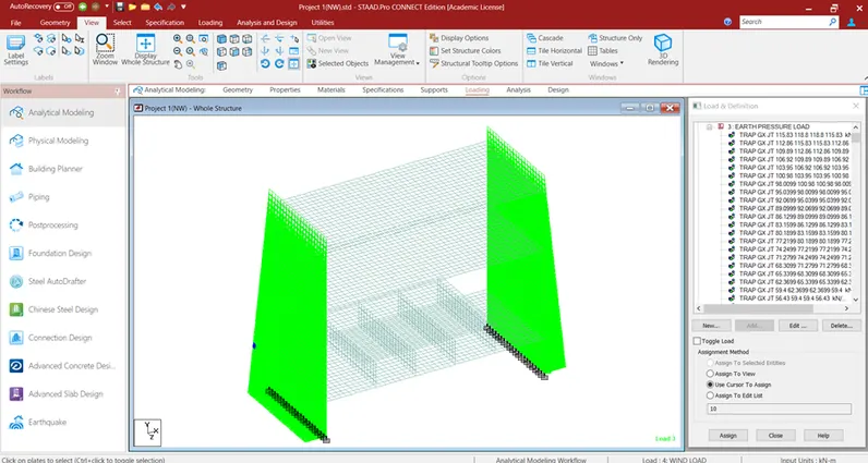
The structures designed to retain earth fills shall be proportioned to withstand the calculated pressure. Load due to earth pressure acting on the structure = ka.γ.h = 0.33 x 18 x 20 = 118.8 kN/m
The earth pressure is applied in the model as follows:
- Wind load
The wind pressure acting on a bridge depends on the geographical locations, the terrain of surrounding area, the fetch of terrain upwind of the site location, the local topography, the height of bridge above the ground, horizontal dimensions and cross-section of bridge or its element under consideration. The maximum pressure is due to gusts that cause local and transient fluctuations about the mean wind pressure.
Basic wind speed in Ahmedabad, Vb = 39 m/s
k1 = probability factor = 1.06 (Table 1)
k2 = terrain roughness & height factor = 0.8 (Table 2)
k3 = topography factor = 1.0
k4 = importance factor = 1.0
Design Wind speed, Vz = Vb k1 k2 k3 k4
= 39 x 1.06 x 0.8 x 1.0 x 1.0
= 33.072 m/s
Design Wind pressure, pz = 0.6 Vz2
= 0.6 x 33.072
= 0.656 kN/m2
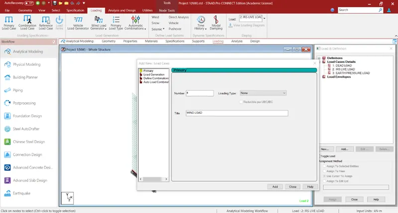
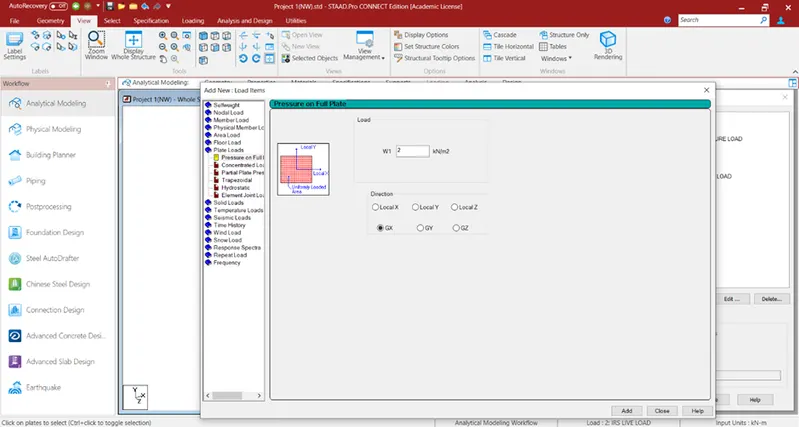
Wind load is considered as 2 kN/m2 conservatively.
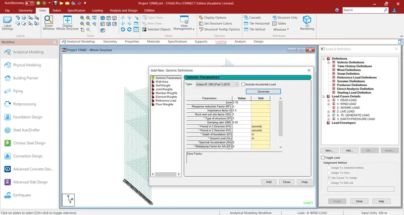
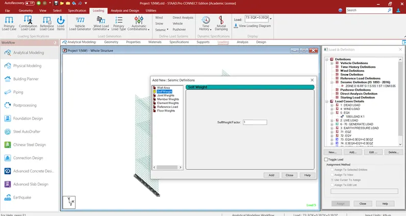
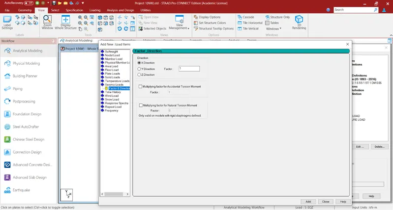
- Seismic load
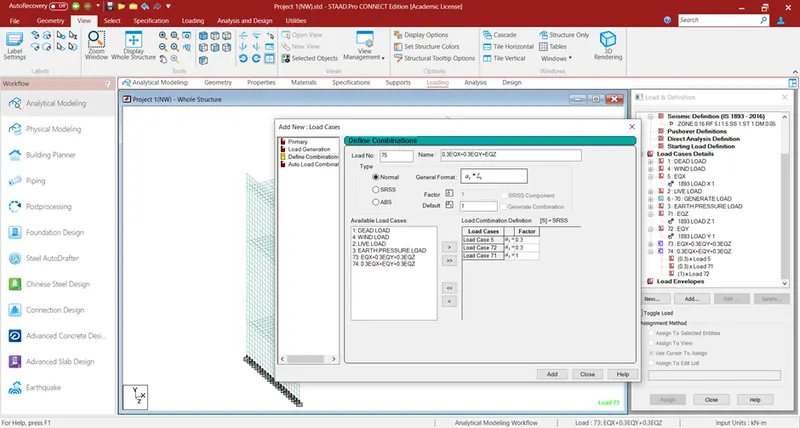
Seismic load definition & application is carried out as below. Combinations are also defined.
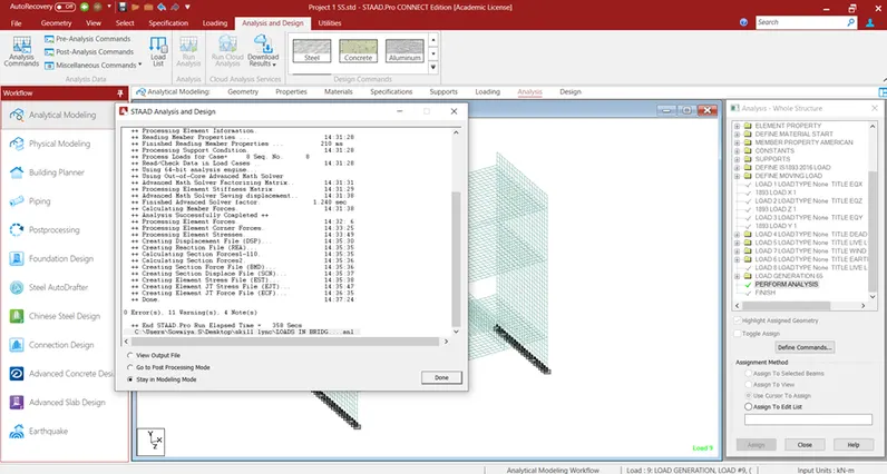
Analysis
Results
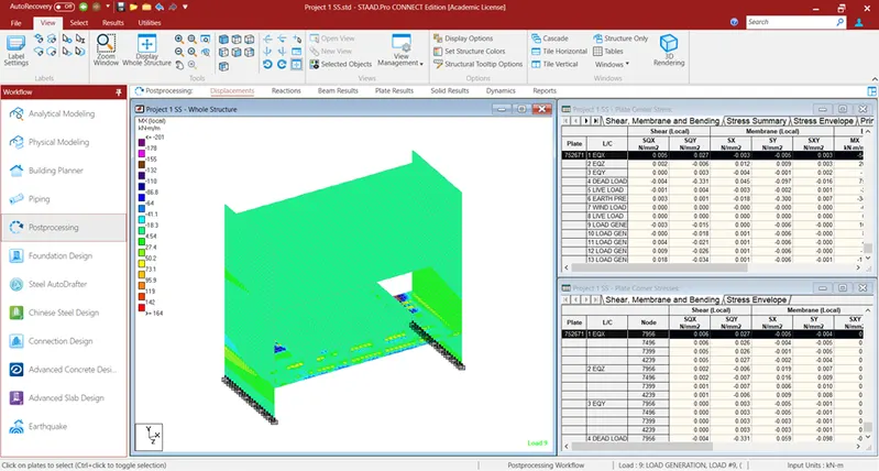
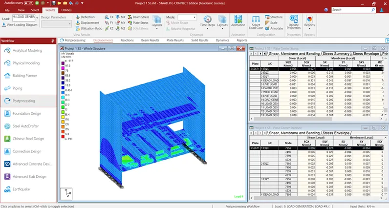
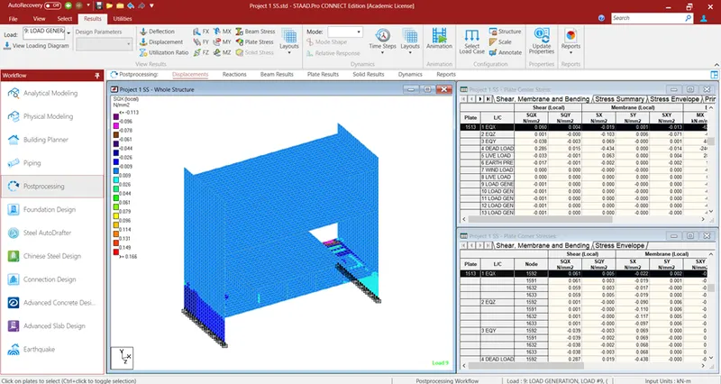
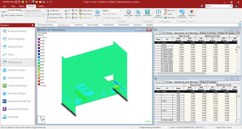
After analysis, the plate results are determined & are given below.