Week 2 Challenge
1. Aim: To Define all loads to be applied in the abutment of the bridge as per IRC 6 and mention the clauses. Check for overturning and sliding of 4 m height of Abutment (from ground level), embedded 2 m in ground.
Theory: A bridge abutment is a structure which connects the deck of a bridge to the ground, at the ends of a bridge span, helping support its weight both horizontally and vertically. It resists the lateral movement from the earth fill of the bridge approach.
Explanation:
Different kinds of loads acting on the Abutment are:
- Dead load/Self weight – It is the weight of the structural components like deck slab, girders, Pier/abutment cap, pier shaft/abutment stem (excluding crash barrier, wearing coat, Light pole) in a structure. It acts in vertically downward direction. Mentioned in Clause 203 of IRC: 06-2017.
- Super imposed dead load - It is the weight of Crash barrier, wearing coat, Light pole over the deck of the superstructure. It acts in vertically downward direction. Mentioned in Clause 206 of IRC: 06-2017.
- Earth pressure – It is the weight of soil resisted by the pier shaft or abutment stem. It acts in horizontal direction. Mentioned in Clause 214 of IRC: 06-2017.
- Live load – It is the load of the traffic above the deck due to movement of vehicles. It acts in vertically downward direction. Mentioned in Clause 204 of IRC: 06-2017.
- Braking load - It is a load induced when brakes are applied in a vehicle. It acts in horizontal direction. Mentioned in Clause 211 of IRC: 06-2017.
- Temperature load – This load is considered due to fluctuation in temperature of the location where the bridge is built. It acts in horizontal direction. Mentioned in Clause 215 of IRC: 06-2017.
- Wind load – It is a load exerted by the wind at that particular location where the bridge is built in horizontal direction & vertical direction. Force in vertical direction tends to lift the structure and force in horizontal direction tends to push the structure. Mentioned in Clause 209 of IRC: 06-2017.
- Seismic load – A force due to earthquake acting in horizontal directions and vertical direction. Force in vertical direction tends to lift the structure and force in horizontal direction tends to push the structure.
- Water pressure – It is a force exerted by the water in a stream/river to pier shaft/ Abutment stem in lateral direction. Mentioned in Clause 210 of IRC: 06-2017.
Check for overturning and sliding:
Input Data:
Dimensions
- Top width of the retaining wall = 300mm
- Bottom width of Retaining wall = 450mm
- Size of foundation = 1000 x 2950 x 600 mm
- Width of toe = 1000mm
- Width of heel = 1500mm
- Length of Retaining wall = 1m
Concrete & Steel Data
- Grade of Concrete = M30
- Grade of Steel = Fe500
- Unit Weight of Concrete = 25kN/m3
Soil Data
- Unit Weight of Soil = 20kN/m3
- Angle of internal friction of Soil = 30 deg
- Surcharge angle = 0 deg
- Angle of inclination of wall from vertical face = 90 deg
- Angle of friction between wall & soil = 20 deg
- Safe Bearing Capacity of Soil = 200kN/m3
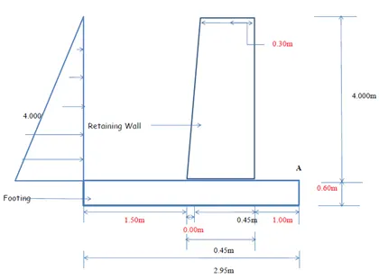
Load Calculations
|
Description |
Shape |
L |
B |
D |
Lever arm |
Vertical load |
Horizontal load |
Vertical moment |
Horizontal moment |
|
Footing |
Rec |
1 |
2.95 |
0.6 |
1.475 |
44.25 |
- |
65.27 |
- |
|
Wall |
Rec |
1 |
0.45 |
4.0 |
1.225 |
45.00 |
- |
55.13 |
- |
|
Tri |
1 |
0.00 |
4.0 |
1.45 |
0.00 |
- |
0.00 |
- |
|
|
Wt of soil |
Rec |
1 |
1.5 |
4.0 |
2.2 |
120.00 |
- |
264.00 |
- |
|
Tri |
1 |
0.0 |
4.0 |
1.45 |
0.00 |
- |
0.00 |
- |
|
|
Active EP |
Tri |
1 |
- |
4.0 |
1.68 |
- |
53.37 |
- |
89.7 |
|
Tri |
1 |
- |
1.4 |
0.59 |
- |
6.54 |
- |
3.8 |
|
|
Total |
209.25 |
46.83 |
384.39 |
85.81 |
Factor of safety against sliding = 0.5*W/H = 0.5*209.25/46.83 = 2.23 >1.5 Hence OK
Factor of safety against overturning = Mr/Mo = 384.39/85.82 = 4.48>2 Hence OK
2. Aim: To decide the boreholes location and its depth of exploration in case of shallow foundation and the parameters to get from the site/geotechnical investigations for design of the foundation. To List different type of soils/rock (minimum 5) and the criteria to be followed for the shallow foundations for selecting the foundation level, their characteristics with pictures and to draw a typical borehole showing all the data.
Theory and Explanation:
- Soil investigation is required for the following purposes – To know the allowable bearing capacity of foundation for proposed building. To know the depth and type of foundation for the proposed building. To know the allowable passive resistance for the foundation of proposed building. To know the type, grading and nature of soil. To know the ground water level.
- Subsurface exploration in shallow foundation depends on the following parameters:
- Nature of the soil and its parameters
- Selection of depth suitable for the structure
Based on the following criteria the depth of foundation is fixed.
- Based on embedment: As per IRC 78, if we don’t have any data the embedment should be minimum 2m from the ground level.
- Based on scouring strata: We have to calculate the scour level from the hydrological data. The founding level should be kept 2m below scour level.
- Based on rock strata: If we have a good rock at the top of the ground level itself then no need to go till 2m. We can place at the top as well.
- Based on SPT: Standard penetration test is designed to provide the geotechnical information of the soil. It provides a measure of penetration resistance.
- Determining bearing capacity of the soil
- Determining settlement of soil
- Location of water table
- Determining density of soil and other parameters
- Bore Hole: Bore hole is a deep vertical hole with smaller diameter drilled into the ground to obtain the soil samples for the purpose of testing the soil for geotechnical report and for the design of the foundation. Bore holes are drilled to find the bearing capacity of the soil, nature of the soil strata, liquefaction in the soil. Bore holes should be done at the proposed location of abutment and pier.
When we are collecting the samples of the soil we have to make bore log, we have to go deeper. This depth generally depends on the width of the foundation as per the loadings, bearing capacity multiplied by 1.5 (As per MORTH, IRC 78). The samples obtained are utilized to get necessary information about the soil characteristics by means of laboratory tests.
Depth of exploration = 1.5 x Width of foundation
Bore log are done in the pier location. Under every foundation we need to have one bore log to assess the soil criteria.
Results:
Results must give details of ground conditions, previous use of site, present conditions, groundwater and drainage pattern. The tests must give adequate information to determine:
- The soil’s bearing capacity
- Settlement characteristics
- Behavior during and after foundation construction
- Where necessary, its chemical make-up and condition.
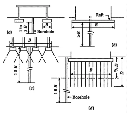
Fig: Figure showing the depth of bore hole
Credit: (http://civil-engineeringnotes.blogspot.com/2011/06/13-borehole-layout.html)
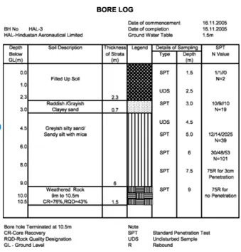
Fig: Typical bore log showing bore hole data
- Soil: In civil engineering, soil is a naturally occurring, loose/un-cemented/weakly cemented/relatively unconsolidated mineral particles, organic or inorganic in character, lying over the bed rock which is formed by weathering of rocks.