Week 5 Challenge
Aim:
To calculate the design wind loads for the bridges to be designed at Mumbai and apply the wind loads on StaadPro.
Introduction:
1. Wind Loads
- The Bridge strcutures are subjected to wind lods if they are located in open terrain or near coastal zone or over a river where there will be seasonal monsoon winds and cyclones.
- Wind loads are calculated as per IS: 875: Part III-2015.
- IS: 875: Part III-2015 provides the basic wind speed map of India.
- The factors k1, k2, k3, k4 are determined from code and design wind speed is calculated.
2. Wind Zones of India
The image below shows the various wind speeds of India:
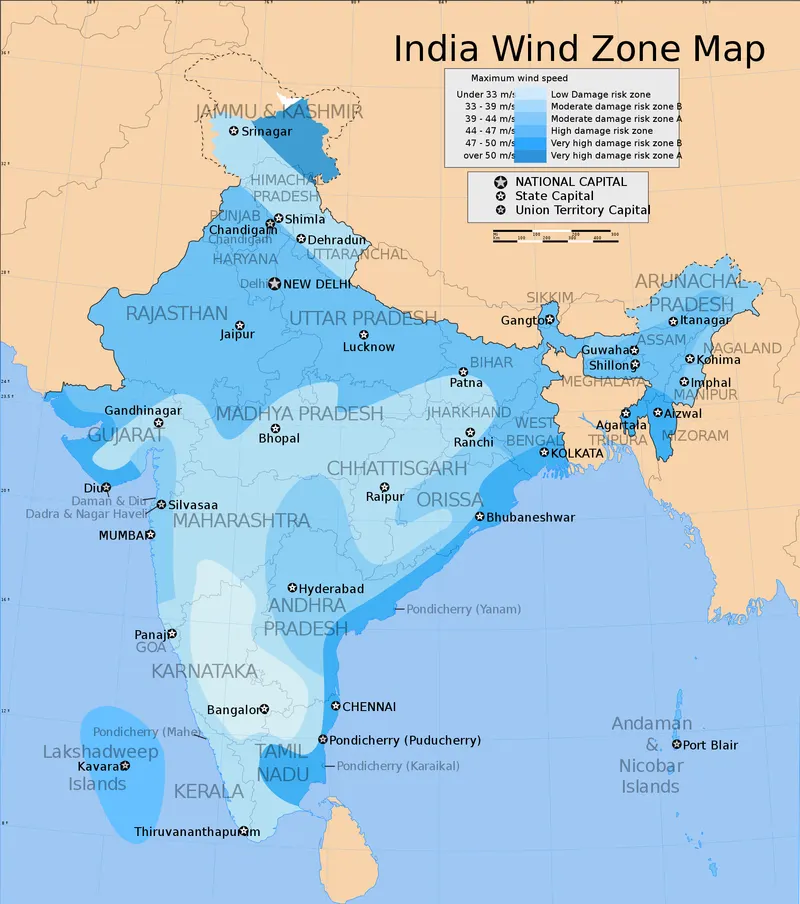
Picture Credits: Wikimedia Commons

Based on the above image, it is clear that coastal areas experince high wind speeds and therefore Wind Loads must be taken into account during designing of structures.
Mumbai is in the Moderate to High Risk Zone.
3. Calculation of Wind Load
Design Wind Speed Vz = Vb x k1 x k2 x k3 x k4
k1 = Probabilty Factor
k2 = Height Factor
k3 = Topography Factor
k4 = Importance Factor
k1: Probabilty Factor
In determining k1, we will follow Table 1, clause 6.3.1 of IS: 875: Part III-2015 which is as follows:
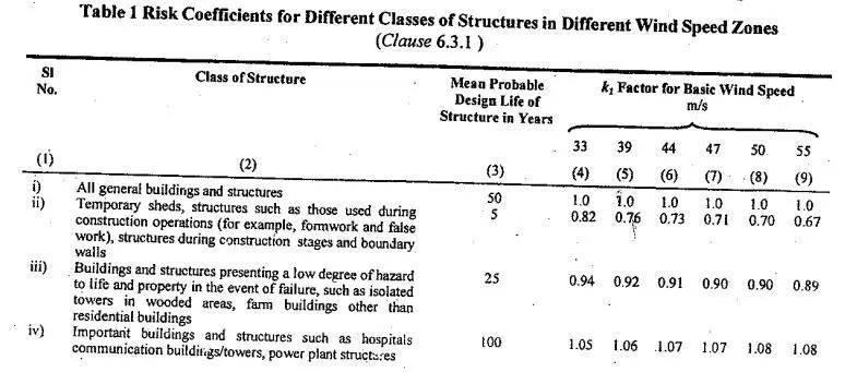
For Bridges, we will follow point (iv) i.e., "Important buildings and structures such as hospitals, communication buildings/towers, power plant structures" which have a design life of 100 years.
For Coastal regions such as Mumbai, a factor of 1.08 will be taken during wind load calculations.
k2: Terrain or Height Factor
In determining k2, we will follow Table 2, clause 6.3.2.2 of IS: 875: Part III-2015 which is as follows:
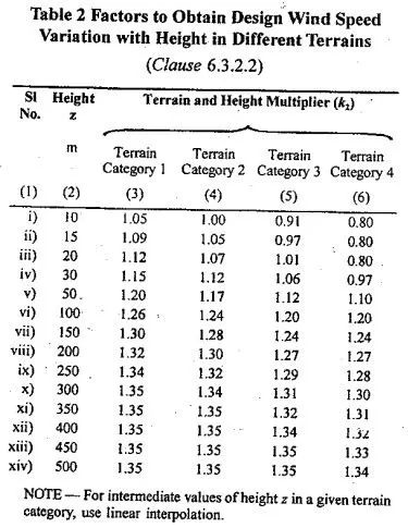
Here we have 4 categories depending on height and terrain.
As per clause 6.3.2, Terrain, Height Factor (k2 Factor)
Category 1: Exposed open terrain with few or no obstructions in which the average height of any object ssurrounding the structure is less than 1.5m. The equivalent aerodynamic roughness height, (z0.1) for this terrain is 0.002m. Typically this category represents open sea-coasts and flat plains without trees.
Category 2: Open terrain with well scattered obstrcutions having heights generally between 1.5m and 10m. The equivalent aerodynamic roughness height, (z0.2) for this terrain is 0.002m. This is the criterion for measurement of regional basic wind speeds and represents airfields, open park lands and undeveloped sparsely built-up outskirts of towns and suburbs. Open land adjacent to sea coasts may also be classified as Category 2 due to roughness of large sea waves at high winds.
Category 3: Terrain with numerous closely spaced obstructions having size of buildings/structures upto 10m in height with or without a few isolated tall structures. The equivalent aerodynamic roughness height, (z0.3) for this terrain is 0.2m. This category represents well wooded areas, and shrubs, towns and industrial areas full or partially developed. It is likely that the, next higher category than this will not exist in design sitautions.
Category 4: Terrain with numerous large high closely spaced obstrcutions. The equivalent aerodynamic roughness height, (z0.4) for this terrain is 2.0m. This category represents large city centres, generally with obstructions above 25m and well developed industrial complexes.
k3: Topography Factor
As per clause 6.3.3 of IS 875:
The basic wind speed Vb takes into account the general level of site above sea level. This does not allow for local topographic features such as hills, valleys, cliffs, escarpments, or ridges which can significantly affect wind speed in their vicinity. The effect of topography is to accelerate wind near the summits of hills or crests of cliffs, escarpments or ridges and decelerate the wind in valleys or near foor of cliffs, steep escarpments, or ridges.
The effect of topography shall be significant at a site when the upwind slope (θ) is more than about 3 degrees, and below that, the value of k3 may be taken to be equal to 1.0. The value of k3 is confined in the range of 1.0 to 1.36 for slopes more than 3 degrees. It may be noted that the value of k3 varies with height above ground level, at a maximum near ground, and reducing to 1.0 at higher levels.
k4: Importance Factor for Cyclonic Region
As per clause 6.3.4 of IS 875, k4 may be taken as follows:
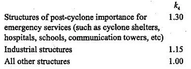
East and West coastal areas are most susceptible to cyclonic factors.
In order have safe structures, structures built within 60 km of the seashore, we will take into consideration k4 for wind analysis.
For bridges we will take 1.15 as the value of k4.
Wind Pressure
The wind pressure at any height above mean ground level shall be obtained by the following relationship between wind pressure and wind speed:
Pz = 0.6Vz^2
Where
Pz = Wind pressure at height z, in N/sqm
Vz = Design wind speed at height z in m/s
The design wind speed pressure Pd can be obtained as,
Pd = Kd.Ka.Kc.Pz
Where,
Kd = Wind directionality factor (1.0 for sircular, semi circular and 0.9 for rectangular, square etc)
Ka = Area averaging factor (Actual area exposed to wind)
Kc = Combination factor (0.9 is considered as per IS 875 which is recommended value)
We will now use these equations for the calculation of Wind Load on our structure.
Procedure:
1. Given
- The height of the bridge above ground level is 9 m.
- It is located in open terrain with well scattered obstructions of height less than 10m.
- The pier size is 1.5 x 1.5 m.
We will calculate the design wind loads for bridges to be designed at Mumbai.
- The height of the bridge above ground level is 9m.
- It is located in open terrain with well scattered obstructions of height less than 10m.
- The pier size is 1.5 x 1.5m
2. Manual Calulations
The Wind Speed Vz = Vb x k1 x k2 x k3 x k4
- Basic Wind Speed is taken from the Wind Zone Map so Vb = 47 m/s.
- Factor k1
Refering Table 1 of IS:875: part III-2015
For important strcuture and 47 m/s, k1 = 1.07 - Factor k2
Refering Table 2 of IS:875: part III-2015
For height of 9m category 2 structure, k2 = 1.00 - Factor k3
As per clause 6.3.3 of IS:875: part III-2015 for upwind slope less than 3 dgrees, k3 = 1.00 - Factor k4
When the location is within 60 km of the ocean, the cyclonic factor is taken in to account k4 = 1.300
Design Wind Speed Vz = Vb x k1 x k2 x k3 x k4
Vz = 47 x 1.07 x 1.00 x 1.00 x 1.300
Vz = 65.38 m/s
Wind Pressure Pz = 0.6 x Vz^2
Pz = 0.6 x 65.38 x 65.38
Pz = 2565 N/sqm
Pz = 2.57 kN/sqm
We will now apply these obtained values in our StaadPro Analysis.
3. Wind Load Analysis in StaadPro
Step 1: Modelling
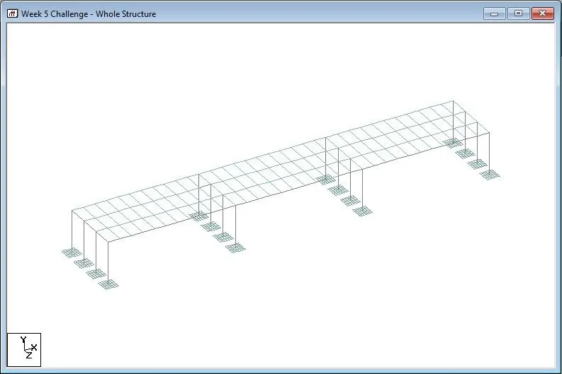
- We will first model a simple bridge whose height is 9m above ground level. Pier size will be 1.5 x 1.5m as given. Loation has been set for Mumbai.
- All other dimesions of the bridge will be assumed as per best engineering practices.
- Using simple Staadpro Commands, the following bridge was designed having 15m width with adjacent piers at 5m distance each.
- Span was set at 30m. For the purpose of this analysis, 3 spans of 30m each was designed using translational repeat command.
- For the superstructure, each 30m girders were divided into 10 parts by using insert node command and taking n=10. Having done this, a mesh was created on which plates were inserted.
- For the foundation, 0.5m meshing was done for total 3x3m footing.
The Image below shows the Model:
In the Utilities tab, the following checks were performed:
Node tools: Orphan nodes and duplicate nodes were removed.
Beam tools: Zero length beams, Duplicate Beams and Overlapping Colinear Beams, if any, were removed.
Plate tools: Duplicate Plates, Warped plates and Plate Connectivity issues, if any, were checked/removed.
Step 2: Specifications
1. Supports
- We begin applying specifications on the Model starting ewith the support criteria for the structure.
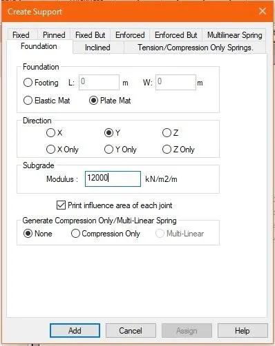
- To do this, we will first press the "Fixed" support button. A dialogue box "Create Support" shall open.
- From the tabs on top we then choose "Foundation".
- Since we have applied plates to our footing, we will select "Plate Mat."
- Direction will be taken in Y direction and we will thus select Y in the Direction checkbox.
- For Subgrade Modulus, we will assume Modulus of 12000 kN/sqm/m.
The image below shows the described actions as above:
- We then press Add and the "Supports - Whole Structure" prompt box will open.
- We select the new support created and then use the plate Cursor from Select tab to highlight all the plates in the foundation.
- We then select "Assign to Selected plates" and assign.
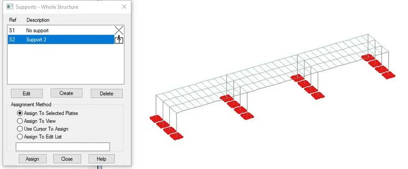
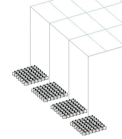
Support Specifications are thus complete. We now move to the next set of specifications.
2. Members
a. Piers
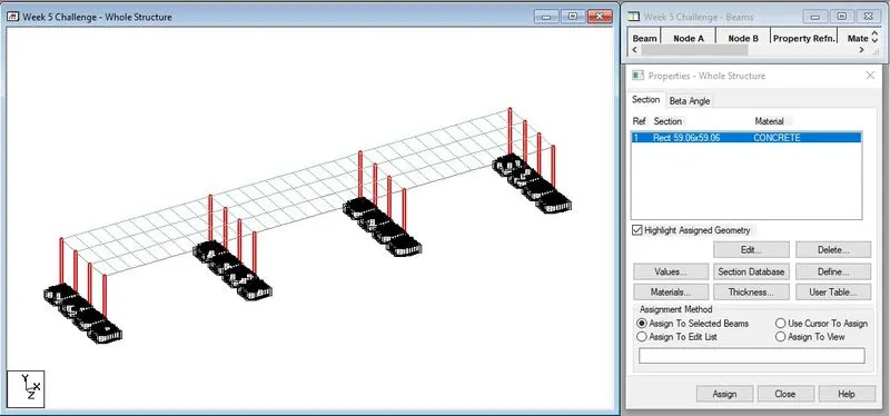
- We begin member specifications with piers.
- We select the "Prismatic" option from the ribbon. The propoerty dialogue box will open as shown below.
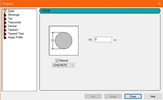
- Here we will go for 1.5 x 1.5m as given to us. For this we will select the "Rectangle" property from the list.
- Material will be Concrete.
- We then press Add.
- Using the Beam Cursor from the Select tab, we will highlight the piers.
- We will then select "Assign to selected beams" in the "Propoerties - Whole Structure" dialogue box.
- We then click Assign>Yes.
b. Girders
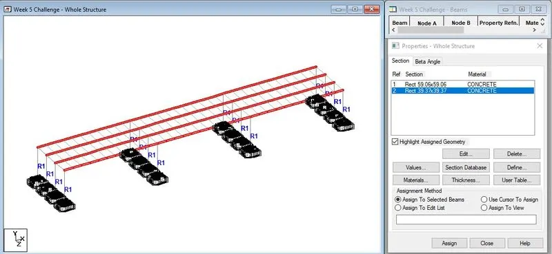
- For the girders in this model, we shall provide rectangular girders of 1 x 1m.
- For this we shall press the Define button in Property - Whole Structure dialogue box.
- Choosing the Rectangular tab in the Property Box, we enter 1m for both YD and ZD.
- Material will be Concrete.
- We click Add.
- Using Beam Cursor we highlight all the girders and select "Assign to Selected Beams">Assign.
c. Cross Girders
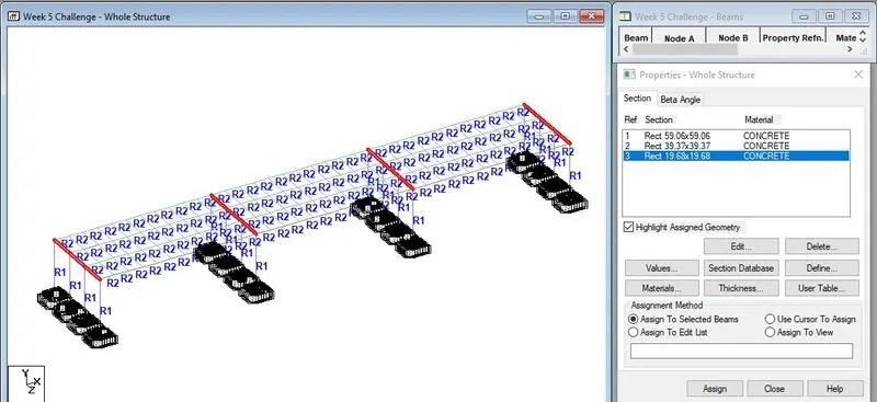
- For the cross girders in this model, we shall provide rectangular girders of 0.5 x 0.5m.
- For this we shall press the Define button in "Property - Whole Structure" dialogue box.
- Choosing the Rectangular tab in the Property Box, we enter 0.5m for both YD and ZD.
- Material will be Concrete.
- We click Add.
- Using Beam Cursor we highlight all the cross girders and select "Assign to Selected Beams">Assign.
d. Deck Slab
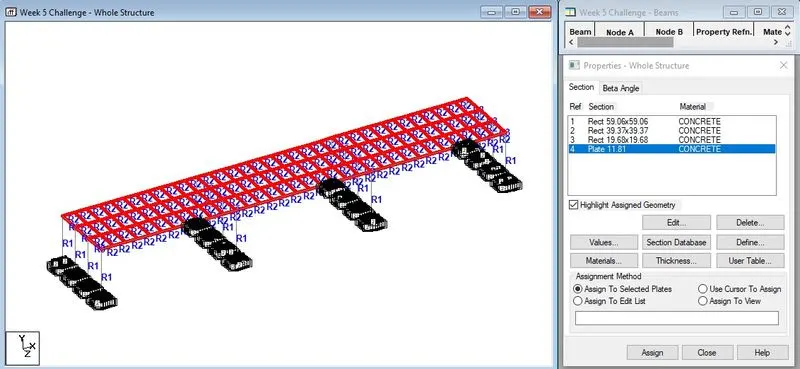
- For the plates representing the deck slab in this model, we shall provide plate thickness of 0.3m thickness.
- For this we shall press the thickness button in "Property - Whole Structure" dialogue box.
- The Plate Element Property prompt box will appear where we will enter 0.3m on all 4 nodes.
- Material will be Concrete.
- We click Add.
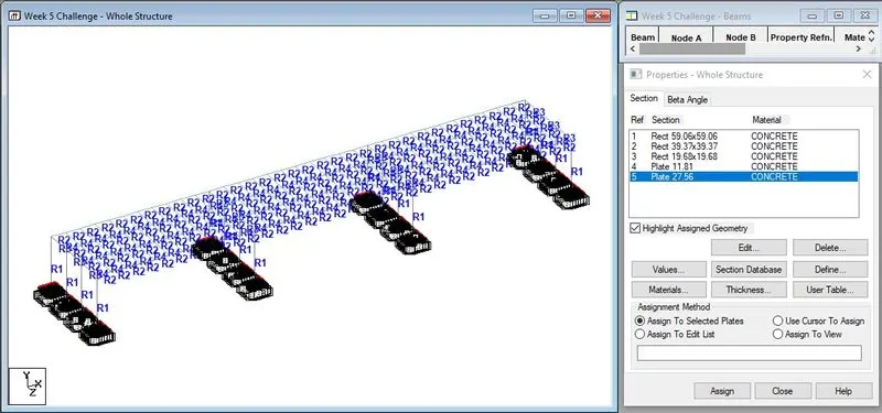
- Using Plate Cursor we highlight all the plates on the deck slab and select "Assign to Selected Plates">Assign.
e. Foundation
- For the plates representing the foundation in this model, we shall provide plate thickness of 0.7m thickness.
- For this we shall press the Thickness button in "Property - Whole Structure" dialogue box.
- The Plate Element Property prompt box will appear where we will enter 0.7m on all 4 nodes.
- Material will be Concrete.
- We click Add.
- Using Plate Cursor we highlight all the plates in the foundation and select "Assign to Selected Plates">Assign.
Step 3: Loading
a. For Piers:
In order to calculate Wind Loads, we will have to convert the wind pressure Pz = 2.57 kN/sqm to UDL.
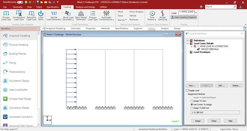
For the Piers of dimension 1.5x1.5m, only one face will be exposed to the wind at a time and we will multiply 1.5m of Pz to get 3.855 kN/m.
We will use this value to calculate the Wind Load on Piers.
- After pressing the Loading Tab, The Load Definition Dialogue Box opens.
- We then select Load Case Details and then click Add.
- We give the Title as "Wind Load in +Z Direction." We then click Add.
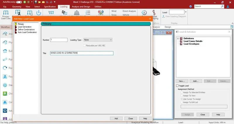
- After this we click on the newly created load case and click Add.
- For this loading we will choose Member load and then Uniform Force i.e. UDL.
- We will then enter the value 3.855 kN/m as force (W1) and select the Global Z Direction.
- We then click Add.
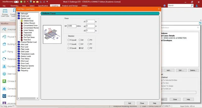
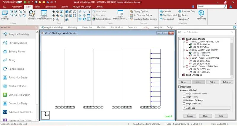
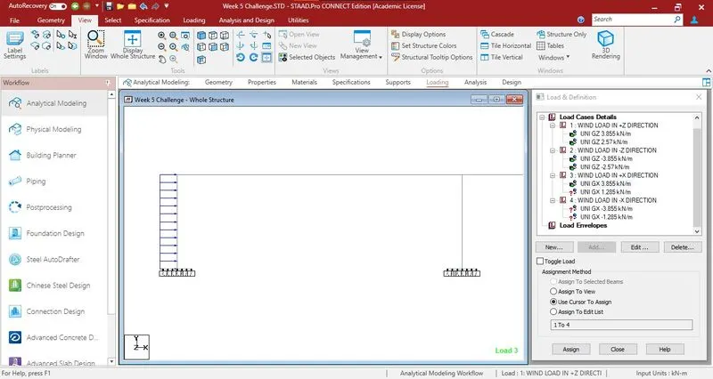
- We now use the Beam Cursor to Select all the Piers facing the Glabal Z direction and Assign the selected beam to the new load envelop created.
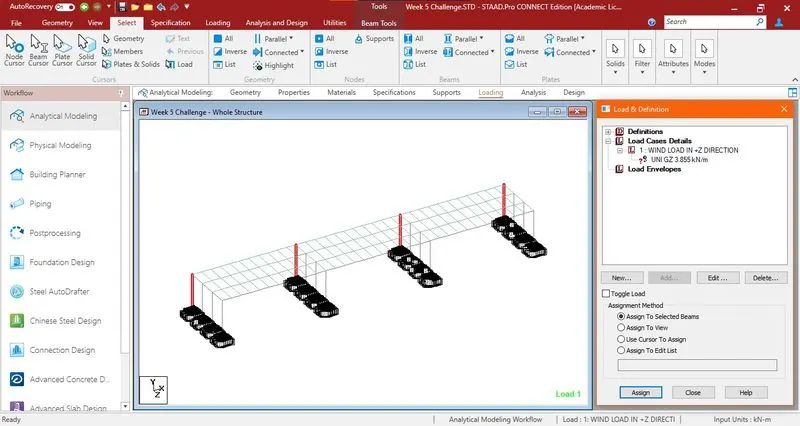
- To check the Loading we select the cross sectional view from the view Tab and then select "View Loading Diagram" in the Loading Tab.
- The Loading Diagram will be displayed as below.
b. For Girders
For the Girders of dimension 1.0x1.0m, only one face will be exposed to the wind at a time and we will multiply 1.0 m to Pz to get 2.57 kN/m.
We will use this value to calculate the Wind Load on Girders.
- Once again we click on the newly created load case "Wind Load in +Z Direction" and click Add.
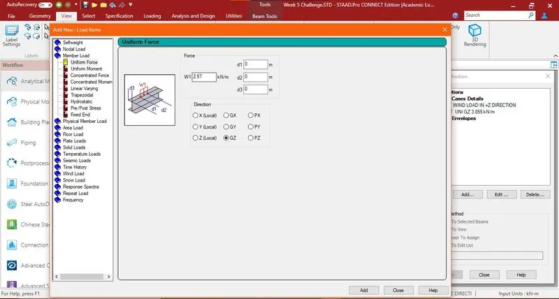
- For this loading we will again choose Member load and then Uniform Force i.e. UDL.
- We will then enter the value 2.57 kN/m as force (W1) and select the Global Z Direction.
- We then click Add.
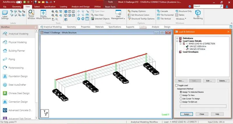
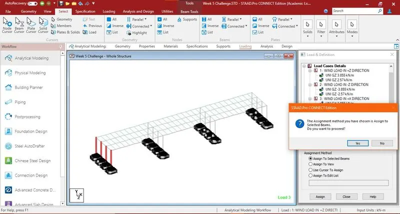
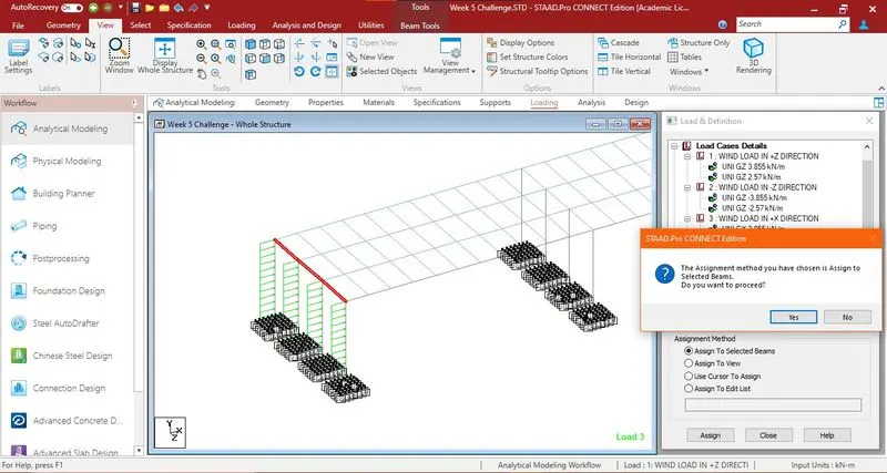
- We now use the Beam Cursor to Select all the Piers facing the Glabal Z direction and Assign the selected beam to the new load envelop created.
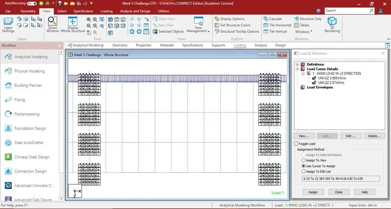
- To check the Loading we select the Top view from the view Tab and then select "View Loading Diagram" in the Loading Tab.
- The Loading Diagram will be displayed as below.
- We will now repeat the above Steps again for the genration of 3 more Load Case Details viz. -Z Direction, +X Direction and -X Direction.
- We will then apply the same loads on the Piers and Girders but only the direction will be changed.
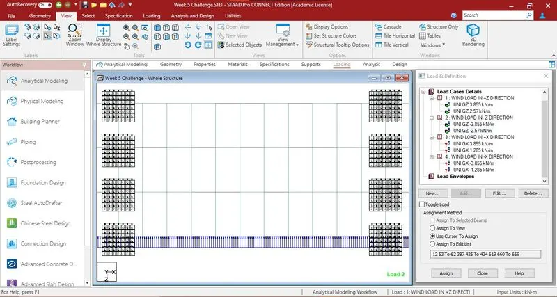
- For the +X and -X Directions, the cross girders are of 0.5 x 0.5m. Accordingly, UDL applied will be 0.5 x Pz = 0.5 x 2.57 = 1.285 kN/m.
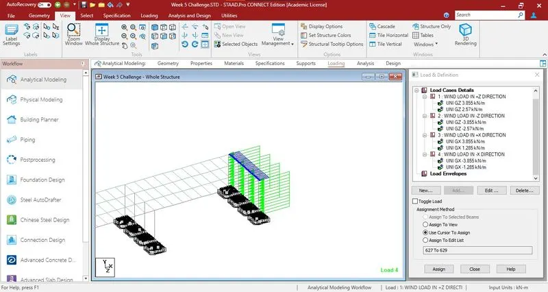
- Shown below in the Load Definition Dialogue Box all the new load details and their corresponding envelops created similarly as described in the previous steps.
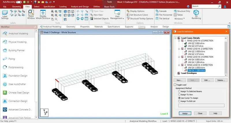
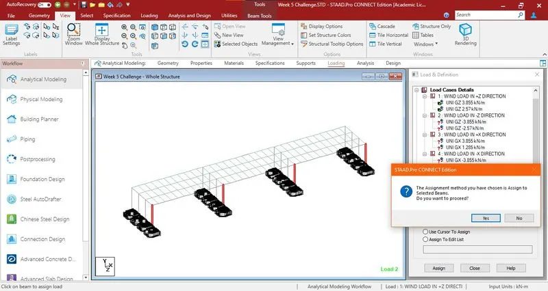
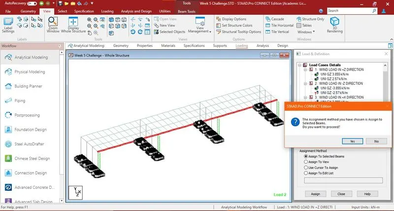
- We will now apply all the relevant members to the corresponding load envelopes.
- The Final Load Diagram After application of Wind Load from all four directions are shown below.
Step 4: Analysis and Design
- We are now ready to run the file.
- We will first click Define Commands and add the "Perform Analysis" command to the command file.
- We now Run Analysis.
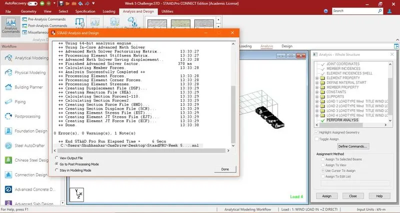
- Zero Errors and Zero Warning for this Model.
Results
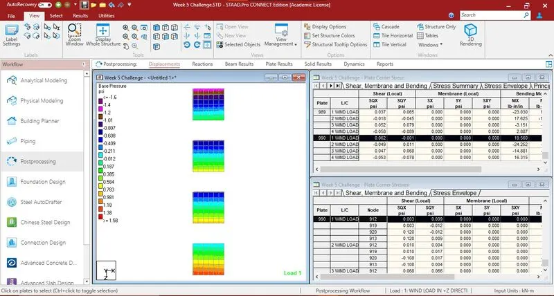
Load Case 1: Wind Loads in +Z Direction
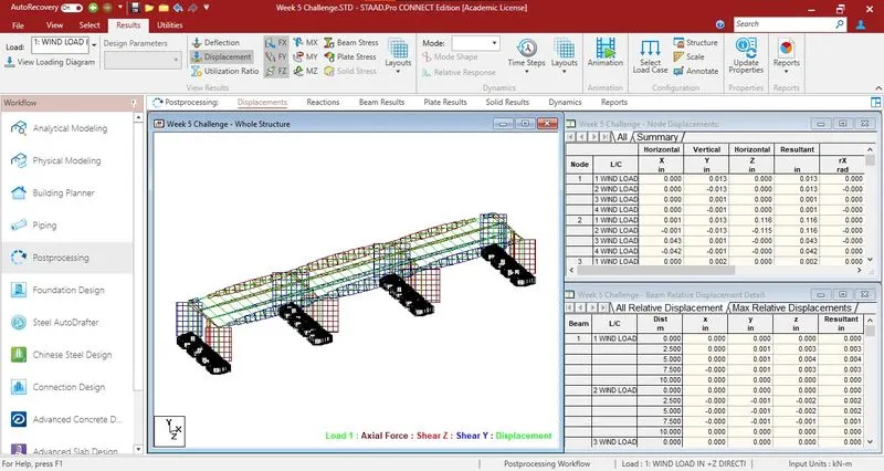
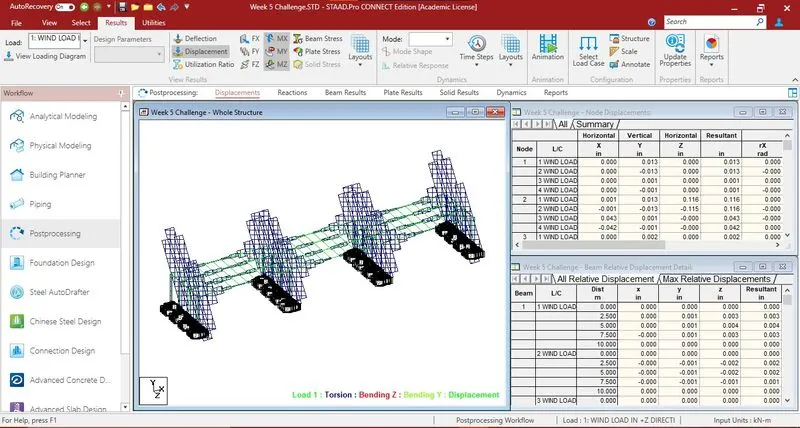
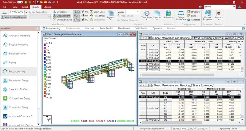
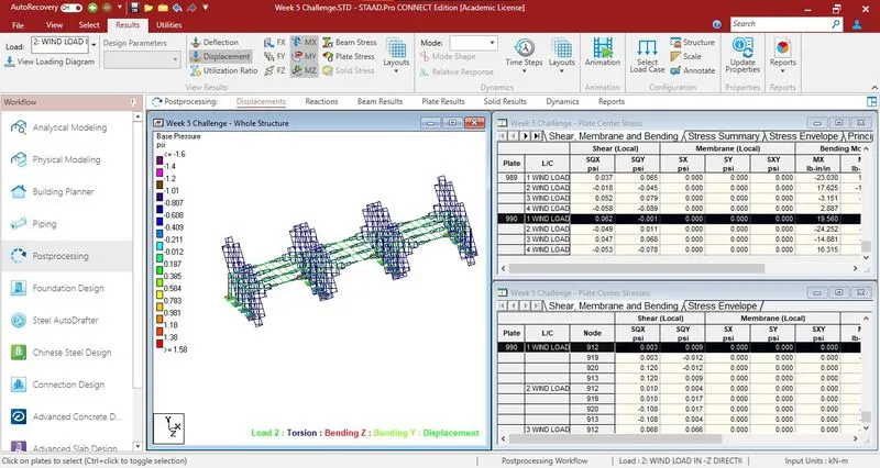
Load Case 2: Wind Loads in -Z Direction

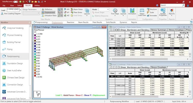
Load Case 3: Wind Loads in +X Direction
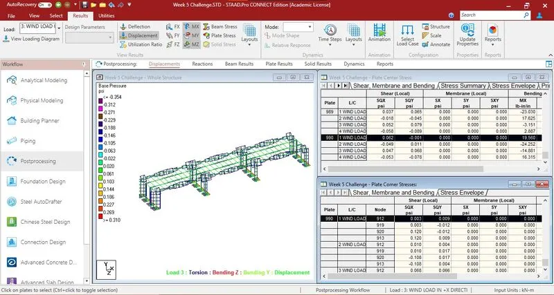
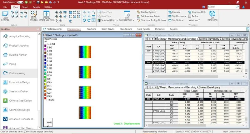
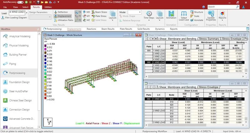
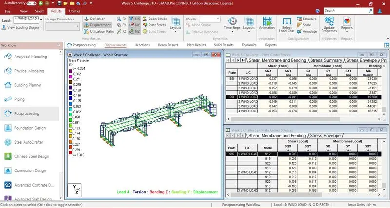
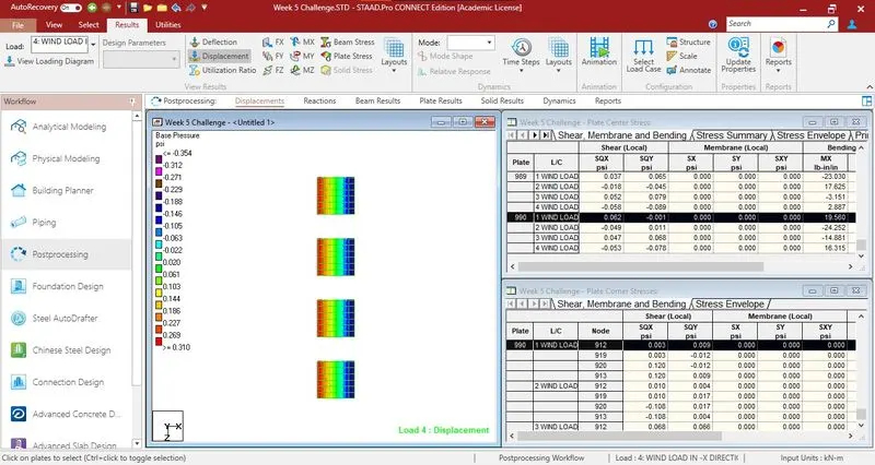
Load Case 4: Wind Loads in -X Direction