Week 11 Challenge
Aim
To calculate the Temperature Load on a Bridge in Delhi as shown below and applying the calculated loads on the StaadPro model.
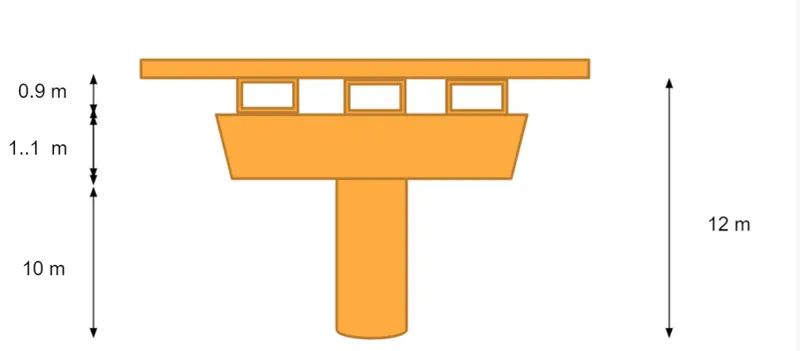
Data Provided:
- Location of the bridge is Delhi
- Type of Bridge is RC Bridge
- Grade of concrete = M40
- Box Girder Bridge of (1.5 x 1.5)m
- Web thickness = 0.3m
- Diameter of the pier = 2.5m
- Deck slab width = 7.0m
- Width of pier cap = 6.0m
- Thickness of deck slab = 550 mm = 0.55m
Introduction
The daily and seasonal fluctuations in air temperature, solar radiations etc causes the following:
- Effective bridge temperature : Changes in overall temperature of bridge.
- After a period, there will be a minimum and maximum with a range of effective bridge temerature.
- This results in load and load effects.
The load effects are due to:
- Temerature restraints : Restraints offered for expansion or constraction by form of construction.
Eg. Portal frame, arch, flexible pier, elastometric bearings etc.
- Frictional bearing restraint : Friction at roller or sliding bearings
- Temperature difference: Difference in temperature between the top surface and other levels through the entire height of the superstructure.
- Positive Temperature difference : During solar radiations, gaining heat on top surface of superstructure.
- Reverse temperature difference : Loss of temperature on top surface of superstructure as a result of radiation and other effects.
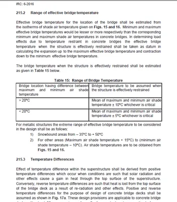
As per IRC 6-2016, table 15, shows the range of bridge temperature as illustrated below.
For the purposes of calculating temperature effects, the coefficient of thermal expansion
for RCC, PSC and steel structure may be taken as 12.0 x 10⁻⁶/deg C.
Tensile stresses resulting from temperature effects not exceeding in the value of 2/3rd of modulus of rupture may be permitted.
Sufficient amount of non tensioned steel shall be provided to control thermal cracking.
Procedure
Manual Clculation:
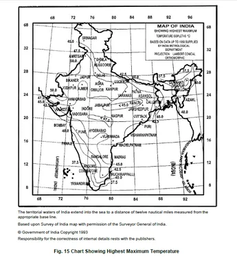
Maximum temperature in the loacation as per IRC :6-2016 = 47.5 degree
Minimum temperature in the location as per IRC :6-2016 = 0 degree

- Effective temperature difference = (47.5-0)/2+10 = 33.75 degree celcius
- Stress due to temperature = αδT E = 11.27 x 10-6 x 47.5 x 5000 x sqrt (40) = 16.92 kN/m2
- Maximum permissible stress = 2/3 x 0.7 x sqrt (fck) = 2/3 x 0.7 x sqrt (40) = 2.95 kN/m2
Hence stresses are restricted to 3kN/m2
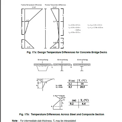
- Positive temperature difference :
Temp at top = 47.5 degree celcius
Temp at bottom = 2.1/17.8 x 47.5 = 5.603 degree celcius (as per IRC - 6, Fig. 17a: Design Temperature Differences for Concrete Bridge Decks)
This temperature variation is applied as loading in the StaadPro model.
Modelling in Staad.Pro:
Modelling
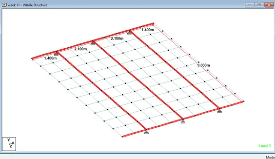
- Deck of the bridge is modelled as per the given data.
- Deck of the bridge spanning for 9.0m and width 7.0m with three box girders of 1.5 x 1.5m . Deck of the bridge thickness is given as 0.55m.
- Simple supports are assigned in the places where the box girder rets over the bearing of the pier cap by using the option, Supports > create > pinned > add > assign to selected nodes
- Mesh of size (0.9 x 0.7)m is assigned all over the deck slab.
Specifications
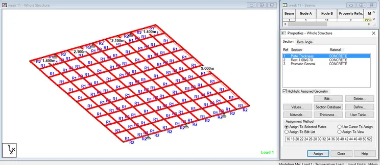
1. Deck Slab
- Properties of various structural elements are assigned using the following option
General > thickness > add > 0.55m (deck slab thickness) > add > assign to selected plates for deck slab
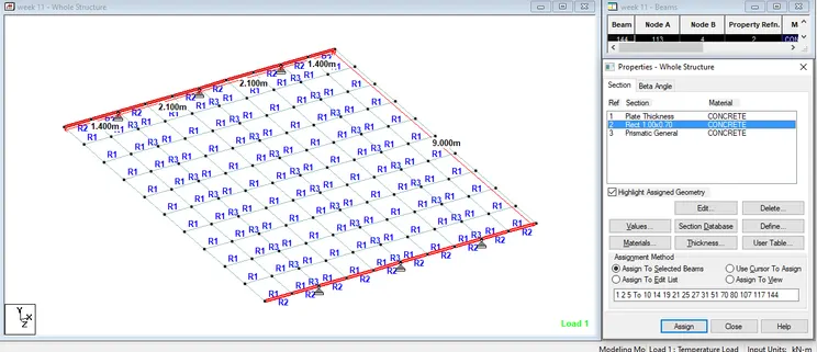
2. Cross Beams
General > Define > rectangular > 1.00m x 0.7m (assumed dimensions of cross beams) > add > assign to selected beams for cross beams.
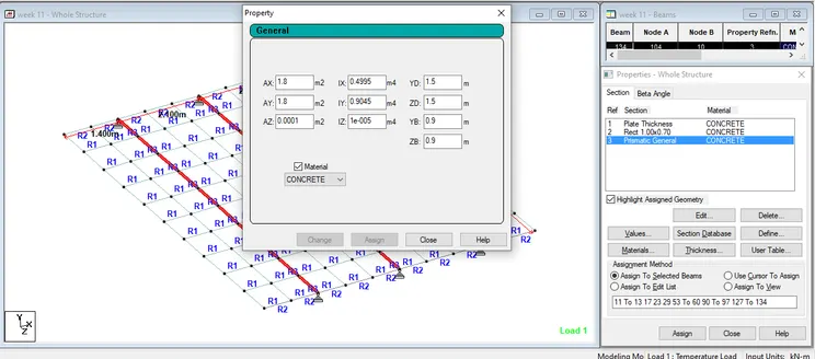
3. Box Girder
- Properties of the box girder is assigned as a prismatic beam with the following details.
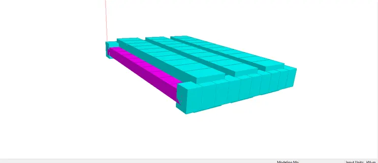
4. 3D Rendering
The 3D rendered view is shown below
Loading
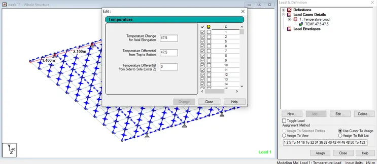
Upon successful modelling and assigning properties to all the elements, we now load the bridge with temperature loads by using the option,
- General > Load case details > add > change load case 1 to temperature loads, type: Live load > add
- Load case details > Temperature load > add > temperature load > assign to view
Analysis
After applying the load, model is analysed using the option,
- Commands > Analysis >Perform analysis > OK
- Analyse > Run Analysis > ok
Results
We now go to post processing mode to view the results.
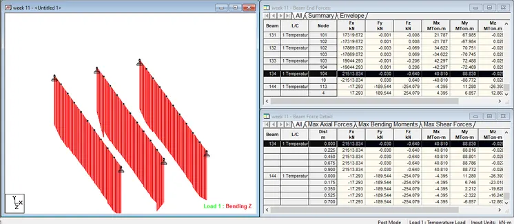
Maximum Bending moment Mz in Longitudinal girders are obtained by selecting the girder.
Report > section forces > Moment Mz > low to high (sagging moment) > ok
BMmax = -0.033 Mton-m for beam no. 97
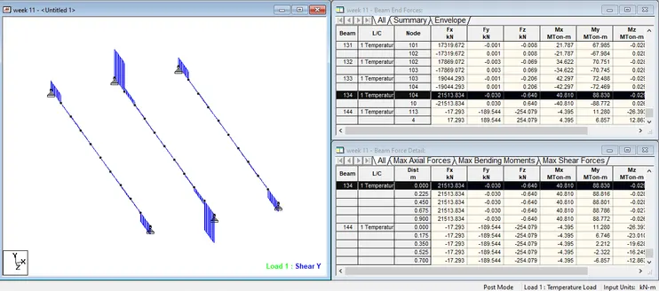
Maximum Shear force Fy in Longitudinal girders are obtained by selecting the girder.
Report > section forces > Shear Y > ok
SFmax = 0.102 kN for beam no. 12.
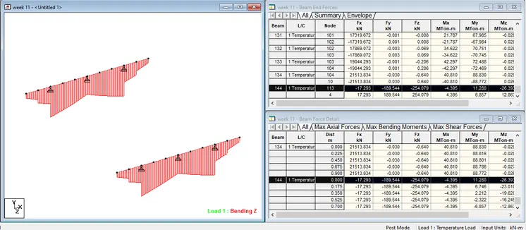
Maximum Bending moment Mz in cross girders are obtained by selecting the girders
Report > section forces > Moment Mz > low to high (sagging moment) > ok
BMmax = -87.27 Mton-m for beam no. 6.
Maximum Shear force Fy in Longitudinal girders are obtained by selecting the girder.
Report > section forces > Shear Y > ok
SFmax = 189.54 kN for beam no. 31.
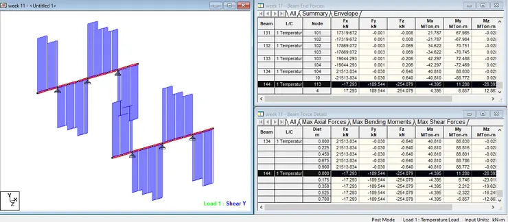
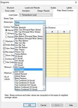
Bending stress in x and y in plate is obtained by using the option plate results option in post processing mode.
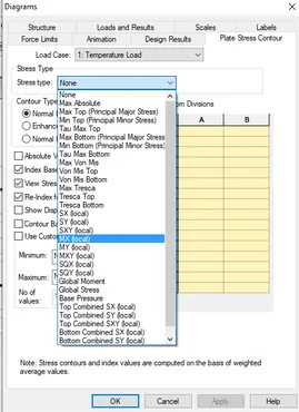
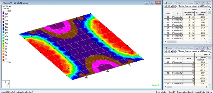
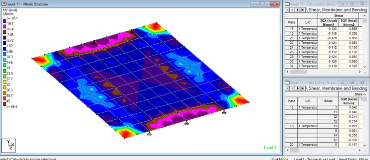
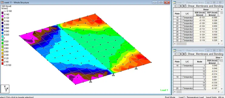
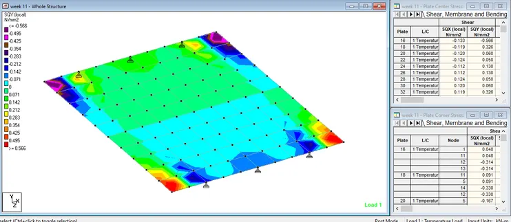
Shear stresses in x and y direction are obtained similarly