Week 4 Challenge
Aim
To calculate the Earthpressure acting on the abutṁent wall and applying on the staadpro.
Introduction
Unit Weight of Soil
- Unit Weight of Soil is defined as the total weight of soil mass W per unit of total volme V.
γ = W/V - Dry Unit Weight: It is defined as the weight of dry soil Ws per unit Vome V.
γd = Ws/V - Saturated Unit Weight: It is the ratio of Weight of fully saturated soil Wsat to its total volume V.
γsat = Wsat/V - Submerged unit weight: It is equal to saturated unit weight minus unit weight of water.
γ = γsat - γw
Soil Report and Borehole Drawing
- Soil Report: It is the report which contains detailed infromation about the soil layers present in the site and the various test results showing the shear strength c and ϕ parameters, N values and ground water table level.
- It provides the Safe Bearing Capacity values based on the test conducted on soil samples.
- Borehole diagram is provided in the soil report.
- Borehole Diagram: It is the diagram which shows the type of soil layers variations with propoerties below ground level till the termination level of borehole.
- It indicates the ground water table level and RL of starting and ending of different types of soil present below ground level.
Earth Pressure
- Earth Pressure: It is the horizontal thrust exerted by the retained earth on a vertical structural element like wall, pier, abutment, etc.
- Three conditions exist as follows:
- Earth Pressure at rest
- Active Earth Pressure
- Passive Earth Pressure
Earth Pressure at rest:
- When the vertical structural member is rigid and unyielding, the soil mass is in a state of rest and there will be no deformations and displacement.
- The Earth pressure corresponding to this state is Earth Pressure at rest.
Active Earth Pressure:
- When the vertical structural member moves away from the backfill, the soil mass expands and there is a decrease in pressure.
- The Earth pressure corresponding to this is state is called as Active Earth Pressure.
Passive Earth Pressure:
- When the vertical structural member moves towards the backfill, the soil mass is compressed and the shear resistance developed towards the vertical member and there is increase in pressure.
- The Earth pressure corresponding to this state is called as Passive Earth Pressure.
Procudure
Calculation of Soil Loads on Abutments and Piers
- Calculate the Earth pressure on the bridge shown below:
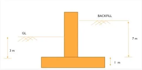
Given:
Abutment Wall = 5m length
Backfill of Soil = 7m height
Ground level = 3m above foundation level
Water Table = 3m above foundation level
Structure is submerged till ground level.
Taking Coefficient of Active Earth Pressure ka = 0.35, taking γ = 18kN/cu m
We know γ = γsat - γw
implies γsat = γ + γw, where γw = unit weight of water = 9.81 kN/cu m
implies γsat = 18 + 9.81 = 27.81
Soil Loads on Piers:
The Earth Pressure is calculated as shown below:
- K1 = ka.γsat.h1
Here h1 = 3m (submerged), K1 will determine pressure at the outer side of pier where no backfilling is done. So, only ground level pressure will be incorporated.
Hence, K1 = 0.35 x 27.81 x 3
K1= 29.20 kN/sq m - K2 = k0.{(γsat x h1) + (γ x h2)}
Here h2 = 4m, K2 will determine pressure at the inner side of pier where backfilling is present. So, backfilling pressure will be incorporated. k0 is taken as 0.5 for earth pressure at rest.
Hence, K2 = 0.5 x {(27.81 x 3) + (18 x 4)}
K2 = 77.72 kN/sq m
Soil Loads on Foundation:
We calculate the soil loads on the foundation of the bridge shown below:
Taking γ = 18 kN/cu m
The soil loads on the foundation is calculated below:
- P1 = γ x h
P1 is pressure on outer side of foundation where backfilling is absent and therefore only pressure due to grond level filling (3m) will be incorporated. Since soil is submerged till ground level, we will use γsat which is unit weight of submerged soil and h1 = 3 m
So, P1 = γsat x h1
P1 = 27.81 x 3
P1 = 83.43 kN/sq m - P2 = γ x h
P2 is pressure on inner side of foundation where backfilling is present and therefore pressure due to ground level filling (3m) and backfilling (4m) will be incorporated (total 7m). Since soil is submerged till ground level, we will use γsat which is unit weight of submerged soil for h1 = 3m and γ which is unit weight of soil for h2 = 4m.
So, P2 = (γsat x h1) + (γ x h2)
P2 = (27.81 x 3) + (18 x 4)
P2 = 155.43 kN/ sq m
Uplift Pressure:
We calculate the uplift pressure on the bridge as shown below:
- The uplift pressure is calculated as follows
The hw is taken from water table level to the bottom of the foundation.
Pu = γw x hw
Here hw is 3m + 1m
Pu = 9.81 x 4
Pu = 39.24 kN/sq m
Inclined Backfill & its Earth Pressure:
In most case, backfilling is not horizontal. Immediately after construction, the backfill tends to become inclined especially in hilly areas.
For this problem, we will make the following assumptions:
- Angle of internal friction ϕ is 27 degrees.
- The clination of the backfill α is 15 degrees.
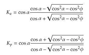
Here ka = 0.22
For backfilling of more than 6m, we will have a huge earth pressure. during such time, it is more economical to use inclined backfilling.
Inclined Earth Pressure = ka x γ x h
= 0.22 x {(27.81 x 3) + (18 x 4)}
= 34.19 kN/sq m
We will now use these various values obtained in Staadpro analysis and study the results.
Analysis in StaadPro
For the purpose of this analysis, we are creating a simple model of 10m single span and 5m width. height of Pier is taken as 10 m since backfilling is 7m.
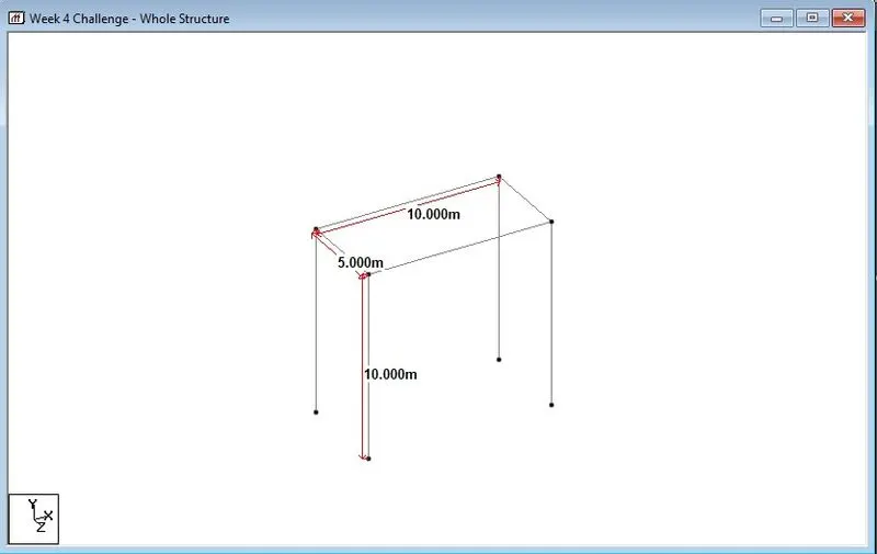
Since we are designing the foundation, we will add plate elements to the foundation whose foot is 1m thick (given)
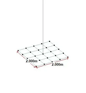
After selecting the bottom nodes in the pier, we will use translational repeat command and create a mesh of 0.5m around the node. Since no information of width of foundation footing is given, we will assume a dimesion of 2x2m and 1m thickness.
The image below shows the meshing on one pier foot.
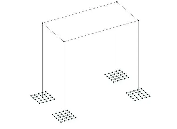
We will now copy this mesh on the remaing piers be using copy and paste command.
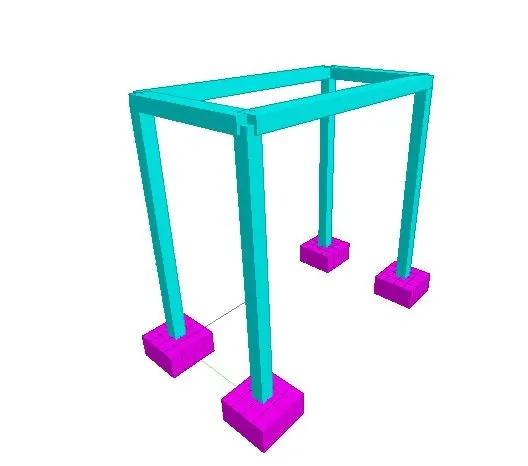
For the purpose of specifying properties of piers and girders, we assume pier dimensions as 0.5mx0.5m and top four girders as 0.5mx0.7m. A 3D rendered view is displayed below:
Since we wont be applying live loads on the structure, a simple plate is placed as deck slab of 0.35m thickness.
In this analysis, we will use plate mat for the support criteria.
We go to Specification > Support
The support prompt will open. We then go to the foundation tab and select "Plate Mat" as shown below:
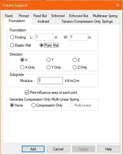
Here, Direction will be in Y direction. Subgrade modulus is taken from the soil report which is SBC divided by maximum settlement. For this problem, we are assuming a value of 12000 kN/sqm/m as Subgrade modulus.
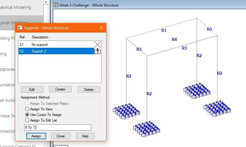
Loading:
Now will begin loading. For this we will go to Loading and then we will click Load Cases Details. We will click Add button and the Add New : Load Cases dialogue box will open.
Here in the Primary Load cases details we will give the Title as "Earth Pressure."
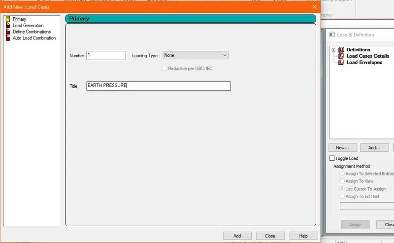
We then click Add > Close.
Now we click on the newly created "Earth Pressure" and click Add to give the details.
The Add New:Load Item dialogue box will open. In this case, we will select the Member Loads because the forces are acting on the piers. We will then select Linear Varying option.
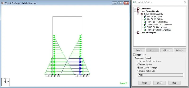
We had calculated K1 = 29.2 kN/sqm and K2 = 77.72 kN/sqm
Since the input in varying load in in kN/m, we will assume running metre as 1m. This makes W1 = 0 kN/m and W2 = 29.2 kN/m for K1 and W1 = 0kN/m and W2 = 77.72 kN/m for K2
Using these values we add two load details for K1. One in local Z direction and one in local -Z direction.
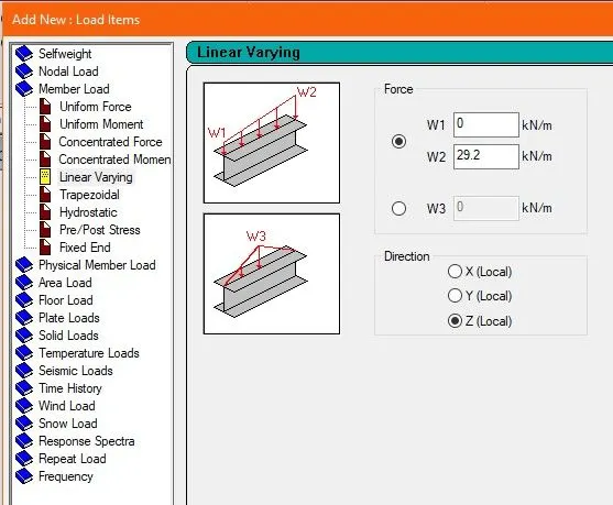
The load applied for K1 is shown below:
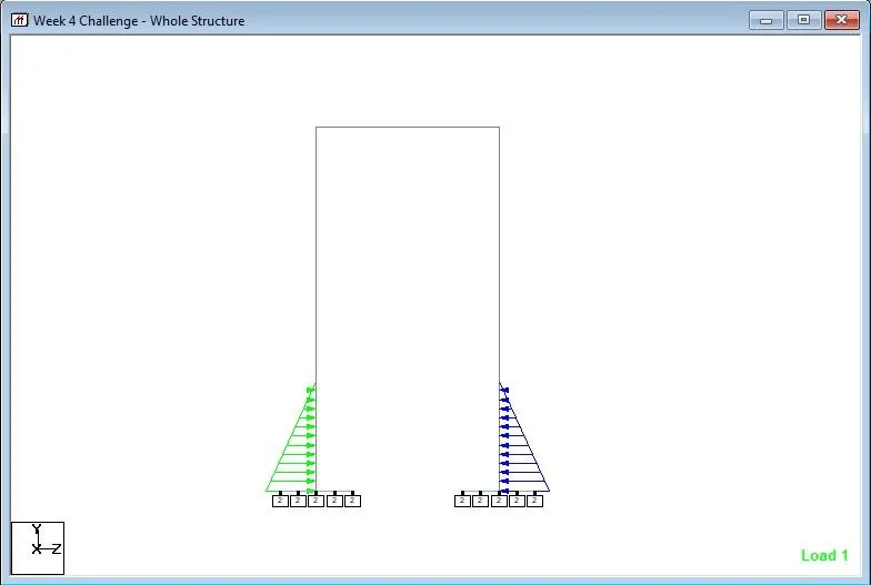
As we have manually calculated above, the horizontal forces acting on the piers are K1 and K2. These forces are acting at 3m and 7m respectively from the top of the foundation footing. Two nodes will need to be inserted at 3m and 7m from the bottom node so as to apply the loads K1 and K2 in those sections respectively.
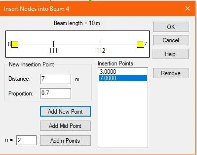
For K2, we will have to select Hydrostatic option from Member Loads because of varying nodes.
We apply the loads K2 on the backfilling portion and we assign to the relevant members as per local Z direction. Below is the cross setional view of both K1 and K2 loads applied.
We will now perform analysis:
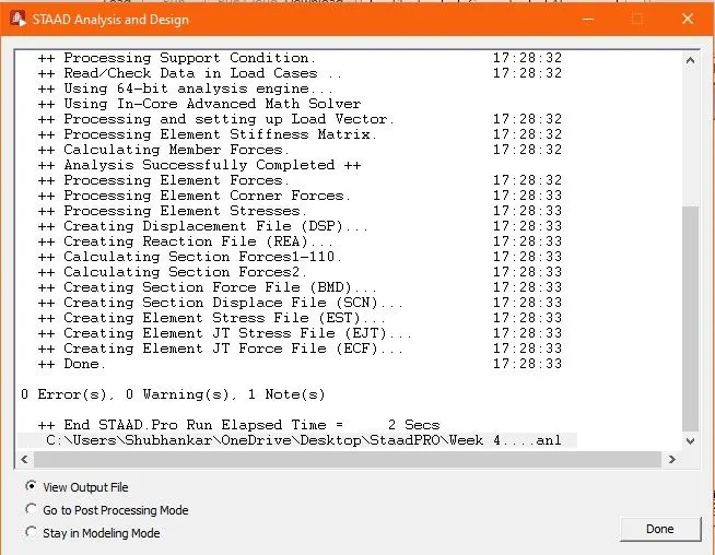
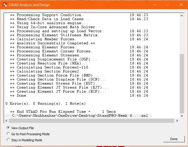
Zero Errors and Zero Warnings for this Analysis.
Next we need to apply loads on the foundation. We had found values P1 and P2 in the Manual Calculation above.
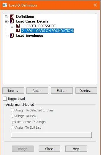
Once again we will go to Load Case Details and Define a New Load Title called "Soil Loads on Foundation" as shown below:
We now click on Add button followed by "Plate Loads" and then "Pressure on full plate".
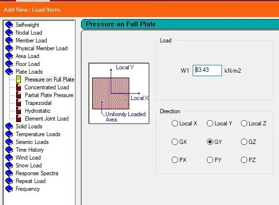
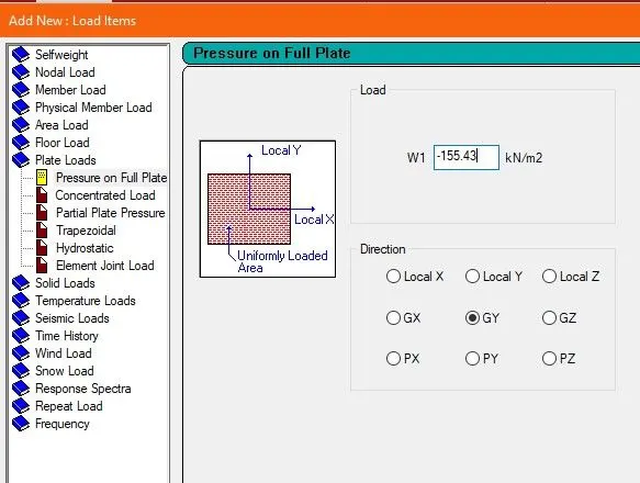
We had calculated two values namely P1 = 83.43 kN/sqm and P2 = 155.43 kN/Sqm. We will therefore need to add two load cases. We will select the Global Y direction for both Load Cases.
For P1:
For P2:
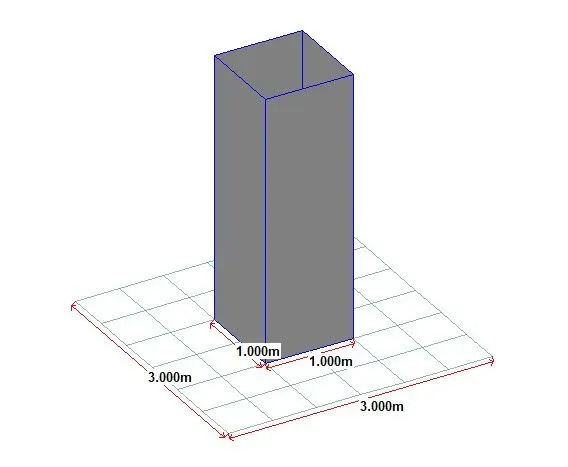
For the Plate Loading, we will have to make a few changes in the structure. The dimensions of the piers will be changed from 0.5mx0.5m to 1mx1m so that the pier sits properly on each 0.5m plate and loading can be applied properly. The diamer of the footings will also be changed from 2mx2m to 3mx3m.
After the relevant changes, the foundation appears as shown below:
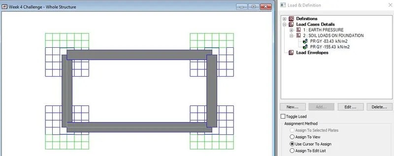
The outer parts of the foundation plates will be assigned P1 loading whereas the inner plates will be assigned P2 loading.
A top view after assigning plate loads is seen below:
Once again we run analysis:
Results Obtained:
1. For Load Case: Earth Pressure
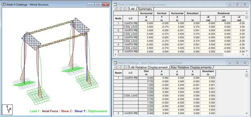
Deflection of Members in Fx, Fy, Fz directions
The Deflection of the Members can be seen in the following image:
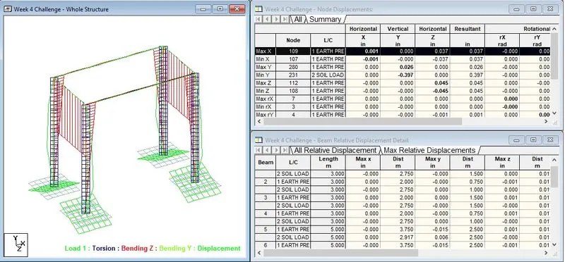
Deflection of Members in Mx, Yy, Mz directions
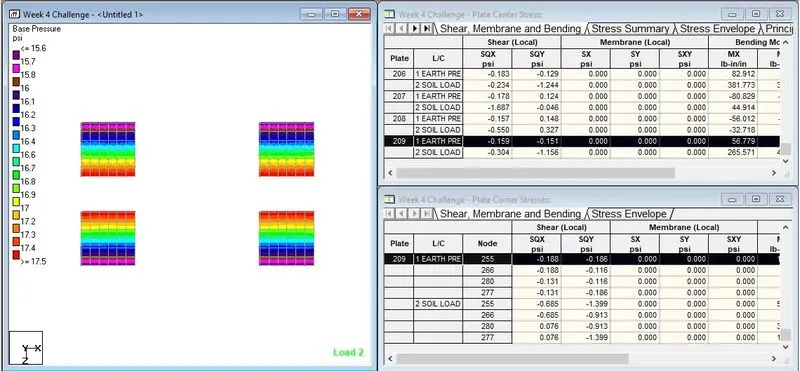
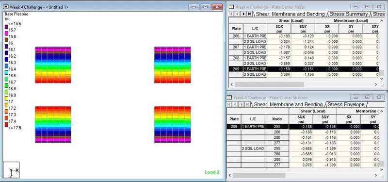
Base Pressure in Foundation
2. For Load Case: Soil Loads on Foundation
Deflection of Members in Fx, Fy, Fz directions
The Deflection of the Members can be seen in the following image:
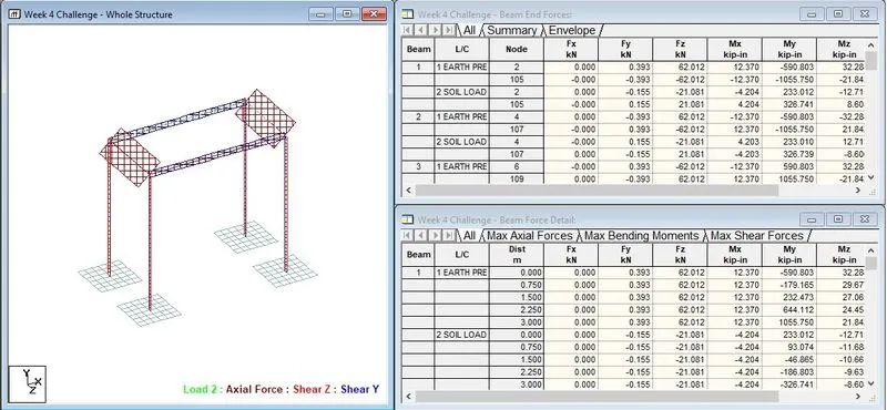
Deflection of Members in Mx, Yy, Mz directions
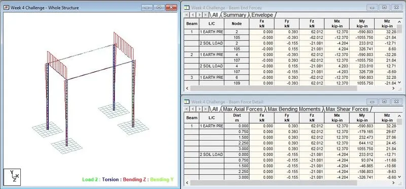
Base Pressure in Foundation