Week 3 Challenge
Aim
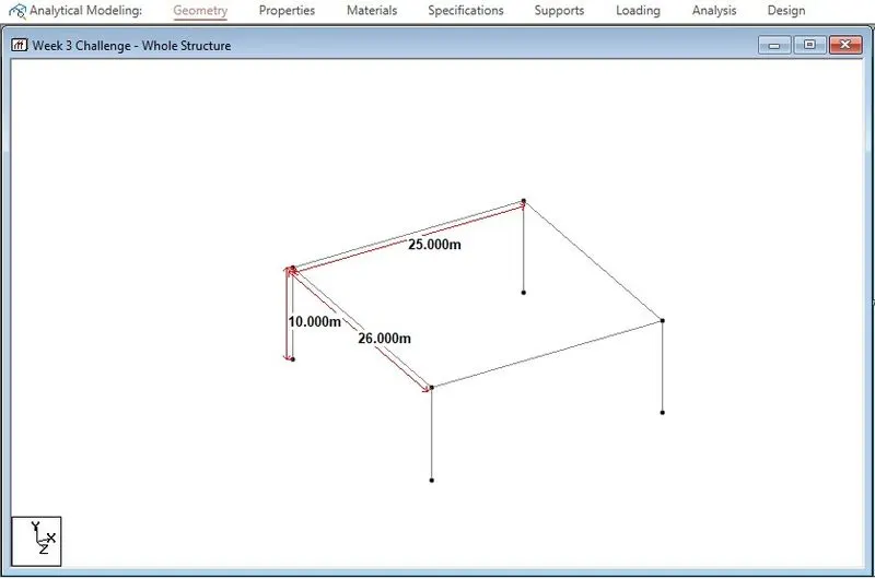
For the I Girder bridge to be designed for the following data, the centre to centre distance of piers along the width of the bridge deck is 26m , Span of the bridge is 25m, Pier height is 10m, Apply the IRS railway loads and model in Staad pro and perform the structural analysis.
Introduction:
In Week 3, we are introduced to IRS, that is, Indian Railway Standards. The lessons taught in this Week were:
- Introduction to Indian Railway Standards (IRS) Code.
- IRS Gauge Calculation.
- Broad Gauge Loading.
- Metre Gauge Loading.
- Metro Rail Loading.
Discussion:
- Introduction to Indian Railway Standards (IRS) Code
- Indian Railway Standards or briefly the IRS Code were developed by Indian Railways for the purpose of designing and construction of Railway related structures.
- The various IRS loads for design of bridges includes
- Metro Rail Loading
- Broad gauge Loading
- Electric Train
- Gauge A and Gauge B Loading
Metro Rail Loading
- Axle Loading = 17 tons
- Maximum No. of cars = 6 nos.
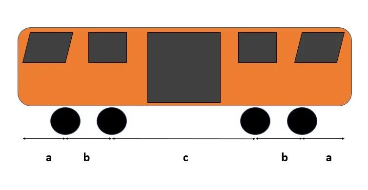
- Wheel Configuration
- Lengh a = 2150mm
- Length b = 2200mm
- Length c = 12400mm
- Length of the car = 21100mm
Broad Gauge Loading
- Here there is no symmetry in loading and distance between wheels also differs.
- The Maximum Axle loading is in the middle wheel portion which is around 19.25 tonnes and Minimum Axle Loading is in the front wheel which is 11.84 Tonnes.
- There is one small wheel followed by four big wheels and then 5 small wheels of differing sizes, distances and axle loading.
- Unlike Metro Loading, Broad Gauge Loading is more complicated.
Electric Train Loading
- Electric Train Loading is nothing but Metre Gauge Loading.
- It has been used for several decades.
- In most cities this has been upgraded to Broad Gauge Loading.
- This is to accomodate more population.
- Each carriage has has six wheels in two sets. One set in front and the other set in the back.
- Distance between two sets is 2743mm while distcance between individual wheels is 914mm
- All three wheels in each set have same Axle Loading of 74.5kN.
- Overall Train Load is 27.8kN if we consider it as UDL.
Gauge A and Gauge B Loading
- Similar to Class A and Class B Loading in IRC, we have Gauge A and gauge B Loading in IRS.
- The maximum axle loading in Gauge A loading is 79.4. kN and minimum axle loading is 58.8 kN.
- Gauge A and Gauge B is also called 762mm Gauge.
- Unlike IRC, IRS has tables for calculation of Shear Force and Bending Moment for different spans between piers.
- Gauge B axle loading is same for all six wheels which is 59.8 kN.
Manual Live Load Calculation of Forces for IRS Metro Rail Loading:
- Live Load Type - Metro Live Loading
- Span L = 25m
- Width of Deck Slab = 26m
The diagram below shows the application of Live Loads on the superstructure:
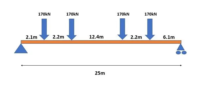
The superstructure is analyzed for the above loading using equilibrium equations
- ∑V = 0
170 + 170 + 170 + 170 = Ra+Rb
680kN = Ra+Rb - ∑Ma = 0
(170 x 2.1) +(170 x 4.3) + (170 x 16.7) + (170 x 18.9) = 25Rb
7140 = 25Rb
Rb = 285.6 kN
Ra = 394.4 kN - Bending moment is calculated as follows:
Ma = 0
Mb = 0
The Bending Moment as Midspan is
Mc = (170 x 4.2) + (170 x 6.4) - (394.4 x 12.5) = - 3128 kNm - The Maximum Bending Moment Due to Live Loading is - 3128 kNm
Analysis in StaadPro:
For the purpose of analysis, we will retain span of structure as 25m and width as 26m
The simple frame of the structure is as follows:
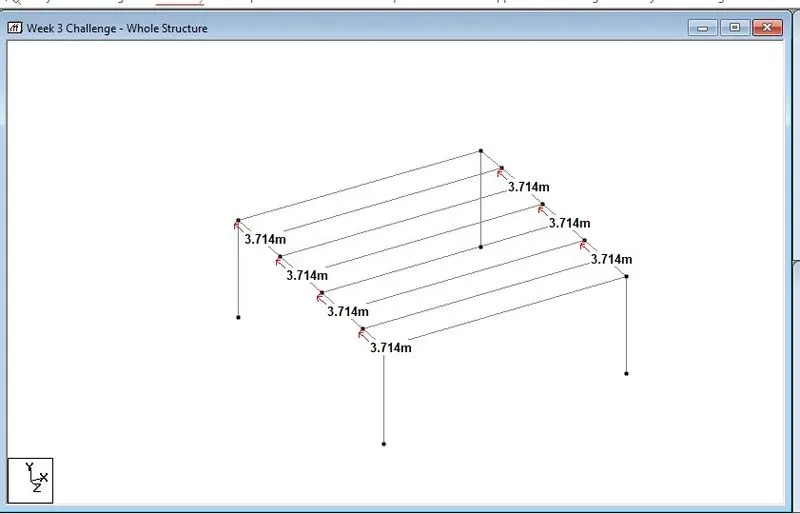
We will place the 8 Girders at 3.714m spacing as follows:
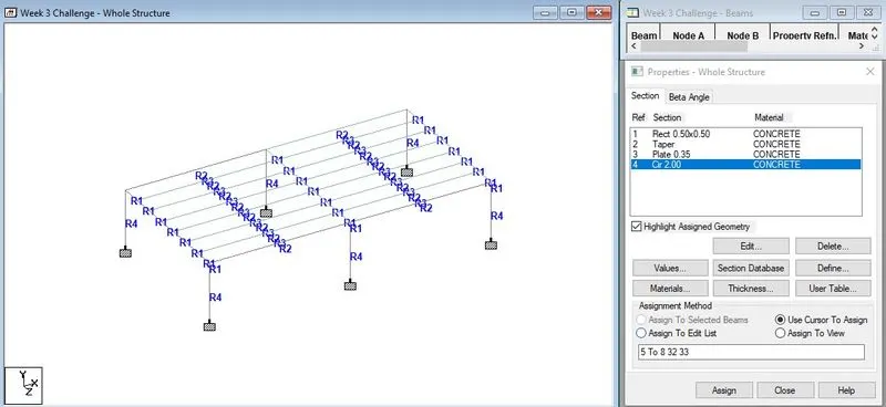
The following specifications were assigned
- Cross Girders = 0.5m x0.5 m
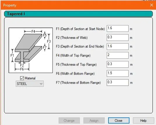
- I Girders (shown in the image below)
- Deck slab 0.35 m
- Pier diameter = 2m
Loading:
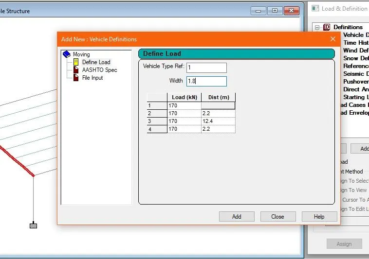
We will assign the Metro Loading in Definition> Vehicle Definitions>Add
Here we will specificy the axle loading in each wheel and distance between wheels as weel as width of vehicle as shown below:
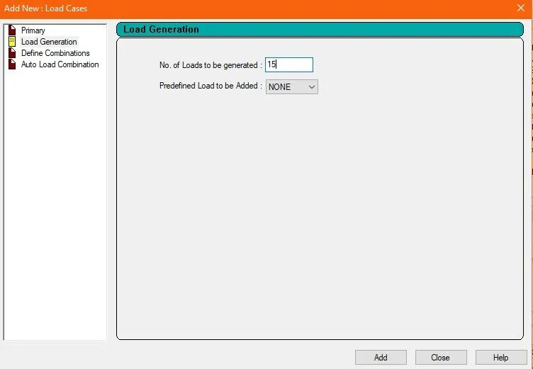
Now we will go to Load Cases Details>Add>Load Generation
Here we will be asked "No. of Loads to be Generated"
This will be found by Adding (Length of Vehicle + Span) / Incrementor no. of iterations
Here as default we are taking 15
After this we will click on the generated load >Add
We will now specify the starting point of the load and then the increment direction. In this case starting node is (0,0,11.142) and increment is 1 in x direction.
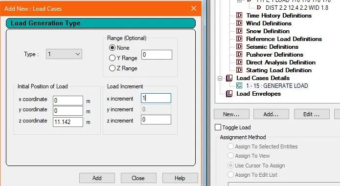
We now Run Analysis.
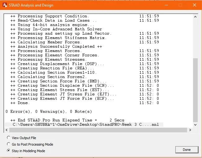
The analysis has Zero Errors and Zero Warnings
Results:
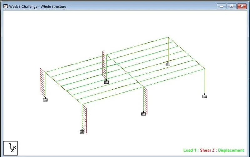
We will now study the analysis in Post - Processing Mode
- Deflection in Fx
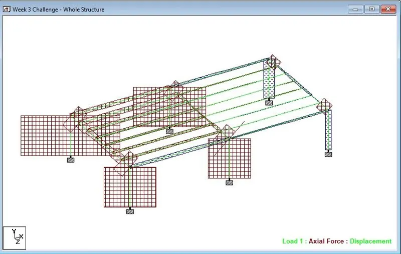
- Deflection in Fy
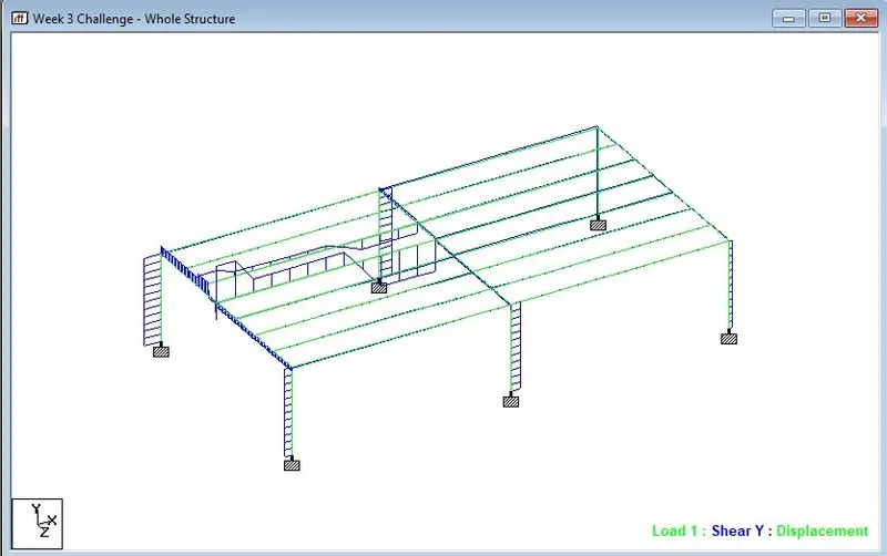
- Deflection in Fz
In conclusion, other forms of railway loading can be generated on a given model in the same way after defining the vehicle loads as per IRS.