Challenge 4
Aim:- Prepare a longitudinal model of I-girder and analyze for all the loads with the following specifications
Given Data:-
- Grillage model of 4 I-girders with span length of 27.0m.
- Having supports at 0.700m from both ends.
- Having the following geometrical properties
-
End Section: Area = 1.218m2
Iy = 0.32541m4
Iz = 0.05129m4
-
Mid Section: Area = 0.87702m2
Iy = 0.27835m4
Iz = 0.02622m4
Procedure:-
Step (1) - Creating Grid Modeling in STAAD.Pro
Creating node (0,0,0) -> Selecting Node using node cursor -> Copy it in X direction using Translation repeat option
Connect both the node -> Geometry -> Add beam
- According to the suitable size create a Girl model
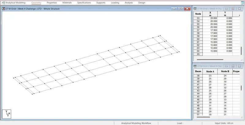
Step (2):- Assigning Support
Specification -> Support -> Create -> Fix but -> Release ( MX, MY, MZ ) -> Add -> Select support 2 -> Select node -> Assign to selected nodes -> Assign
Specification -> Support -> Create -> Fix but -> Release ( FX, MX, MY, MZ ) -> Add -> Select support 3 -> Select node -> Assign to selected nodes -> Assign
Specification -> Support -> Create -> Fix but -> Release ( FZ, MX, MY, MZ ) -> Add -> Select support 4 -> Select node -> Assign to selected nodes -> Assign
Specification -> Support -> Create -> Fix but -> Release ( FX, FZ, MX, MY, MZ ) -> Add -> Select support 5 -> Select node -> Assign to selected nodes -> Assign
- Select node according to suitable support and assign to it
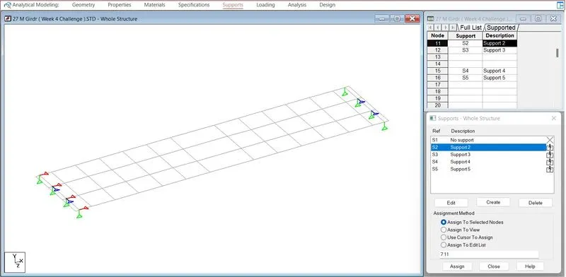
Step (3):- Assign Property to Model
Specification -> Property -> Define -> General -> Insert the value Cross-section dimension of beam -> Add -> Select the property -> Select the beam -> Assign to selected beam -> Assign
- Repeat the same step according to the suitable dimension of different types of beam
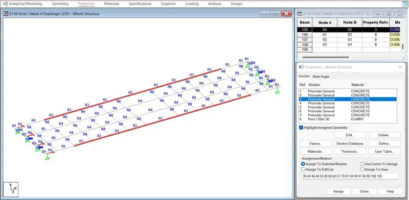
Step (4):- Applying Loading on Model
I. Vehicle Definition
Loading -> Load & Definition -> Definitions -> Vehicle Definition -> Add
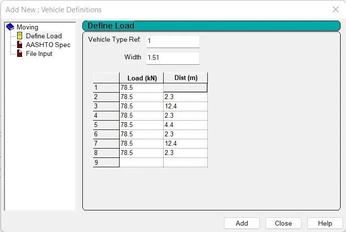
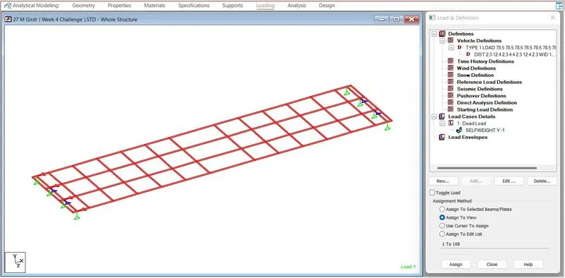
II. Dead Load.
Loading -> Load & Defination -> Load Case Detail -> Tital ( Dead Load ) -> Add -> Select Dead Load -> Add -> Self Weight Factor -1 -> Add -> Select Selfweight - 1 -> Assign to view -> Assign.
III. SIDL
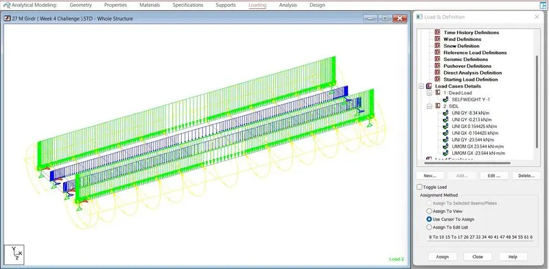
Loading -> Load & Definition -> Load Case Detail -> Title ( SIDL ) -> Add -> Select SIDL -> Add -> Member Load -> Uniform Force -> W1 -8.34 Direction GY-> Add -> Select Load -> Select Suitable beam Beam -> Assign to selected beam -> Assign
- Repeat the same procedure for different beams according to suitable force.
IV. Load Generation
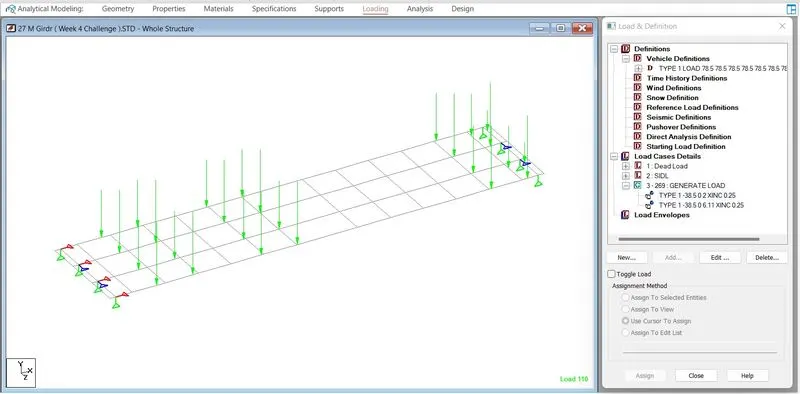
Loading -> Load & Definition -> Load Case Detail -> Add -> Load Genaration -> No of load to be generated -> Add -> Generted Load -> Position of coordinate -> Add
Step (5):- Analysis And Result
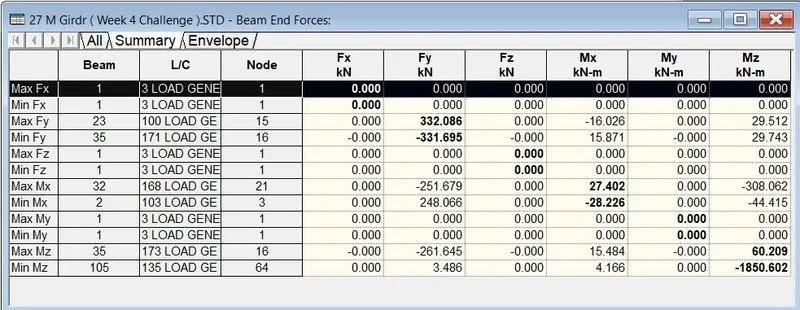
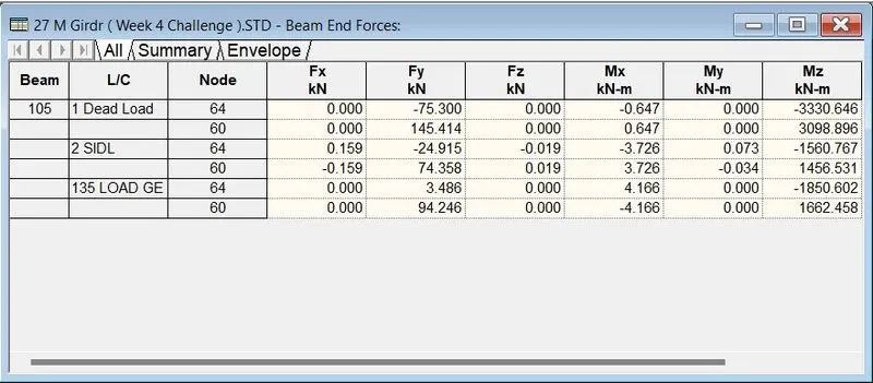
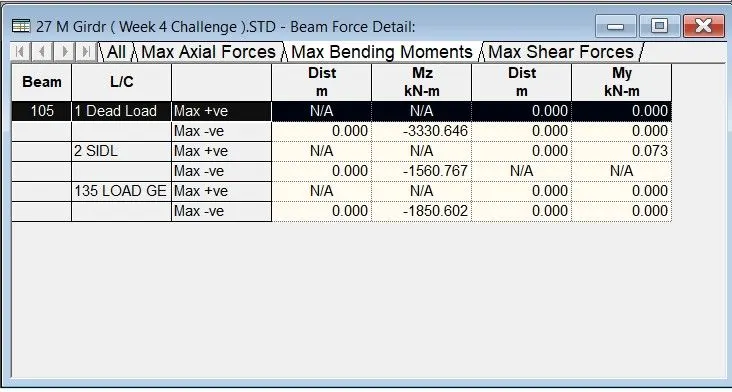
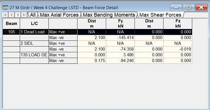
Analysis And Design -> Analysis Commands -> Run Analysis -> Go to post prossing mode -> Done
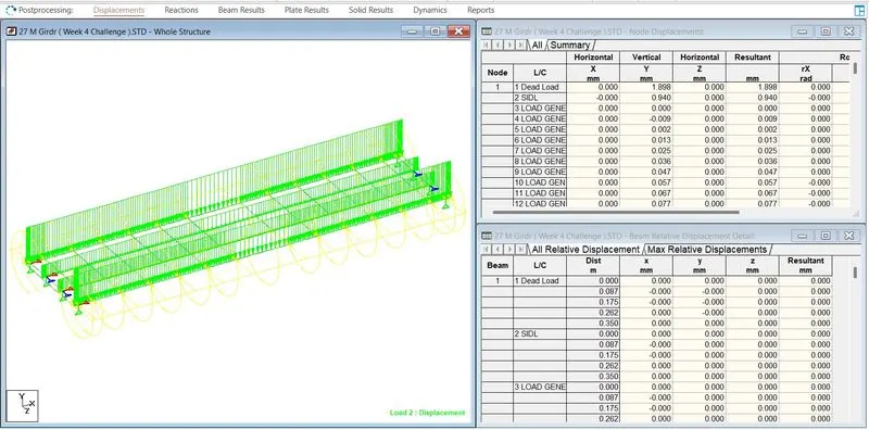
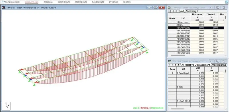
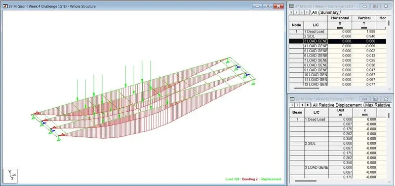
- Maximum MZ of Vehicle load