Week 3 Challenge
Aim
- To determine how the hydrology and geotechnical studies (preliminary and detail studies, zone of influence) are used in fixing span as per IRC standards and type of bridge with the clause applicable for the same.
- To determine Scour Depth at the Pier and Abutment location.
- To determine the measures taken to avoid scour at bridge for shallow foundation and to draw the section of measures on the downstream and the upstream side.
- To determine the effect of uplift on foundation and to calculate the uplift on U-trough. Also to determine the measures taken to avoid uplift.
Procedure
Hydrological studies:
Hydrological studies are done for the following reasons:
- To calculate design discharge which helps in deciding total length of the bridge, depth of the foundation and river training works if required.
- Calculation of discharge is done by calculating the catchment area and then, discharge formulas can be used to calculate the velocity and discharge of the river.
As per IRC:5-2015 Clause 106
Design discharge for which the waterway of the bridge to be provided, shall be based on maximum flood discharge of return period of 100 years. The design discharge shall be the maximum estimated discharge determined by consideration of the following:
From the rainfall and other characteristics of the catchment:
- By the use of an empirical formula, applicable to that region, provided that empirical formula can predict the maximum discharge for given return period.
- By a recognized method, provided it is possible to evaluate, for the region concerned, the various factors employed in that method.
- By the area velocity method with the help of hydraulic characteristics of the channel.
- By unit hydrograph method.
As per IRC:5-2015 Clause 106.5
After determining the design discharge, one can find out the linear water way for the bridge.
For natural channels in alluvial beds but with well-defined banks and for all natural channels in beds with rigid in-erodible boundaries, the linear waterway shall be distance between banks at HFL, at which the designed maximum discharge determined can be passed.
For natural channels in alluvial beds and having undefined banks, the linear waterway shall be determined from the design discharge using some accepted rational condition is
W = C√ (Q)
W = regime width in meters (equal to effective linear waterway under regime condition)
Q = the maximum design discharge in m3/sec;
C = a constant usually taken as 4.8 for regime channels but it may vary from 4.5 to 6.3 according to local conditions.
Based on linear waterway, length of the bridge is fixed.
Types of bridges based on the span:
- Solid slab = span upto 10m
- Precast portal/ Arch = Span 10 to 30m
- Voided slab = Span 10 to 40m
- Ribbed slab = Span 10 to 50m
- Precast beams = Span 20 to 60m
- Composite I girder = Span 20 to 80m
- Box girder = Span 20 to 300m
- Stressed ribbon = Span 30 to 100m
- Bespoke arch = Span 50 to 300m
- Extradosed = Span 100 to 300m
- Cable-stayed = Span 100 to 350m
As per IRC:5-2015 Clause 106.6
If the waterway is restricted, it will cause afflux at the bridge and design HFL will accordingly be raised.
The afflux shall be calculated by using any suitable method based on conservation of energy or momentum. In absence of any rigorous method, the afflux may be calculated by using Molesworth formula as given below :
h = (V2/17.88 + 0.015) x ((A/a)2 – 1)
Where:
h = afflux (in meters)
V = average velocity of the water in the river prior to constriction (in m/sec)
A = unobstructed sectional area of the river at proposed site (in sq. m)
a = constricted area of the river at proposed site (in sq. m)
Geotechnical studies: Geotechnical Investigation helps us to understand the properties of the soil in the bridge location. It helps us to determine soil properties and ground water conditions & Ground water table, Selection of foundation type and depth, suitability of the site for the proposed project. Seismic activity in the area, to know the depth of types of soil below the foundation, to know SBC, also to improve the site condition.
Scouring & Methods to avoid scouring: Scouring is defined as the lowering or loss of top bed soil (erosion) around the bridge piers, abutments, spurs etc. due to the water flow currents. Scouring is always a potential threat to bridge stability eventually it can lead to foundation failure.
As per IRC:5-2015 Clause 106.9.3
The following theoretical method may be adopted when dealing with the natural channels flowing over scour able beds for the estimation of mean depth of scour ‘dsm’ in meters. Mean depth of scour is given as,
Where,
Db = The discharge in m^3/s per meter width. The value of “Db” shall be the maximum of the following:
Ksf = the silt factor
The maximum scour depth below the highest flood level (HFL), which is to be considered for the purpose of design of foundations, protection works, and river training works.
Maximum depth of scour for foundation design for flood without seismic condition
- For piers = 2dsm
- For abutments = 1.27dsm with approach retained or LWL (whichever is deeper)
= 2.00 dsm with scour all around
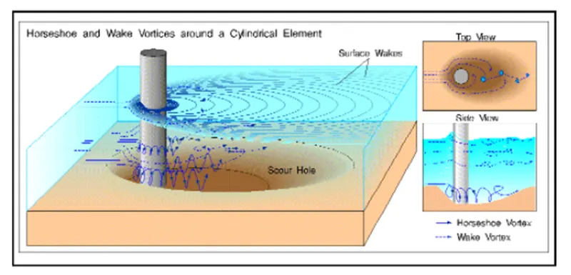
Fig: Scouring (https://www.aboutcivil.org/local-scour-clear-water-scouring.html)
Fig: Figure showing upstream and downstream aprons and cutoff walls for super passage cum cart-track crossing (SP-CTC box type)
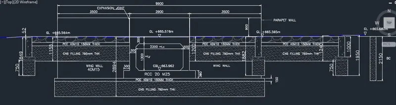
For the design of protection works in the floor for raft or open foundation, below values of maximum scour depth can be adopted.
- In a reach which is straight= 1.27dsm
- In a bend 1.5dsm or based on concentration of flow.
- The length of the apron on upstream may be 0.7 times the length of the apron on downstream.
Methods to prevent scouring:
- Protection works
- Providing flexible and rigid aprons
- Cutoff walls/ curtain walls
- Providing adequate depth of foundations
Problem: Determine the scour depth at the pier and abutment location having silt factor =3
Design discharge = 1000 cumecs
Linear waterway = 128 m
Data provided:
Silt factor = 3
Linear waterway = 128m
Design discharge Q= 1000 m^3/s
For the margin of safety, Q x 1.3 = 1000*1.3 =1300 m3/s (As per IRC:5-2015)
Mean scour depth
dsm = 1.34 * ((((1300/128)^2)/3)^(1/3)
dsm = 4.36m
Maximum depth of scour for piers = 2 dsm = 2*4.36 = 8.72m
Maximum depth of scour for abutment = 1.27 dsm = 1.27*4.36 = 5.537m
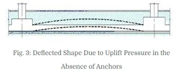
Uplift: Uplift pressure, which is also known as hydrostatic uplift, is an upward pressure applied to a structure that has the potential to raise it relative to its surroundings. It is the condition of greater pore water pressure than the overburden pressure of the structure. The structure must be designed properly to provide greater resistance against uplift forces in order to prevent risks due to water pressure. So, the uplift pressure must be taken into consideration during design stage since rehabilitation and maintenance of foundation cannot be carried out easily in the future.
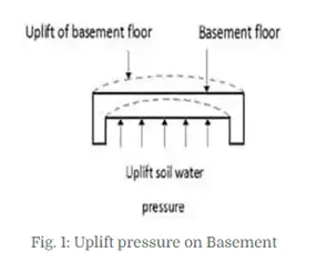
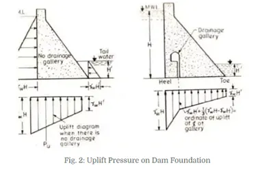
Strategies for Prevention of Uplift Pressure
Dewatering procedure may help to control the water away from construction site, but it cannot keep the dewatering the whole life span of the construction as it is not an economical move. There are number of methods by which the influence of uplift pressure is avoided.
1. Toeing in the Foundation into the surrounding ground
When a substructure is built inside an open excavation or temporary cofferdam, the base slab or raft foundation can be extended outside perimeter to increase resistance to uplift.
The weight of backfill material on the tied-in foundation increase the weight of the structure against uplift pressure. This method is not feasible where a diaphragm or secant pile wall is used as a permanent retaining structure.
2. Increase Self-weight of the Structure
The self-weight of the building can be increased by increasing the size of structural members. Sometime, the dead weight of the low-rise podium in a high-rise complex is increased by incorporating a rooftop garden with a thick soil fill.
3. Ground Anchors
Pre-stressed anchors can be used as a temporary measure to counteract uplift forces. Permanent application of ground anchors is limited by concerns about their long-term performance with respect to corrosion.
4. Piling Method
The piling method is the most effective method to resist Uplift pressure. Various types of piles are available to be used for countering uplift pressure based on soil condition and their necessity on site.
Problem: Calculate the uplift in U trough of below section with height 3, 4 and 5 meters. With water level on top of ramp wall level.
Solution: Unit weight of water = 10kN/m^3
Uplift pressure = Ý w H
- Uplift pressure in u trough for 3m height of water
H = 3+0.68+0.1 = 3.78m
P = 10*3.78 = 37.8 kN/m^2
- Uplift pressure in u trough for 4m height of water
H = 4+0.68+0.1 = 4.78m
P = 10*4.78 = 47.8 kN/m^2
- Uplift pressure in u trough for 5m height of water
H = 5+0.68+0.1 = 5.78m
P = 10*5.78 = 57.8 kN/m^2