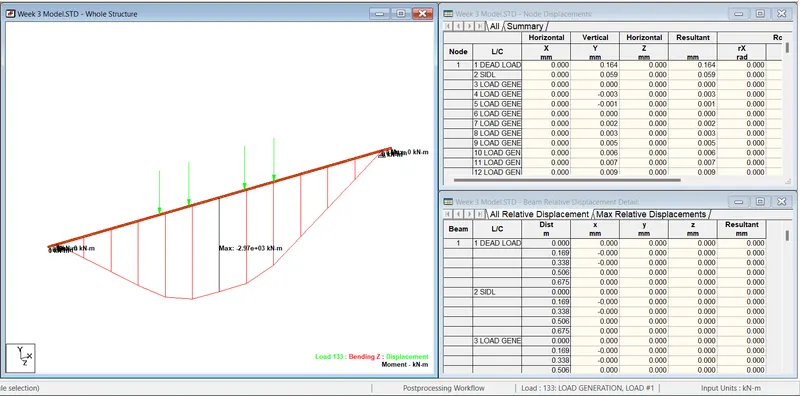
Challenge 3
Aim:-
Que (1):- What are the sectional properties we need upfront for designing a metro viaduct? What is the supporting software for identifying the sectional properties and designing them?
Answer:-
Following are the sectional properties that are considered upfront for designing a metro viaduct.
- Area of section
- Perimeter of section
- bounding box
- Moment of inertia
- Centroid
- Sectional Modulus
- Radius of gyration
Supporting software
- Autocad
- Shapebuilder
- STAAD.Pro
- Midas
- CSI bridge
Que (2):- Explain the detailed steps involved in how elements are created in STAAD Pro and how are the inputs for sectional properties assigned?
Answer:-
- Following are the steps involved in how beam elements are created in STAAD Pro
- First, open the STAAD.pro Fill in all model information and then click on create to start modeling.
- Create a single node using STD-nodes (0,0,0).
- Then select that node using node cursor and copy it in direction (i.e. X, Y, Z) using translation repeat according to which type of model we have to make.
- After that click on the geometry ribbon in that select add beam option by using this option connect the two nodes hence beam is created.
- Next step is to assign the support for that to go to the specification ribbon there select the support and then assign.
- After assigning support next step is to assign the property for that click on the properties ribbon define the section (i.e Rectangular, Circle, etc) select the beam, and assign it to it.
- Then applying the loading on structure for that click on loading tab create the loads (i.e Dead, SIDL, Live, etc) by using load case detail the assign it on the model.
- The Last step is to analyze and design of structure for that click on the analysis and design ribbon then define the command and click on run analysis for analysis of the structure.
- This all step is used to creating the element
- Following are the steps involved in how plate elements are created in STAAD Pro
- First, open the STAAD.pro Fill in all model information and then click on create to start modeling.
- Create a single node using STD-nodes (0,0,0).
- Then select that node using node cursor and copy it in direction (i.e. X, Y, Z) using translation repeat according to which type of model we have to make.
- After that click on the geometry ribbon in that select add plate option by using this option connect all four nodes hence plate is created.
- Next step is to assign the property for that click on the properties ribbon define the Thickness, put the suitable thickness then select the plate and assign it to it.
- Then applying the loading on structure for that click on loading tab create the loads (i.e Dead, SIDL, Live, etc) by using load case detail the assign it on the model.
- The Last step is to analyze and design of structure for that click on the analysis and design ribbon then define the command and click on run analysis for analysis of the structure.
- This all step is used to create the element
Que (3):- What are SLS combinations used for live loads, concerning impact factors and how the moments for the section are derived?
Answer:-
According to code provision SLS combination used for live loads is taken from the below table
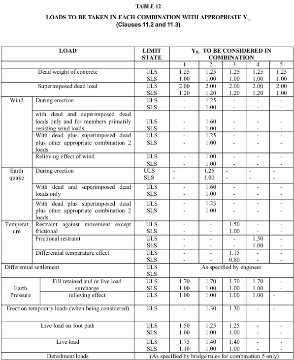
Calculating the impact factor and moment section by using this formula:
I (Impact) = 1 + [0.15 + (8/(6 + L))]
= 1 + [0.15 + (8/6+25.6)) x (90/116)]
= 1.313
Moment (M) = (4183.35 + 1.2 x 1797.228 + 1.1 x 2969.161 x 1.313) kN-m
= 10628.58 kN-m
Que (4):- What is prestressing in girders? What are the advantages of Prestressed girders in a metro project?
Answer:-
the concrete is poured around the already-tensioned cables and allowed to harden and hold the cables in place. When the concrete is solid and cured, the ends of the tensioned cables are cut and the tension is released into the beam or slab. Prestressing Techniques. Precast prestressed girders are a type of concrete girder that facilitates the rapid construction of a bridge using girders fabricated off-site and then transported and erected into place at the job site.
Advantages of Prestressed girders in a metro project
- A properly engineered prestressed-concrete beam can span longer distances than a reinforced-concrete beam and it is thinner, lighter in weight, and uses less concrete without cracking or breaking.
- The inherent compressive strength of concrete is used to its fullest.
- The special alloy steels used to form the prestressing tendons are used to their fullest.
- Tension cracks are eliminated, reducing the risk of the steel component corroding.
- Shear stresses are reduced.
- For any given span and loading condition a reduction in weight can be achieved by using a component with a smaller cross-section
- A composite member can be formed by joining individual Precast concrete units together.
Que (5):- Explain about prestressing losses? What are different type of prestressing losses and mention the significance of the prestressing losses?
Answer:-
Prestressing is the process of introducing compressive stress to the concrete to counteract the tensile stresses resulting from an applied load. The gradual reduction of this introduced compressive stress in a prestressed member due to various reasons is called losses of prestress.
Following are the clauses given in the IRS CBC which include the type of prestressing losses.
- 16.8.2.2 Loss of Prestress due to Relaxation of Steel.
- 16.8.2.3 Loss of prestress due to Elastic Deformation of the Concrete.
- 16.8.2.4 Loss of prestress due to Shrinkage of the Concrete.
- 16.8.2.5 Loss of Prestress due to Creep of the Concrete.
- 16.8.2.6 Loss of Prestress during Anchorage.
- 16.8.2.7 Loss of Prestress due to Steam Curing.
- 16.8.3 Loss of Prestress due to Friction.
Losses in prestress are caused because of friction produced in the process of tensioning. It is developed between the tendons and the concrete surface. There exist two major types of losses in prestress which are Immediate (Short term) and Time-Dependent Losses (Long term).
Que (6):- How a girder is being prestressed while fabrication? Explain the components/materials used during the prestressing.
Answer:-
- In the fabrication stage below, we can see the highly tensioned steel “strands” or wire cables, which are very long horizontal lines at top and bottom and diagonally across the middle, all extending from one end of the future beam to the other. The vertical steel elements, curved and shaped at the top and bottom, are the traditional “rebars” or reinforcing steel, creating the steel cage that gives shape and added strength to the finished beam.
- The steel strands are stretched to create an extremely high state of tension or stress and anchored in the large bulkhead at the end of the beam. When stretched and stressed, the strands will become 20 to 30 inches longer.
- The long prestressing and fabricating bed allows more than one beam to be made at the same time, For economy and efficiency, the steel strands are pulled and tensioned through two beams at once.
- After all the steel is in place, metal forms are positioned on both sides of the steel cages (below) for the concrete mix. The metal forms will create the traditional I-beam shape of the finished prestressed concrete beam.
- When the forms are removed, the finished concrete beam emerges, displaying its I-beam shape below. It is now “prestressed pretensioned,” because the concrete has formed and hardened around the tensioned steel strands. At that point, the strands are cut at the ends of the beams. The stretched steel strand wants to return to its original, shorter length, but the concrete hardened around it prevents it from returning back. The force in the strand is induced to the concrete to put the concrete beam in in a state of high compression as the stress is incorporated into the whole beam.
- This beam is now ready to be hauled to a bridge construction site.
Following are components/materials used during the prestressing.
- Steel.
- Tendons.
- Wire strand or cable.
- Bars.
- Concrete.
- Shuttering or formwork
Que (7):- How are stresses in the girder calculated with the resultant prestressing losses?
Answer:-
Prestressing Losses
Elastic Shortening
`Delta fy = mfc`
Where,
`Delta fy`= Drop in prestress
m = Modular Ratio
`fc` = Stress in concrete
Friction Loss
`Px = Poe^(mux.kx)`
Where Px = Prestressing force at a distance x from jacking end.
Po = Prestressing force at jacking end.
k = coefficient called wobble correction factor
μ = Coefficient for friction in curve
α = Cumulative angle in radian through which the tangent to the cable profile turned between any
two point under consideration.
Anchorage Slip
`(P/A) = (EsDelta)/L`
`Delta`= Slip of anchorage
L = Length of cable
A = Cross sectional Area of Cable
Es = Modulus of Elasticity of Steel
P = Prestressing Force in Concrete
| Anchorage system | Anchorage slip (Δ) |
| Freyssinet | 4 mm |
| 12-5 mm ϕ strands | 6 mm |
| 12-8 mm ϕ strands | 8 mm |
| Magnet | 1 mm |
Creep and Shrinkage Losses
Creep Loss:`Delta fp = Epepsiloncr,u l t`
Shrinkage Loss: `Deltafp = Epepsilonsh`
Where,
`Deltafp`= Loss in Prestress
Ep = Modulus of Prestressing Steel
εcr,ult = Ultimate Creep Strain
εsh = Ultimate Shrinkage Strain`epsilon`
Prestressing:
- No. of strands used (n) = 72
- Prestressing Force Applied (P) = (0.765fpu.As.n.(1-loss))/1000)kN
= (1422.9 x 140 x 72 x 82.5%)/1000
= 11832.8kN
- Section Modulus (Z) = 1/Y
- For checking Stress at Bottom
Ybot = 0.594m
Z = (0.74035/0.594) cu m
= 1.2464 cu m
- For checking Stress at Bottom
- CG of Section of CG of tendons (e) = (o.594 - 0.140)m
e = 0.454m - Stress at Bottom = `P/A + (P times e)/2 +M/Z`
= `11832.8/2.1735 + (11832.8 times 0.494)/1.2464 - 10628.58/1.2464`
= (5444.12 + 4689.83 - 8527.42) kN/sq m
= 1.607 N/sq mm
Que (8):- Explain the step wise procedure of transverse analysis of open web structure of U girders in STAAD pro along with how the vehicle parameters and loadings are fed in the STAAD software.
Answer:-
Following are the procedure
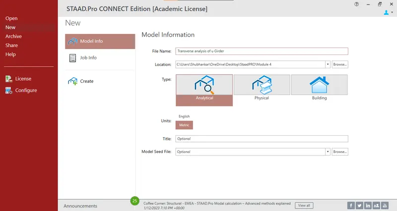
Step (1):- Opening of Software
- Opening The software and filling the model imformation
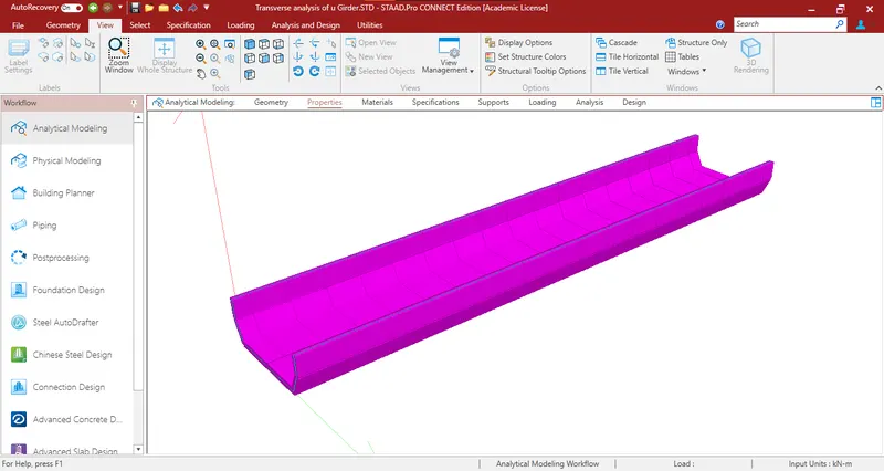
Step (2):- Creating U Girder model
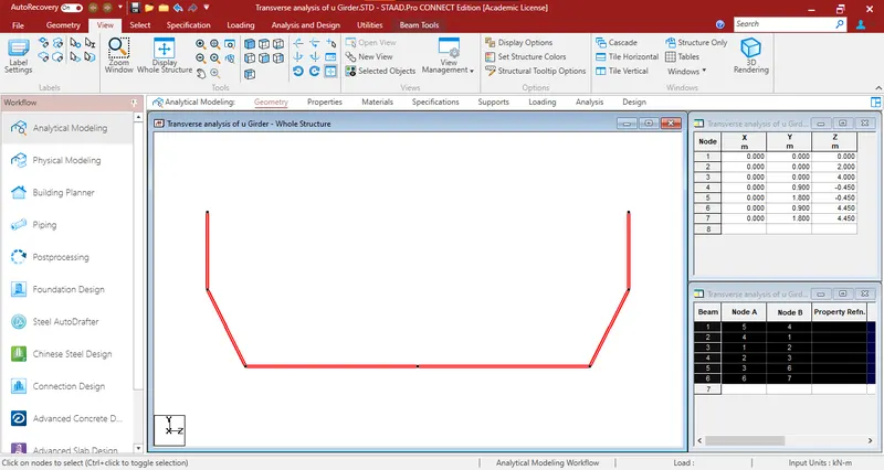
- Arranging the node in shape of U Grider
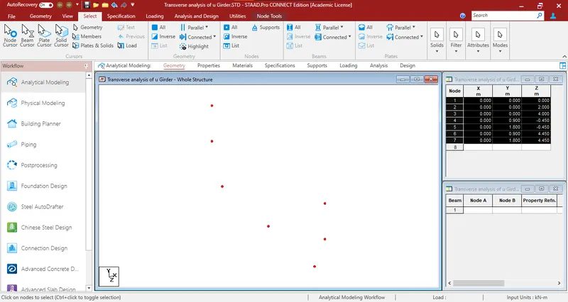
- Connecting node by using add beam option
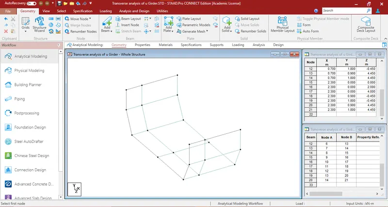
- Copy node in X direction using the translational repeat option and assigning the plate using add plate option
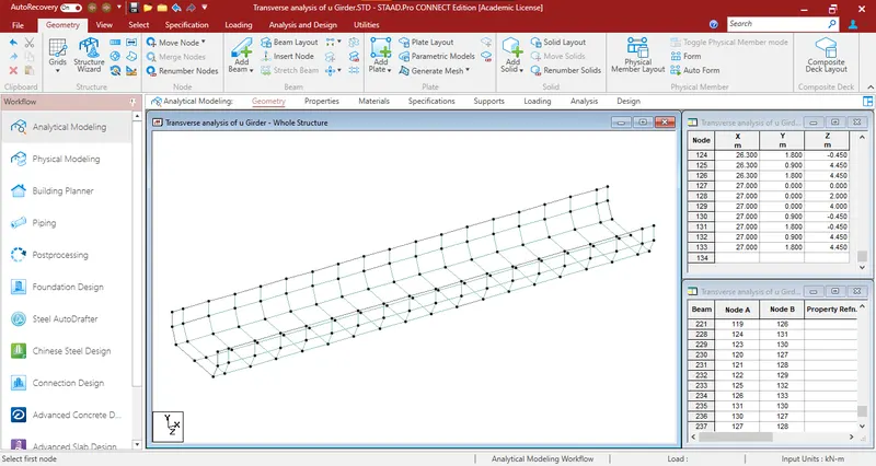
- Making Full U Girder model using translation repeat option.
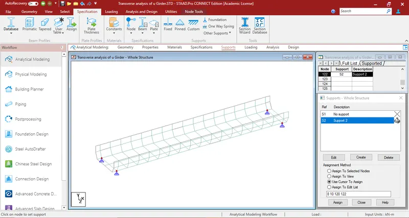
Step (3):- Assinging the support
Specification -> Pinned suport -> Add -> select support 2 then select node -> Assign
Step (4):- Assgning the property to all plate
Property -> Thickness -> Add -> Select Plate -> assign
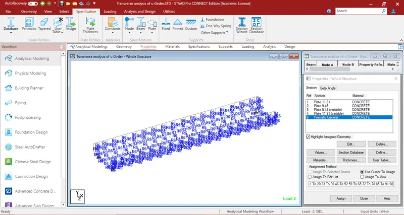
3D Model
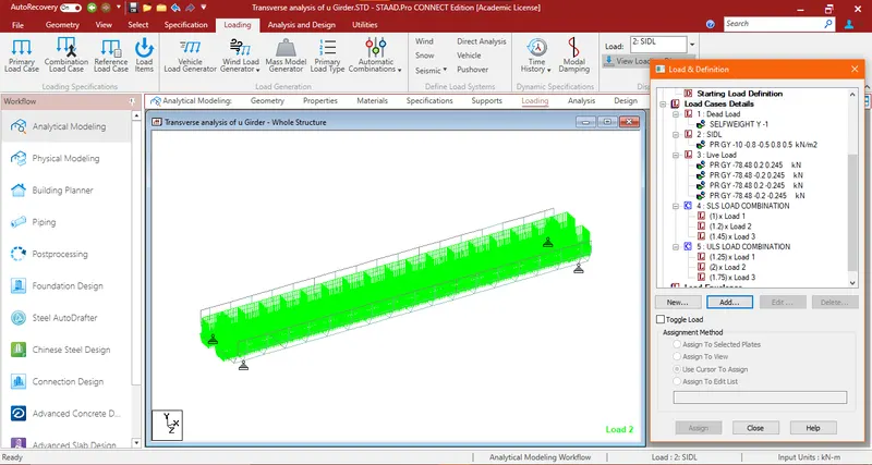
Step (5):- Applying Loading on Model
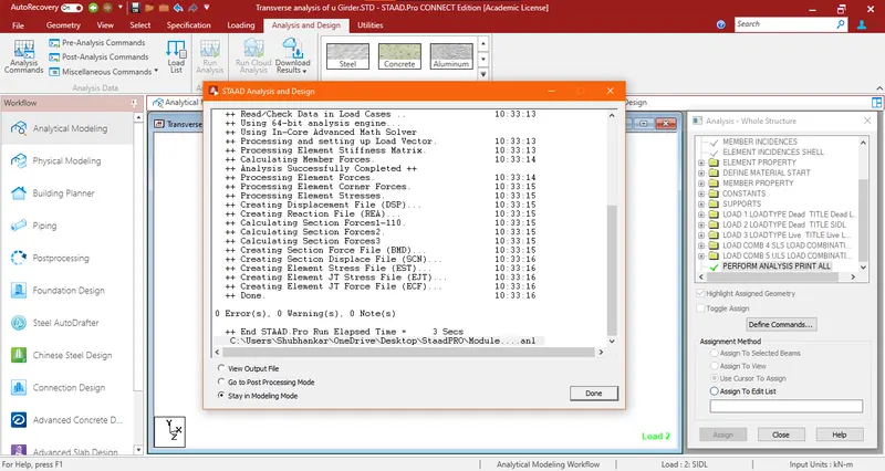
Step (6):- Analyis of model
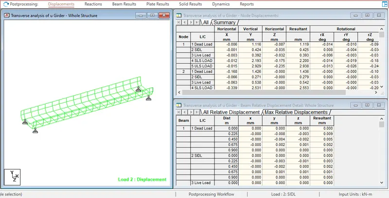
Step (7):- Result Extraction
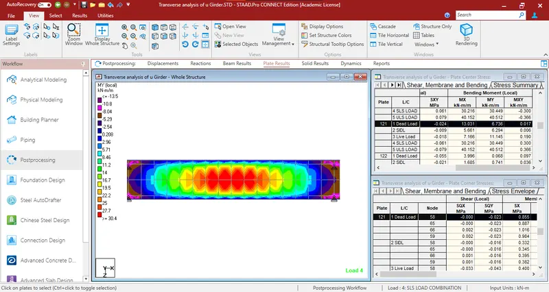
- Maximum MY in SLS combination
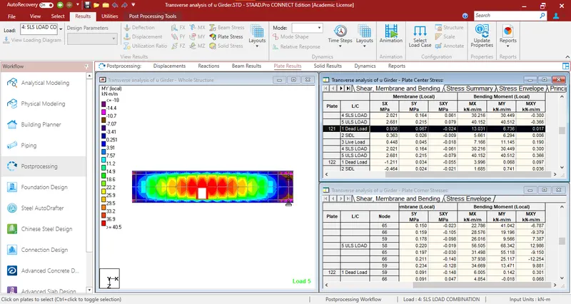
Plate no 121 has maximum bending moment
- Maximum MY in ULS combination
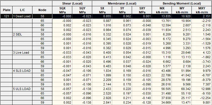
- Summary of forces
Que (9) :- How is the longitudinal analysis of open web structure of U girder performed, final design bending moments and axial stresses are extracted? Explain the software procedure for extracting the same.
Answer:-
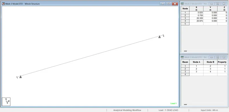
Step (1):- Creating Model & assigning Fix support.
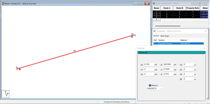
Step (2):- Assigning property
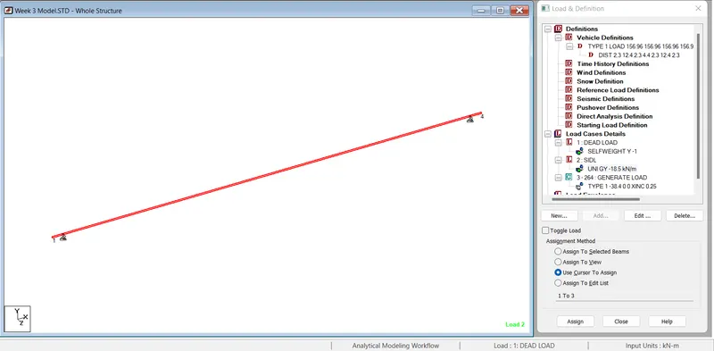
Step (3):- Applying Loads on model
Step (4):- Analyis and Result extraction of model