To Study about the Induction Motor Characteristics and its Parameters.
AIM : To Study about the Induction Motor Characteristics and its Parameters.
OBJECTIVES :
-
Discuss about the equivalent circuit network of induction motor MATLAB model.
-
3 phase, 50 Hz induction motor, represented by equivalent circuit constants X1 = X2 = 0.1 ohm and R1 = R2 = 0.2 ohm is operated at half of rated voltage and frequency. Calculate the ratio of starting torque at half voltage & frequency to rated values.
-
Make a comparison of square wave inverter output voltage with sine modulated one.
STUDY - 1 :
Equivalent Circuit of Induction Motor :
- Given below the equivalent circuit of an Induction Motor with stator & Rotor circuits separated. The frequency of currents inboth circuits are different.
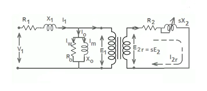
- Suppose the frequency of the rotor circuit is f2 & frequency of the stator circuit is f1 & let the sli``p value will be s.
f2 = s*f1 - this means the frequency of the rotor circuit varies by a factor of s with respect to f .
- In the above figure, V1 is applied voltage to the stator E1 is the induced emf. R1 & X1 is the stator resistance respectively. l1 is the current flowing through the stator circuit, lo is the no load current which splits into lm which is magnetizing component & lw is the core loss current. Xo is the pure inductive reactor and Ro is the non-inductive resistor.
- E2 is induced emf in the rotor circuit, R2 & X2 is the rotor resistance and reactance respectively.
- Given below is the equivalent circuit with reference to the stator. This is made possible by making the frequencies of stator and rotor circuits equal.
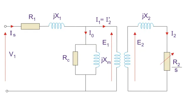
- An induction motor consists of a stationary component called the stator and a rotary component called the rotor. The stator consists of 3 coiled windings supplied with 3 phase AC power which is wound around the stacks if thin, high permeable laminations in a cast iron or steel frame changing the frequency of 3 phase power supply (i.e. sinusoidal supply voltage and current phasors) will generate the rotating magnetic field.
- This induces an emf and therefore the current in the rotor when the magnetic field interacts with the rotor via electromagnetic induction. But now the rotor is current carrying conductor in the rotating magnetic field, it will experience electromagnetic force producing a torque via the motor effect.
- The induced emf in the rotor as a result of electromagnetic induction is also referred as ‘back emf’ because it acts in the opposite direction to the direction of the 3 phase voltage across the coil windings in the stator.
- The magnetizing inductance, lm is required at the air gap because across it is the boundary between stator and the rotor, the stator will produce the rotary magnetic field & it needs to cross the air gap to interact with the rotor to excite it to produce the torque. So the magnetizing inductance, lm is needed to cross the air gap.
- Xm, X1, X2 all represent inductance values, resistance is a form of opposition that the electronic components exhibit to the passage of current through them due to their capacitance or inductance properties.
Operation :
- The speed of the rotating magnetic field is also known as the synchronous speed and it is dependent upon the frequency of 3 phase power supply & no. of poles of the inductance motor. So the frequency of the 3 phase power supply is proportional to the synchronous speed and also the motor speed.
- p = No. of Poles.
- f = Frequency of 3 –Phase power supply.
This can be also expressed as,
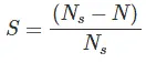
- Ns is Synchronous Speed
- N is Rotor Speed
- The torque that is produced by the rotor of the induction motor can be expressed mathematically as so :
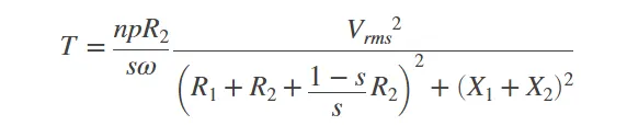
- n = No. of Poles.
- X1 = Stator Inductance.
- X2 = Rotor Inductance.
- V = Root Mean Square Voltage.
Exact Equivalent Circuit :
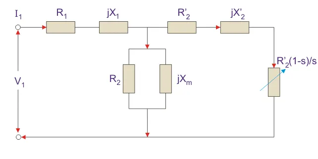
Here,
The rotor winding resistance is referred to the stator winding.
X2’ is the rotor winding inductance.
R'2 (1 –s) / s is the resistance which shows the power which is converted to mechanical power. The power dissipated in the resistor is the useful power output or shaft power.
Now,
Zeq = (R1 + R’2 (1-s) / s) + j (X1 + X’2 )
ls = V1 / Zeq
Putting the value of Zeq we get,
ls = V1 / [R1 + R’2 (1 –s) /s + j (X1 +X‘2)]
ls = |ls| = V1 / [(R1 + R’2 (1 –s)/s)^2 + j (X1 + X’2 )^2]
P = V1 ls cos2 = (V1^2)(R’2 (1-s)/s) / [R1 + R’2 (1-s)/s)^2 + (X1 + X’2 )^2]
Torque equation is given by,
T = P/ Ws
T = (V1^2) (R’2 /s)/Ws [R1 + R’2 (1-s)/s)^2 + (X1 + X’2 )^2]
Simplified Induction Motor Simulink Block :
- The Simplified Induction Motor block represents the electrical and torque characteristics of an induction motor powered by an ideal AC supply. This block is available in the Simscape library.
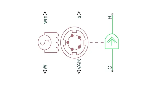
- The block does not model the starting mechanism for a single-phase induction motor.
- When you parameterize the block by motor ratings, the block derives the equivalent circuit model parameters by assuming that the effect of the magnetizing inductance L is negligible, and the magnetizing inductance is not included in the simulated component.
The output of this model are :
- Real Power
- Mechanical Speed
- Imaginary Power
- Motor Slip
Induction Motor Simulink Block :
- The Induction Motor block implements a three-phase induction motor. The block uses the three-phase input voltages to regulate the individual phase currents, allowing control of the motor torque or speed.
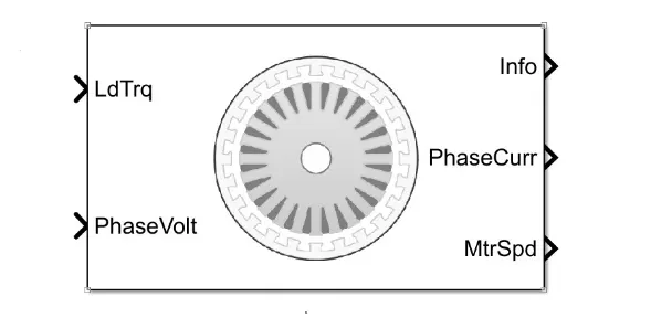
- By default, the block sets the Simulation Type parameter to Continous use a continuous sample time during the simulation. If you want to generate code for fixed-step double- and single-precision targets, considering setting the parameter to Discrete. Then specify a Sample Time, Ts parameter.
The Output of this block are :
- Phase Current
- Motor Torque
- Motor Speed
STUDY - 2 :
Given :
No. of Phases = 3
Rated Frequency = 50 Hz
Stator Inductance (X1) = 0.1 Ohms
Rotor Inductance (X2) = 0.1 Ohms
Stator Resistance (R1) = 0.2 Ohms
Rotor Resistance (R2) = 0.2 Ohms
We need to find the starting torque at the half rated voltage and frequency to the same at the rated voltage & frequency –
The given data with respect to the equation is –
T = (3 / ωms ) * [( (V^2) * (R2/s)) / ((R1+(R2/s))^2 + (X1+X2)^2)]
Since we are only required to find out the starting torque hence, we can eliminate the slip term ‘S’. this is because at the starting torque, the motor speed is ‘0’ so the synchronous speed terms will cancel each other out that means the slip will take a maximum value of 1.
The equation for slip is -
slip, s = ( ωms - ωm ) / ωms
So we can rewrite the torque equation omitting the slip term ‘s’, since it’s equal to 1.
The starting torque is given by the equation –
T = (3 / ωms ) * [( (V^2) * R2) / ((R1+R2)^2 + (X1+X2)^2)]
Now we can use this equation to find out the starting torque at the half rated and full rated condition.
Synchronous Speed :
The formula to find out synchronous speed is –
ωms = (120 * f) / P
Where,
f = Frequency.
p = No. of Poles.
Let the half rated synchronous speed = ωms1
Let the rated synchronous speed = ωms2
Half rated frequency = Rated Frequency / 2 = 50/2 = 25 Hz.
Half rated voltage = Rated voltage / 2 = V/2.
ωms1 = (120*25) / P
ωms1 = 3000 / P
Rated Frequency = 50 Hz.
ωms2 = (120*50) / P
ωms2 = 6000 / P
Since, we know that the rated synchronous speed is double the half rated synchronous speed, we can express the latter in terms of the former.
ωms1 = ωms2 / 2
NOTE : Since R1,R2,X1,X2 are the constant values it will never be changed once the motor is manufactured in the factory but the value of the voltage and the poles can be changed according to the needs of the power of the motor.
Formula :
Starting torque for half Rated Voltage & Frequency
Ts1 = (3 / ωms1) * [((V/2)^2 * R2) / ((R1+R2)^2 + (X1+X2)^2)]
Ts1 = (3 / (ωms2 /2)) * [((V/2)^2 * R2) / ((R1+R2)^2 + (X1+X2)^2)]
Ts1 = ((3*2) / ωms2 ) * [((V^2/4) * 0.2) / ((0.2+0.2)^2 + (0.1+0.1)^2)]
Ts1 = ( 6 / ωms2 ) * [((V^2/4) * 0.2) / (0.04+0.08+0.04+0.01+0.02+0.01)]
Ts1 = ( 6 / ωms2 ) * (( (V^2/4) * 0.2) / 0.2)
Ts1 = ( 3 / ωms2 ) * (V^2/2)
Ts1 = ( 1.5 / ωms2 ) * (V^2)
Starting torque for Rated Voltage & Frequency
Ts2 = (3 / ωms2) * [((V^2) * R2) / ((R1+R2)^2 + (X1+X2)^2)]
Ts2 = ( 3 / ωms2 ) * [((V^2) * 0.2) / (0.04+0.08+0.04+0.01+0.02+0.01)]
Ts2 = ( 3 / ωms2 ) * (((V^2) * 0.2) / 0.2)
Ts2 = ( 3 / ωms2 ) * (V^2)
Comparison of starting torque at both conditions :
The starting torque at the half rated condition is :
Ts1 = ( 1.5 / ωms2 ) * (V^2)
The starting torque at the full rated condition is :
Ts2 = ( 3 / ωms2 ) * (V^2)
So the ratio of –
Ts1 / Ts2 = (( 1.5 / ωms2 ) * (V^2)) / (( 3 / ωms2 ) * (V^2))
Ts1 / Ts2 = (( 1.5 / ωms2 ) * (V^2)) / (( 3 / ωms2 ) * (V^2))
Ts1 / Ts2 = 1.5 / 3
Ts1 / Ts2 = 1/2
Therefore, the ratio of the starting torque at the half rated condition to the full rated condition is 1/2 or 0.5.
STUDY - 3 :
INVERTER :
- The inverter converts battery DC electricity to AC electricity. DC signal looks like a unidirectional straight line and AC signal looks like waves of ocean. DC wave cannot travel long so all our home electricity is supplied in AC manner.
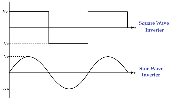
- The majority of household electrical appliances use an Alternating Current (AC) electricity. On the other hand, a battery stores Direct Current (DC) electricity. The main purpose of an inverter is to convert the DC electricity into AC electricity.
- But when it comes to the basis of its circuits, an inverter converts DC current to either Square wave AC current or Sine wave AC current. The Sine wave inverter output is very similar to the AC current. In comparison with the Square wave output, the Sine wave output is purer; that’s also the reason why the term Pure Sine wave inverter exists.
- One more important thing that need to know is many household devices get heated up if you’ll use Square wave inverters. This is the reason why Square wave inverters are banned in some European countries. Other than that, we outlined a comparison chart between Sine wave inverters and Square wave inverters below to help you differentiate them better.
PWM INVERTER :
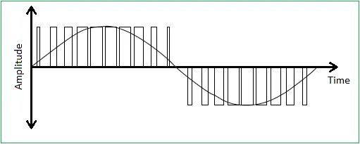
- Pulse Width Modulated inverters(PWM inverter) replaced the older versions of inverters and has a wide range of applications. Practically these are used in the power electronics circuits.
- The inverters based on the PWM technology possess MOSFETs in the switching stage of the output. Most of the inverters available nowadays possess this PWM technology and are capable of producing ac voltage for varying magnitudes and frequencies.
- There are multiple protection and control circuits in these types of inverters. The implementation of PWM technology in the inverters makes it suitable and ideal for the distinct loads connected.
-
These are capable of maintaining the output voltages as the rated voltages depending on the country irrespective of the type of load connected. This can be achieved by changing the switching frequency width at the oscillator.
Comparison of Square Wave and Sine Wave Inverters :
|
List of Features |
Square Wave Inverter |
Sine Wave Inverter |
|
Describe |
|
|
|
Output Waveform |
|
|
|
Uses |
|
|
|
Supported Appliances |
|
|
|
Overall Safety Level |
|
|
|
Noise Interference |
|
|
|
Cost |
|
|
CONCLUSION :
- Successfully discussed about the equivalent circuit network of induction motor.
- Completed Calculation of the ration of starting torque at half voltage & frequency to rated values.
- Compared different types of inverter circuits and its output voltage.
REFERENCES :
https://jpilms.gnomio.com/mod/book/view.php?id=468&chapterid=272
https://www.electrical4u.com/equivalent-circuit-for-an-induction-motor/