Study the Induction Motor Torque-Speed Characteristics and Calculate the Equilibrium Point & Steady State Point of the Drive Using Matlab.
AIM : Study the Induction Motor Torque-Speed Characteristics and Calculate the Equilibrium Point & Steady State Point of the Drive Using Matlab.
OBJECTIVES :
-
To explain about how Induction Motor Operation is similar to Clutch.
-
To Calculate the Starting time of a drive with the given parameters.
-
Obtain the equillibrium points and determine the stability for a drive.
- Make a MATLAB script file which will plot speed-torque characteristics for frequency control method.
STUDY - 1 :
The Induction Motor Operation is Compared to a Mechanical Clutch's Operation by the Following : -
Mechanical Clutch Operation :
- A clutch is a mechanical device which engages and disengages power transmission especially from Driving shaft to Driven shaft. In the simplest application, clutches connect and disconnect two rotating shafts .
- In these devices, one shaft is typically attached to an engine or other power unit while the other shaft (the driven member) provides output power for work.
- The clutch connects the two shafts so they may be locked together but they are spinning at different speeds because of the slip.
- This is beacause of the power losses happening by not properly engaging while transmitting the power (i.e) speed and Torque from driving shaft to the driven shaft.
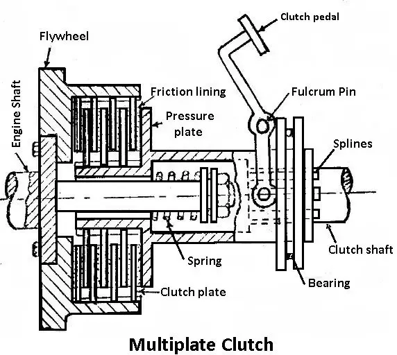
- From the above figure we can say that the speed and torque is transfered from the driving shaft to the driven shaft.
- In this process the speed will not be the same in both the shafts beacause of the slip losses
W2 = W1 (1 - S)
W1 = Speed of the driver shaft
W2 = speed of the driven shaft
S - Slip
Induction Motor Operation :
- Induction motor has two main parts, Stator and Rotor. Stator is basically 3 coil winding and 3-phase AC power input is given to it. The Winding passes through slots of the stator, which are made by thin and highly permiable steel laminations inside a steel or cast-iron frame. When the 3-phase current passes through windings and it produces a Rotating magentic field.
- This Rotating Magnetic field is causes the rotor to turn. 3 coils are connected 120 degree apart. A wire carrying current produces magnetic field arounded. Rotational Speed of the magnetic field is known as Synchronous Speed(Ns).
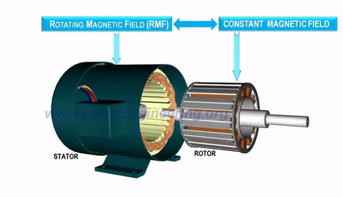
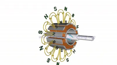
- Assume Conductor is placed in centre of 3 windings. Magnetic field will vary, emf will be induced in the loop. An EMF will produce current in the loop. Electro Magnetic force is produced on the loop and the loop was start to rotate. The same phenomenon occurs in the Induction motor as well.
- Instead of loop squirrel cage rotor is used in Induction motor. 3-phase AC power input is pasing through the stator produces magnetic field and current will be induced in the bars of the squirrel cage. So the rotor starts to rotate.
- When the rotor and Magnetic field both are rotating in a same speed, magentic field will never cut the loop. Thus, there will not be any induced EMF and Current. This translates zero force of the rotor part and the rotor will gradually slow down. As it slows down, magnetic field will cut the rotor loop, so induced EMF and current rise again and the rotor will then speed up.
- Rotor will rotates in a specific speed which is slightly less than the synchronous speed(Ns). Difference between the Synchronous Speed(Ns) and Rotor Speed(Nr) is known as Slip.
Slip = (Ns-Nr)/Ns
Ns - Synchronous Speed,
Nr - Rotor or Motor Speed,
Sometimes, Ns-Nr is called Slip speed
Obviously Rotor or Motor speed is
Nr = Ns(1-s).....eqn(a)
- It may be kept in mind revolving flux is rotating synchronously, relative to the stator (i.e., stationary space) but at slip speed relative to the motor.
- Induction Motor do not require permanent magnets, Brushes, Commutator rings, Position sensors like other machine mechanical parts. Induction motor are also Self Started. The main advantage is Induction motor Speed can control easily by controlling input power of Frequency.
Electromagnetic Clutch :
- A Clutch is a mechanical device which engage and disengage power transmission especially from driving shaft to driven shaft. In simplest application Clutch connect and disconnect two rotating shafts.
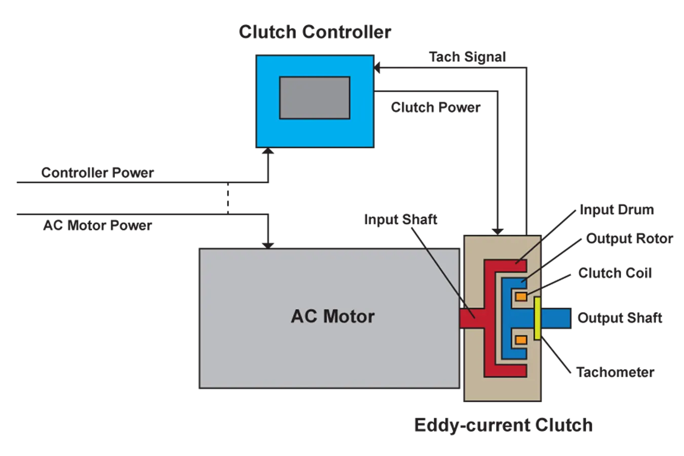
- A Electromagnetic clutch is a clutch (a mechanism for transmitting rotation) that is engaged and disengaged by an electromagnetic actuator.
- In this type of clutch flywheel consists of winding. The current supplied to the winding from battery or dynamo.
Eddy Current clutch :
- AC Induction motor is coupled to an eddy current clutch. Eddy Current Clutch, also known generally as Magnetic drive, eddy current clutch or magnetic clutch, is a electro mechanical variable speed drive that uses a constatnt speed motor as the input.
- The eddy current clutch is installed between the motor and driven equipment.
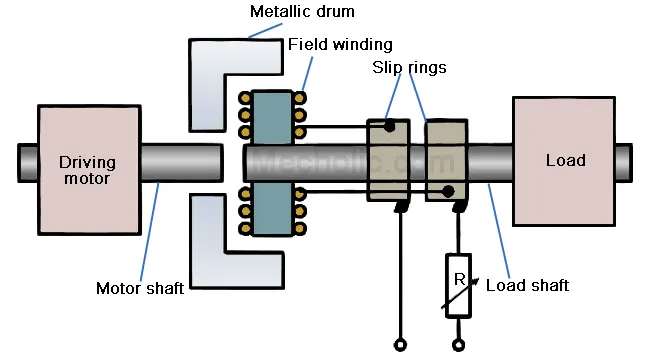
- Eddy current clutches are driven at a constant speed by an AC induction motor. The AC motor interacts with an electromagnetic clutch that controls both the torque and speed that is transferred to the driven load.
- The clutch itself is installed between the constant speed AC motor and the equipment being driven. The clutch controller governs the amount of power that the clutch receives (which is separate from the AC motor power).
- Included as part of the magnetic rotor is a direct-current (DC) excitation coil that is regulated by the clutch controller. The magnetic rotor combined with the DC excitation coil serves as the electromagnetic coupling that varies the output speed and torque of the clutch’s output rotor and shaft.
- A rotating drum (sometimes called a ring) is coupled directly to the Drive shaft (shaft of the motor) and rotates at a constant speed. A Rotor (contains Electromagnetic coils) coupled directly to the Driven Shaft. The Speed of the clutch can be controlled by varying the amount of direct current applied to the rotor. Since the Output Speed(ω2) is determine by the amount of slip between the rotor and drum.
Slip = (ω1-ω2)/ω1
ω1 - Drive Shaft Speed(Input Speed)
ω2 - Driven Shaft Speed (Output Speed)
Therefore, Output speed is
ω2 = ω1(1-S) .... eqn(b)
From Eqn (a) and Eqn (b), we know that Clutch and Induction motor has similarities in both operation.
- When the direct current is applied to the rotor, the spinning electromagnetic eddy currents induce into the metal drum. The induce eddy currents form magnetic poles inside the drum.
- The magnetic fields of the rotor and drum attracted to eachother, and clutch turns in the same direction of the motor.
- The main advanatage of eddy current clutch is that no mechanical connection between the rotor and drum. Since there is no mechanical connection, there is no friction to produce excessive heat and there is no wear as is the case with mechanical clutches.
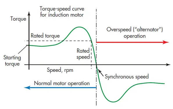
- The Speed of the clutch can be controlled by varying the amount of direct current applied to the rotor. Since the Output Speed is determined by the amount of slip between the rotor and drum.When load is added, the slip will become greater and causing a decrease in speed.
- This can be compensated by increasing the amount of direct current applied to the motor. In Stable region the clutch is fully enganged to transfer 100% efficient as there is no related slip and in Unstable region Clutch is disengaged.
- Therefore the operation of the induction motor and the clutch are similar to each other.
STUDY - 2 :
To calculate the starting time of a drive with the following parameters : -
Given Data :
J=10 kg-m2,
T = 15 + (0.5 .ωm)
Tl=5+ (0.6 .ωm)
To Find :
A starting time of the drive
Solution :
The basic fundamental equation of motor load system can be represented as
T-Tl = d/dt(J.ωm)
By differentiate right side we gate
T-Tl = d/dt(J.ωm) = J(dωm/dt) + ωm(dJ/dt)
where, T = Torque of motor
Tl = Load Torque
ωm = Motor Speed
J = Moment of inertia of motor
t = Starting time
From the above equation
consider the drive with constant inertia dJ/dt=0. Therefore the equations becomes,
T-Tl = J(dωm/dt) ..........(1)
Now substituting the value of T and Tl in equation (1)
(15+(0.5)*ωm) - (5+(0.6)*ωm) = 10*(dωm/dt)
10-0.1ωm = 10*(dωm/dt)
10*(1-0.1/10.ωm) = 10*(dωm/dt)
(1-0.01.ωm) = (dωm/dt)
By rearranging this equation we get,
dt = dωm/1-0.01.ωm .........(2)
Now integrating equation (2) on both sides
`int`dt = `int(domegam)/(1-0.01.omegam)`
t = `int(domegam)/(1-0.01.omegam)`.........(3)
we consider v=1-0.01 .ωm
differentiating v on both sides,
dv/dωm = -0.01
Integrate this equation
t = `int(domegam)/v.(dv)/(domegam)`
t = `int(1/v)dv`
t = -100ln(v)
t = -100ln(1-0.01ωm) ........(4)
For steady state , T-Tl = 0
substitute T-Tl = 0 in fundamental equation
(15+(0.5)*ωm) - (5+(0.6)*ωm) = 0
10-0.1ωm = 0
-0.1ωm = -10
ωm = 10/0.1=100
ωm = 100 rad/sec
The speed of the drive is 100 rad/sec.
transient operation over time is considered to be over 95% change in speed taken place. Therefore final speed ωm2 will be 95% of speed ωm
ωm2 = 100*95/100 = 95rad/sec
Applying in equation (4)
t = -100ln(1-0.01*95)
t = -100ln(0.05)
t = -100(-2.9957)
t = 299.57sec
The starting time of the drive is 299.57 sec.
(a) Calculating Equilibrium Points :-
Matlab Code :
clear all
close all
clc
%calculating the equilibrium points
w = linspace(0,150);
Tm = 15+(0.5*(w));
Tl = 5+(0.6*(w));
%plotting the omega and motor torque that represented as red colour
plot(w,Tm,'linewidth', 1.4,'color','r')
title('Determining Equilibrium Points')
xlabel('Speed (rad/s)')
ylabel('Torque (N-m)')
hold on
%plotting the omega and load torque that represented as blue colour
plot(w,Tl,'linewidth', 1.4,'color','b')
legend('Motor Torque','Load torque')
grid on
- Here w is considered as linspace value of 0 to 150. Whereas the motor torque value and load torque value is equated as by given in the question. Now the value of w is equated in that motor torque load and load torque equation up to 150 value.
- Therefore w will obtain 150 points that point are considered as equilibrium points. By plotting the motor torque value of w with the load torque value with speed w an intersection point is obtained that value is w = 100 rad/sec.
Output Plot :
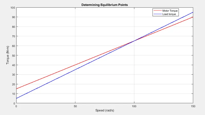
- The output value is w = 100rad/sec as we derived by the equation.
(b) Calculating the starting time of the drive :-
Matlab Code :
clear all
close all
clc
t_p = [0 299.57];
ic = [0 0];
% using ode45 solver we obtain w for each time span and initial condition
[t,w] = ode45(@omega,t_p,ic);
plot(t,w,'linewidth', 1.4)
title('Determining Starting Time')
xlabel('Time (sec)')
ylabel('Speed (rad/s)')
grid on
%function program
%Here we comsider w_dot = 1-0.01*(w) and equate in main program for
%differentiation as solver ode 45
function [w_dot] = omega(t,w)
w_dot = 1-0.01*(w);
end
- In this program, we calculate the constant speed of the motor through derivation of w(dw/dt). We are using time of 0 to 299.57sec because we derived the equation above and obtained this time value whereas initial condition is referred in the program.
- The Function program is called here in main program for ode 45 solver to differentiate at each time. The function is named as omega(t,w) and the equation is w_dot = 1-0.01*(w).
- These equation is differentiated in that solver up to the 299.57sec. Therefore the constant speed of the drive is obtained in time t= 299.57sec as we discussed in study-2 equations.
Output Plot :
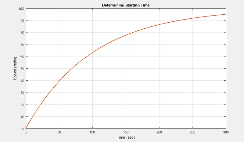
- The starting time of the drive is 299.57sec.
STUDY - 3 :
To calculate the stability and equilibrium points of the drive with the following load torque and motor torque equation : -
Given Data :
Tm=(1+2ωm)
Tl= 3 √ωm
To Find :
The stability and equilibrium points of the drive
Solution :
Condition for stability :
`(dTl)/(domegam)-(dTm)/(domegam)>0`
If dωm>0 , Tl>Tm
dωm<0 , Tm>Tl
where,
Tm = Torque of motor
Tl = Load Torque
ωm = Speed of motor in rpm
At steady-state stability
Tm = Tl
equating both the values,
1+2ωm = 3 √ωm
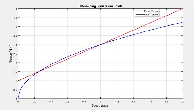
By solving this equation we obtain two equilibrium points ωm = 0.25 and 1.
Calculating Equilibrium Points :-
Matlab Code :
%calculating equilibrium points
clear all
close all
clc
%Here Tm and Tl values are taken from study-3
w = linspace(0,2);
Tm = 1+(2*w);
Tl = 3*sqrt(w);
%plotting the omega and motor torque that represented as red colour
plot(w,Tm,'linewidth',1.4,'color','r')
title('Determining Equilibrium Points')
xlabel('Speed (rad/s)')
ylabel('Torque (N-m)')
hold on
%plotting the omega and load torque that represented as blue colour
plot(w,Tl,'linewidth',1.4,'color','b')
legend('Motor Torque','Load Torque')
grid on
- This program is executed as same as the study-2 for calculating the equilibrium point of the drive.
Output Plot :
-
The two equilibrium points are obtained in this graph that are initiated as two dots and the values of ωm = 0.25 and 1 .
-
Now we differentiate the load torque and motor torque interms of motor speed, therefore we get
Tl = (3)/(2).√ωm
Tm = 2
-
We substitute the value of motor speed ωm = 0.25 and 1 in this equation Tl and Tm to obtain stability points.
- sub ωm = 0.25 in that equation
Tl = (3)/(2).√0.25
Tl = 3
Hence Tl = 3 and Tm = 2 are obtained in motor speed of ωm = 0.25 , according to the conditions of stability the value of load torque is greater than value of the motor torque that system is considered as a stable condition. Whereas by applying the speed of ωm = 0.25 in the differential equations of load torque and motor torque. So the value ωm = 0.25 is the stability of a drive.
- sub ωm = 1 in that equation
Tl = (3)/(2).√(1)
Tl = 1.5
Hence Tl = 1.5 and Tm = 2 are obtained in the motor speed of ωm = 1 , according to the conditions of stability the value of load torque is lesser than value of the motor torque that system is considered as an unstable condition. In this case, the load torque is lesser than the motor torque by substituting the speed of ωm = 1 in the differential equations of load torque and motor torque. Therefore, the system will be unstable. So the value ωm = 1 is not stability point of the drive.
STUDY - 4 :
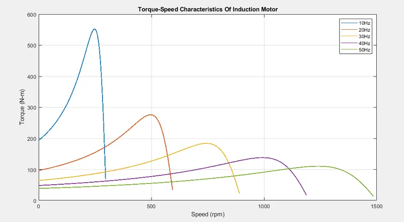
- The frequency control method is one of the few ways in which the speed of an inducton motor can be controlled in its operation. Varying the frequency will vary the speed of the rotating magnetic field i.e. the synchronous speed and this will in turn vary the speed of the rotor i.e. the motor speed.
- Different frequencies of operation will have different torque-speed characteristics because each frequency will have a different synchronous speed. Each synchronous speed will correspond to a different motor speed and hence a different slip between itself and the motor speed. This in turn will result in different torques.
- In the MATLAB script, we have used the same data wich is normally have for any motors. These are as follows :
-
Rated Freqency - 50Hz
-
Number of Phases - 3
-
Stator Inductance, X1 = 0.680 Ohms
-
Rotor Inductance, X2 = 0.672 Ohms
-
Stator Resistance, R1 = 0.095 Ohms
-
Stator Resistance, R2 = 0.23 Ohms
Torque - Speed Characteristics for Frequency Control method : -
Matlab Code :
clear all
close all
clc
% Inputs
% Voltage per phase
V = 230/sqrt(3);
% Number of phase
ph = 3;
% Number of poles
P = 4;
% Stator resistance and inductance
R1 = 0.095;
X1 = 0.680;
% Rotor resistance and inductance
R2 = 0.23;
X2 = 0.672;
% Magnetizing inductance
Xm = 18.7;
% Calculate stator equivalent equations
Zeq = 1i*Xm*(R1+1i*X1)/(R1+1i*(X1+Xm));
Veq = abs(V*1i*Xm/(R1+1i*(X1+Xm)));
% Frequencies
Fz = linspace(10,50,5);
% Loop
for i=1:5
 % Motor Speed calculation
 w = (4*3.14*Fz(i))/P;
 Ns = (120*Fz(i))/P;
 for n=1:100
 % Slip
 s(n) = n/100;
 % Motor speed in rpm
 W(n) = Ns*(1-s(n));
 % Current in rotor
 I2 = abs(Veq/(Zeq+1i*X2+R2/s(n)));
 % Torque calculation
 T(n) = ph*I2^2*R2/(s(n)*w);
 end

 % To display maximum speed of motor at different frequencies
 Curve=['The maximum speed of motor at ', num2str(Fz(i)),'Hz'];
 disp(Curve)
 disp(W(1))

 % Plot
 plot(W,T,'linewidth',1.4);
 hold on
 axis ([0 1500 0 600])
 title('Torque-Speed Characteristics Of Induction Motor');
 xlabel('Speed (rpm)');
 ylabel('Torque (N-m)');
end
legend('10Hz', '20Hz', '30Hz', '40Hz', '50Hz');
grid on
- In Input Section of code, we entered the given data in to their respective variables. Since we are varying the frequency, we created an array containing 5 frequency values equally spaced from 10 Hertz to 50 Hertz. Each frequency will correspond to its own speed-torque characteristic.
- Next, we set the numer of phases to 3 since most electric powered devices operate on a 3 phase AC supply. Then, calculated the rated voltage by dividing 230V (the voltage at which electricity is supplied to domestic areas) by the square root of the number of phases. The number of poles of the induction motor is also specified as 4 because there are 2 pole pairs. Finally, the stator and rotor inductance and resistance value are entered.
- After that, we programmed a for loop which will perform the calculations for the torque and the motor speed. This is done by creating a slip array. The slip is the discrepancy between the synchronous and motor speeds. The slip is measured by taking the ratio of the difference between the synchronous and motor speeds to the synchronous speed.
-
Next, the synchronous speed is calculated using the formula: `omega_(ms) = (120 * f)/p`
where,
f - Frequency (Hz)
p - Number of Poles
- A for loop is used for this calculation because we have an array of 5 frequency values and each frequency will correspond to a specific synchronous speed. So the for loop will range from 1 to the length of the frequency array which is 5 which will output 5 synchronous speeds.
- Then, the main torque values are calculated using the original torque formula and in it, the slip term is included. The for loop will range from 1 to the length of the slip array which means we should get an ouput of 100 torque values with each value corresponding to a slip value.
- The slip terms in the torque formula will be replaced with the values from the slip array and the synchronous speeds calculated in the first for loop will also be included. In this for loop, we can also find the motor speed with the slip array and the synchronous speed.
- At last, modifications are made to the plot such as a title, axis labels and a legend key to show that each torque - speed characteristic corresponds to a particular freqency. The 'grid on' command is used to activate the grid of the plot space.
Output Plot :
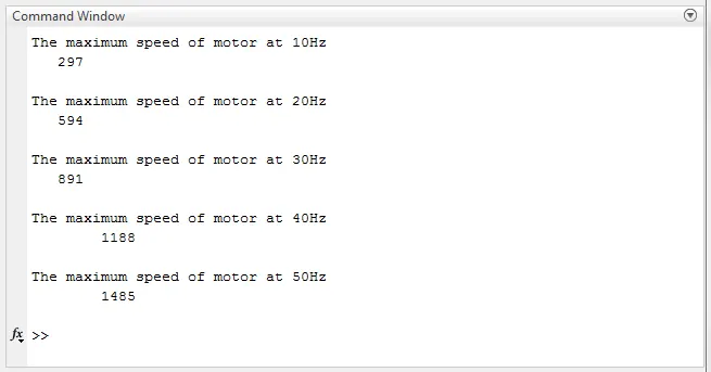
Maximum Speed Attained by Motor at each Frequency :
CONCLUSION :
- The similarities of induction motor and clutch are explained, and the calculation for the starting time of a drive with the given parameters are derived using Matlab.
- The equilibrium points of drive and stability of drive are also obtained by deriving load torque and motor torque equation.
- The stability conditions are also applied to analyze the steady point of drive.
REFERENCES :
https://skill-lync.com/knowledgebase/calculating-starting-time-for-induction-motor-3
https://www.dynamatic.com/dynamatic-technology/how-it-works/