To Study about the Analog & Digital Control Systems.
AIM : To Study about the Analog & Digital Control Systems.
OBJECTIVES :
-
Answer the following -
a.) Compare analog control system with digital one with respect to electric vehicle motor.
b.) Explain callback and over the air update events by automotive companies.
-
Using MATLAB plot bode diagram of chosen transfer function ( second and third order transfer functions to be considered ) in s-domain and z-domain. Comment on the results.
-
Explain the process of Sample and Hold technique in Simulink.
a.) With the help of a “Sample and Hold” block from the library browser.
b.) Without using the default Sample and Hold circuit block from the library browser.
STUDY - 1 :
a.) Comparision of Analog Control System & Digital Control System with respect to Electric Vehicle Motor :
- The word ‘digital’ and ‘analog’ preceding ‘control systems’ do have their literal meaning in electronics.
- Analog control system deals, processes and outputs continuous values between a certain range (theoretically infinite, but practically all actuators are limited to a certain range) while digital makes use of an intermediary binary language for all sorts of computation before it is converted back to analog using digital to analog converters.
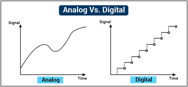
- Since manipulating a continuous signal is much harder, and with advent of powerful computers in recent years, most of control system are digital just because they’re just a whole lot easier to deal with in so many circumstances with the only real addition being ADC and DAC in the process pipeline between the input and output states.
| List of Features | Analog Control System | Digital Control System |
| Signal Type |
|
|
| Wave Type |
|
|
| Technology |
|
|
| Transmission |
|
|
| Flexibility |
|
|
| Bandwidth |
|
|
| Memory |
|
|
| Power requirement |
|
|
| Best suited for |
|
|
| Cost |
|
|
| Example |
|
|
| Impedance |
|
|
| Errors |
|
|
b.) Explanation of Callback and Over The Air Update events by automotive companies :
- Now-a-days EVs & HEVs Call-Back function isn’t much used instead of that ‘Over the Air (OTA)’ is used. Call-Back events used in Automobile industry to call back or recall the past history if they face any problem or difficulty or fault while manufacturing the vehicle.
- Whereas, OTA is a new adopted process where the companies need not to call-back or go or visit the garage or factories and solve the problem without any difficulties. before, Call-back used in previous days. This was done when a vehicle had fault in it.
- Then the car manufacturer will just call back the previous cars so that they can rectify the fault in it and make the required improvements. Vehicle is a dynamic system and it is required to tune the system. there are 2 ways to tune 1) By Tools 2) By Fundamentals. Direct tuning doesn’t help always in such cases with the help of real-time tuning we can tune it accordingly with the help of microprocessors.
- OTA is a new adopted approach where the companies need not to call back, go and visit the garage or factories & rectify the faults and follow required procedures without other cumbersome processes.
- Updating software and firmware using Over-the-Air (OTA) has increased in the handheld devices, industrial, and automotive sectors for the embedded platform with time. Once the product is in the real world, firmware or the software update related to bug fixes, security fixes, or the feature update is required for the betterment of the device and keeping it updated with latest software.
- OTA is a technology to update the software or the firmware remotely.
- In case of a vehicle, the firmware or software is updated wirelessly using a telecommunication device, through a gateway inside the car to the ECU whose presence is increasing in modern vehicle.
- In Automotive industry, the vehicle has become more and more intelligent and smart. Currently, the vehicles are majorly controlled by a software rather than traditional mechanical components.
- OTA solves the problem of reliability of each updated that used to be present earlier, secondly dependency of the service station, carrying the vehicle to the station, the cost of update the software becomes very low, and no much hassle to the customer and well as the service station. Last but not least, the security update on time for every vehicle is important and is done at easeThe approach of the OTA update for the mobile phones and the vehicles are different, the vehicle OTA update is more complex and stringent as compared to the handheld device, improper software update may cause harm to user life too.
- Electronic Control Units (ECUs) has become the major component in the vehicle today, ECU has replaced all mechanical steering components. In general, ECUs are interconnected by one or more networks and share information that enables complex interactions and regulations. For example, In Advanced Driver Assistance Systems (ADAS), the increasing functional capabilities comes with a higher system complexity, which makes software bugs more likely to occur that might have implications for the safety and security of the whole vehicle. With regular software updates and enhancements, one can ensure the systems’ correctness, efficiency, and reliability over the complete lifetime of the vehicle.
- This blogs mainly describe the end-to-end solution that can be deployed to support OTA software updates in the automotive sector. In the previous section, we talked about the OTA and understand that OTA update in the automotive sector has major challenges in terms of security while updating the software over the air. If the attackers get control of the vehicle, one might end up in a hazard situation.
- Engine transmission can be turned on/off
- Passengers or the drivers can be locked inside the car
- Blowing the horn continuously
- Controlling the steering system
- Car braking system
- Speeding the car beyond road regulation.
- Controlling the navigation, audio or infotainment system
- False alarm in the cockpit
Let’s see how the OTA update happens in the vehicle. Overview : The OTA remote update method of the vehicles is fast, cost-effective, and allows updating of the software running on their ECUs over-the-air, and the car users can update the software anywhere without having to go to the service centre or repair shop. Further, OEM can diagnose the car based on the data received through over-the-air from the car.
What does it take to deploy the Uptane ?
- The OEM sets up and maintains
- Director repository
- Image repository
- Time server (optional)
- Images are signed by
- Supplier, or OEM, or Both!
- ECUs shall do either
- Full verification, or
- Partial verification
- May keep using your existing TLS, etc. transport
- If transport / caching compromised, little security risk
Challenges on OTA Update :
- Automotive is more complex architecture with an increasing number of ECU, updating the different type of ECU itself become challenging
- The security of the data over the air is at high risk.
- How to update firmware and software is done using minimal resources like network bandwidth, storage, and compute.
- Is it Possible to update not only the application/ but the core driver /software of the device?
- The rollback mechanism of the software update
- Higher downtime is not accepted while updating the software or firmware.
- The size of the software blocks
- How seamlessly OTA happens with impacting the current system.
STUDY - 2 :
MATLAB plot bode diagram of transfer function in s-domain and z-domain -
Introduction :
This article focuses on the relationship between the Laplace domain (s-domain) and z-domain representations of continuous-time and discrete-time transfer functions. The following two-pole continuous transfer function is used in the interactive demo above and throughout this article :
The continuous-time transfer function has two poles and no zeros. The poles can either be real (and may or may not have the same location) or complex conjugate, where the real parts of the poles are identical and imaginary parts are negative to each other.
The poles of the continuous transfer function can be easily determined :
The discrete counterpart of the transfer function is obtained using the zero-order hold technique :
Using a Laplace to Z transform look-up table :
The following is a generic version :
Where :
Note: The Low-Pass Filter Discretization article explains the discretization process in detail.
The poles of the discrete transfer function correspond to the poles of the continuous time transfer functions such as:
When the zero-order hold technique is used, the natural frequency and damping factor properties of each pole are preserved in the resulting discrete transfer function. This does not hold true for other approximations, such as the Tustin (bilinear) transformation.
The natural frequency and damping ratio of the system poles are defined in the following table (from MatLab documentation), consistent with the simulation.
Note: There are many values of "s" for each "z", e.g.
Thus:
Mapping of continuous-time poles to z-plane
The following table captures the essence of mapping s-plane poles to the z domain.
From Digital Control of Dynamic Systems by Franklin, Powell, and Workman :
S - domain Using MATLAB Bode Plot :
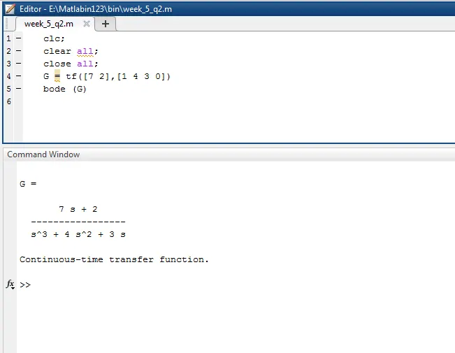
- Here it is the third-order transfer functions to be considered.
- We used the command for the Bode Plot.
Output Bode Plot :
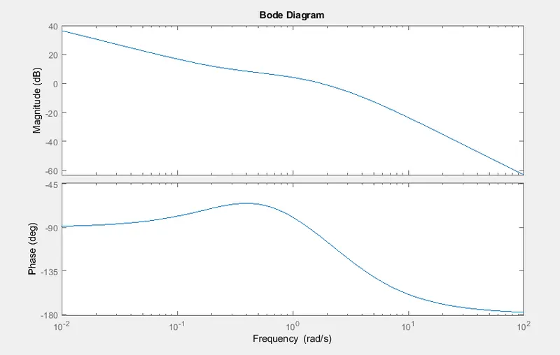
- The above fig. shows a bode plot of the transfer function in the s-domain.
- The Bode Plot can be considered as the visualization of the frequency response of the System as the frequency response of the system contains the knowledge about the variation of the output magnitude and phase with respect to the range of the frequencies of the input signal.
- The bode Magnitude plot measures the system Input/Output ratio in special units called decibels. The Bode phase plot measures the phase shift in degrees (typically, but radians are also used).
Z - domain Using MATLAB Bode Plot :
- Discretize the following continuous-time transfer function :
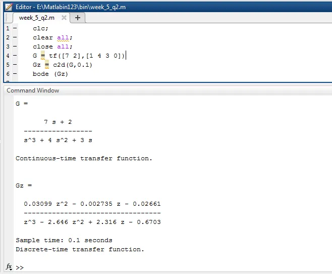
- We can use 'c2d' function in Matlab to convert a continuous transfer function into a discrete transfer function.
-
Here 0.1 is the Ts means sampling time.
Output Bode Plot :
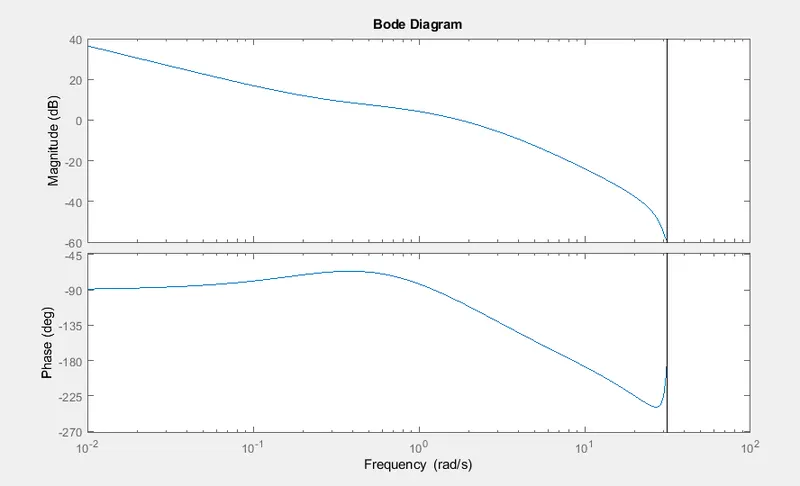
- The above fig. shows a bode plot of the transfer function in the z-domain.
- The Bode Plot can be considered as the visualization of the frequency response of the System as the frequency response of the system contains the knowledge about the variation of the output magnitude and phase with respect to the range of the frequencies of the input signal.
- The bode Magnitude plot measures the system Input/Output ratio in special units called decibels. The Bode phase plot measures the phase shift in degrees (typically, but radians are also used).
STUDY - 3 :
The Process of Sample and Hold Technique in Simulink :
a.) Simulink Module With the help of a 'Sample and Hold' Block :
Sample an input signal when a trigger event occurs and hold the value until the next trigger event using the Sample and Hold block. The trigger event can be one of the following :
-
Rising edge - Negative value or zero to a positive value.
-
Falling edge - Positive value or zero to a negative value.
-
Either edge - Negative value or zero to a positive value and positive value or zero to a negative value.
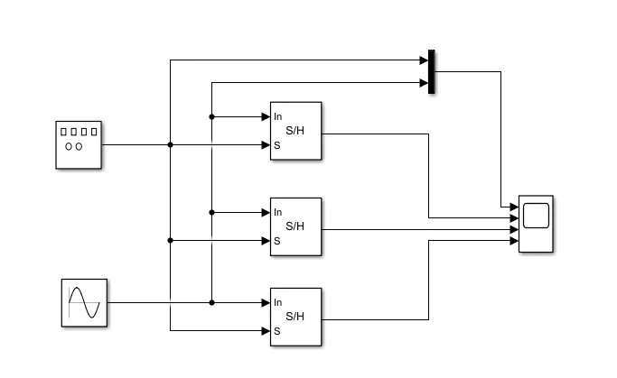
- The model contains three Sample and Hold blocks which accept the three type of trigger events.
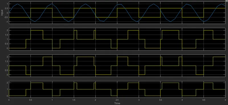
- The input signal is a continuous-time sine wave with an amplitude of 1 and a frequency of 8 rad/sec. The trigger signal is a square wave with an amplitude of 0.5 and a frequency of 1 Hz.
Output Plot of Sample and Hold Block with Sine and Square wave Input :
- When we run the model, the Time Scope block shows the source and trigger signals on the first plot. we can see the three sample and hold outputs on the three remaining plots.
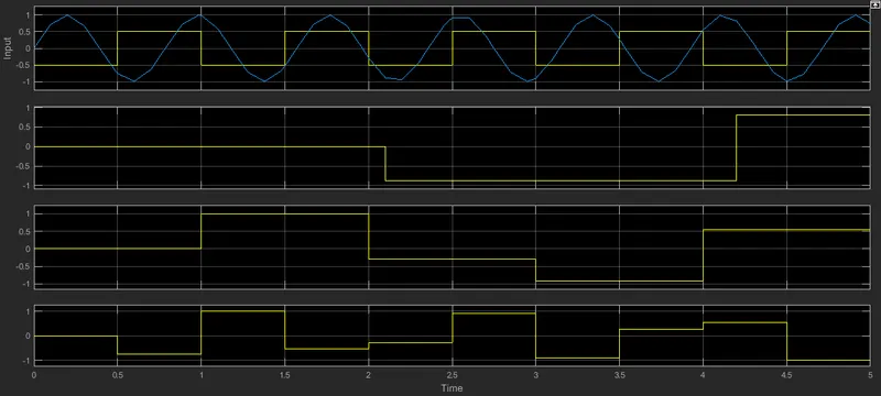
- The Initial condition parameter in all the three Sample and Hold blocks is set to 0.
- Hence, the three output plots start at 0 value. The first trigger is a rising edge that happens at 0.5 seconds.
- The first and third outputs respond to this trigger by dropping to the value of the input sine wave at that point in time. This input value is held until the next respective trigger event occurs.
- The second output plot responds to the first falling edge that occurs at 1 second. At 1 second, the second output plot jumps to 1, which is the value of the sine wave at that point in time.
- This value is held until 2 seconds when the next falling edge event occurs. The output of the second plot then drops down to the value of the sine wave at that point in time. This value is held until the next trigger event occurs.
b.) Simulink Module With the help of a 'Compare To Zero' Block :
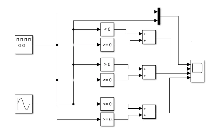
- The model contains Compare To Zero blocks which accept the three type of trigger events.
- The input signal is a continuous-time sine wave with an amplitude of 1 and a frequency of 8 rad/sec. The trigger signal is a square wave with an amplitude of 0.5 and a frequency of 1 Hz.
Output Plot of Compare To Zero Block with Sine and Square wave Input :
CONCLUSION :
-
Compared Analog Control System & Digital Control System with respect to electric vehicle motor and Explained callback and over the air update events by automotive companies.
-
Successfully Plot Bode diagram of transfer function in s-domain and z-domain Using MATLAB.
-
Discussed the process of Sample and Hold technique in Simulink.
REFERENCES :
https://www.tutorialspoint.com/differences-between-digital-and-analog-system
https://www.pathpartnertech.com/understanding-automotive-ota-over-the-air-update/