To Study about the Power Electronics Circuits and Make a Simulink Model for Power Converter Circuit.
AIM : To Study about the Power Electronics Circuits and Make a Simulink Model for Power Converter Circuit.
OBJECTIVES :
-
Why power electronics circuits are efficient ? In practice, which types of losses occur in power electronics circuits ?
-
Using a suitable MATLAB model, show how the duty cycle control signal can be generated for a simple power converter circuit ?
-
Explain the difference between VFD and Vector control drive. Can we use VFD method for induction motor in EV application ?
STUDY - 1 :
POWER ELCTRONICS :
- Power electronics is one of the enabling technologies propelling the shift from conventional gasoline/diesel engine‐powered vehicles to electric, hybrid and fuel cell vehicles.
- It mainly involves the use and control of power semiconductor switches, such as power diodes, insulated gate bipolar transistors (IGBTs) and metal oxide field effect transistor.
- The power electronics circuit controlled the required amount desired in various vehicles and also convert source to the desired output.
- Let for the below example in series HEV the internal combustion engine (ICE) drives a three‐phase permanent magnet synchronous generator, whose output is a three‐phase voltage with variable frequency and variable voltage. This output needs to be rectified to DC.
- The front wheels are driven by an induction motor that needs to be controlled by a voltage source inverter (VSI) or a current source inverter (CSI). An energy storage system is connected to the DC bus, between the generator/rectifier output and the inverter. However, there is a bidirectional DC-DC converter that manages the charge/discharge of the battery, as well as controlling the DC bus voltage.
- In addition, auxiliary components such as headlights, wipers, entertainment systems and heat seats run from the 12 V auxiliary battery.
- Most advanced hybrid vehicles no longer have an alternator which means that the 12 V battery needs to be charged from the high‐voltage (HV) battery. On the other hand, even if an alternator is present when the engine is off the 12 V battery can still be drained quickly without proper charge maintenance. Therefore, it is necessary to have a DC-DC converter to charge the 12 V battery from the HV battery.
POWER ELCTRONIC CONVERTERS :
- Power electronic converters are used everywhere in normal daily routines at home, commercial workplaces or in an industrial environment. Due to the high power handling with higher efficiencies, these converters become an integral part of industrial electric drives, high electric power supplies, electric traction systems and automobile control equipments.
- Power electronic technology deals with processing and controlling the flow of electrical energy in order to supply voltages and currents in a form that optimally suited for end user’s requirements.
- A power electronic converter uses power electronic components such as SCRs, TRIACs, IGBTs, etc. to control and convert the electric power. The main aim of the converter is to produce conditioning power with respect to a certain application.
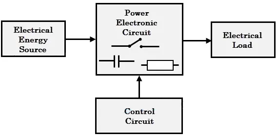
- This block is built with a complex low power electronic circuit that consists of either analog or digital circuit assembly.
- Power electronic converters perform various basic power conversion functions. This converter is a single power conversion stage that can perform any of the functions in AC and DC power conversion systems.
Depending on the type of function performed, power electronic converters are categorized into following types :
- AC to DC ( Rectifier )
- DC to AC ( Inverter )
- DC to DC ( Chopper )
- AC to AC ( Regulator )
Efficiency of Power Electronic Circut :
- Power electronics deals with the conversion and control of electrical energy with the help of power semiconductor devices that operate in a switching mode and therefore efficiency of power electronic apparatus may approach as high as 98–99%.
- Power electronics is very important in modern high-efficiency energy processing systems, such as HVDC, SVC, flexible ac transmission system (FACTS) for active and reactive power flow control, uninterruptible power supply (UPS) and industrial process control with variable-frequency drives for improving productivity and quality of products in modern automated factories.
- After SCR, a great many power electronic devices have emerged like GTO, IGBT, SIT, MCT, TRIAC, DIAC, IEGT, IGCT and so on.
- These devices are rated for several hundreds of volt and ampere unlike the signal level devices which work at few volts and mill amperes. In order to achieve the purpose of power electronics, the devices are made to work as nothing more than a switch. All the power electronic devices act as a switch and have two modes, i.e. ON and OFF.
- The Main points of power electronic circuit being efficient are as follows :
- High efficiency due to low loss in power semiconductor devices.
- High reliability of power electronic converter system.
- Long life and less maintenance due to absence of any moving parts.
- Flexibility in operation and Fast dynamic response compared to electromechanical converter system.
- Small in size and less weight, thus low installation cost.
Losses Occur in Power Electronics Circuits :
Power Losses :
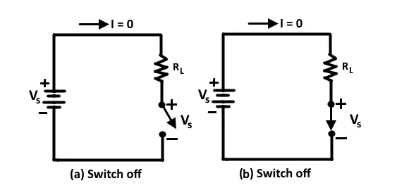
- The power losses generated in the switch is the product of the current through the switch and the voltage across the switch.
- When the switch is off, there is no current through it. And therefore, there is no power dissipation.
- When the switch is on, it has current but there is no voltage drop across it, so again there is no power loss.
- The ideal switch changes from the off state to on state instantaneously.The power loss during switching is zero.
Conduction Losses :
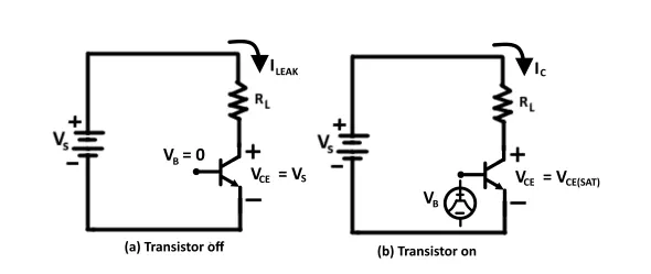
- When the transistor is off, it carries a leakage current. However, since the leakage current is quite small and does not vary significantly with voltage, it is usually neglected and thus the transistor power loss is essentially zero.
- When the transistor is on, it has a small voltage drop across it. The voltage is called the saturation voltage.
- The transistor power dissipation or conduction loss due to saturation voltage is :
`P_(ON) = V_(CE(SAT)) *I_C`
Where
IC = (VS - VCE(SAT)) / RL≈ VS / RL
Therefore, to find the voltage power loss we must consider the duty cycle :
PON(avg) = VCE(SAT) x Ic x (ION / T) = VCE(SAT) x IC x d
Similarly
POFF(avg) = VS x ILEAK x tOFF / T
Here, the duty cycle d is defined as the percentage of the cycle in which the switch is on :
d = tON / (tON x tOFF ) = tON / T
Switching Losses :
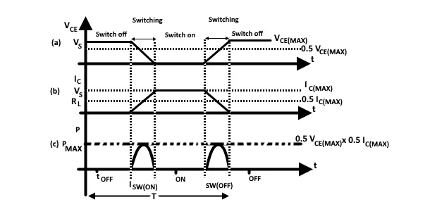
- In addition to conduction loss, a real switch has switching losses because it cannot change from the ON state to the OFF state instantaneously. A real switch takes a finite time to turn ON and a finite time to turn OFF.
- These times not only introduce power dissipation but also limit the highest switching frequency possible. The transition time for switching is generally larger. The figure below shows the switching waveform for (a) voltage source across the switch and current through it.
- When the switch is OFF the voltage across it is equal to source voltage.
- During turn-on, which takes a finite time, the voltage across the switch decrease to zero. During the same time current through the switch increases from zero to I_c. The transistor has current through it and a voltage across it during the switching time, therefore it has zero power loss.
STUDY - 2 :
For our simulation of the duty cycle, we are using a DC-DC converter. A DC-to-DC converter is an electronic circuit or electromechanical device that converts a source of direct current (DC) from one voltage level to another. It is a type of electric power converter. Power levels range from very low (small batteries) to very high (high-voltage power transmission).
There are many Different types of DC-DC converter available. But here we make only Buck Converter Circuit.
Step-down / Buck Converter :
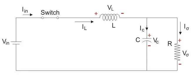
- The Step-Down converter or Buck converter reduces the input DC voltage to a specified DC output voltage.
- Timebased Modulation is mostly used for DC-DC Converter. It is simple to construct and use.
- The frequency remains constant in this type of PWM modulation.
The Buck converter has two modes of operation. The first mode is when the switch is on and conducting.
Mode 1 : Switch ON, Diode is OFF
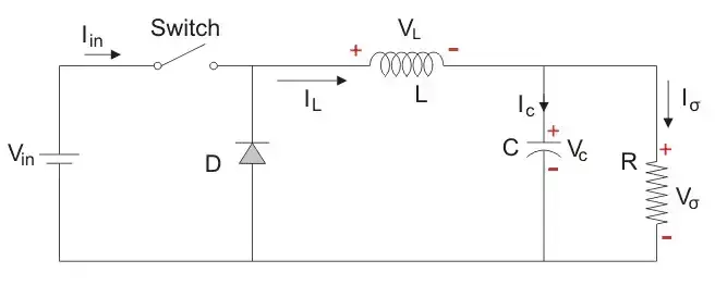
Mode 2 : Switch OFF, Diode is ON
Here, the energy stored in the inductor is released and is ultimately dissipated in the load resistance, and this helps to maintain the flow of current through the load.
Simulink Model For Generating Input Pulses :
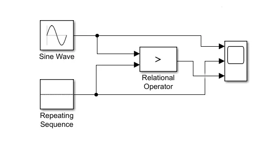
- Here we use a combination of two different wave generators as an input pulse generator. Sine wave and Repeating Sequence generator generate input signal.
- Relational Operator compares both signals which dependents on what condition it gives.
- The output signal of the Relational Operator is used to operate the switching action of Ideal switch.
- The scope is used to plot input signal waveform.
Sine Wave Input Block :
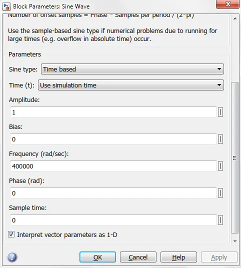
- Here we put input values for sine wave generator to generate an accurate waveform.
Repeating Sequence Input Block :
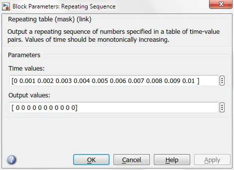
Output Plot For Pulse Generating Input Pulses :
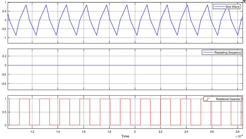
- The Above plot shows three different waveforms. In which first is sine wave and second repeating sequence. The third waveform is a comparison of the first and second waves.
- Relational Operator Block acts as a comparator.
- When the sine wave signal greater than the repeating wave then the relational operator produces a high output signal Otherwise it goes low.
Simulink Model For a Simple Buck Converter Circuit :
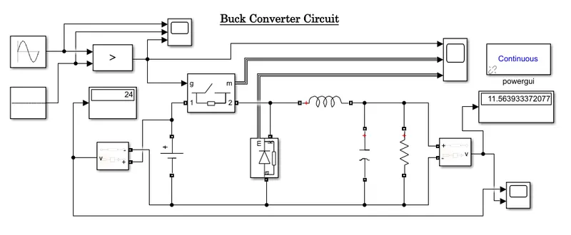
- In this MATLAB Simulink model, an ideal switch is used for regulating the 24V dc voltages in to 12V dc.
- The ideal switch is on or off through Relational Operator. The output of this converter is not pure dc it contains the high frequency harmonic content which are removed through low pass filter.
- In this model 1mH inductor and 1μF capacitor has been used such as low pass filter.1-ohm resistor has been used such as an output load.
Output Plot For Ideal Switch and Diode :
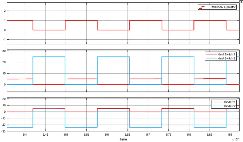
- The Above plot shows three different waveforms. Which first is relational block, second ideal switch block and third diode block .
- Whole plot shows the switching action of ideal switch and diode with a change in input signal.
Output Plot For Buck Converter Circuit :
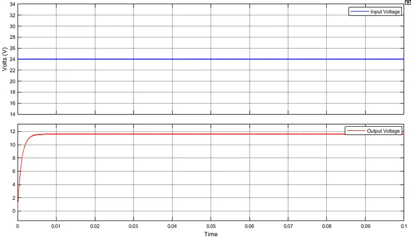
- From the above plot, we can see that it matches our result, the voltage at the output is reduced.
STUDY - 3 :
Variable Frequency Drive (VFD) :
- A VFD is a type of motor controller that drives an electric motor by varying the frequency and voltage supplied to the electric motor. Other names for a VFD are variable speed drive, adjustable speed drive, adjustable frequency drive, AC drive, microdrive, and inverter.
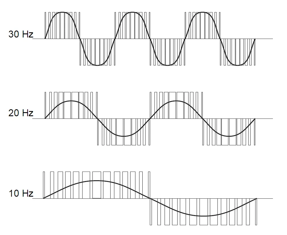
- Frequency (or hertz) is directly related to the motor’s speed (RPMs). In other words, the faster the frequency, the faster the RPMs go. If an application does not require an electric motor to run at full speed, the VFD can be used to ramp down the frequency and voltage to meet the requirements of the electric motor’s load.
- As the application’s motor speed requirements change, the VFD can simply turn up or down the motor speed to meet the speed requirement.
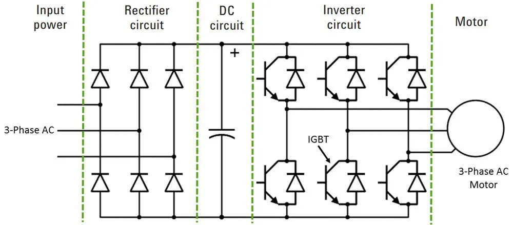
- VFD for AC motors have been the innovation that has brought the use of AC motors back into prominence. The AC-induction motor can have its speed changed by changing the frequency of the voltage used to power it. This means that if the voltage applied to an AC motor is 50 Hz (used in countries like China), the motor works at its rated speed.
- If the frequency is increased above 50 Hz, the motor will run faster than its rated speed, and if the frequency of the supply voltage is less than 50 Hz, the motor will run slower than its rated speed.
- According to the variable frequency drive working principle, it's the electronic controller specifically designed to change the frequency of voltage supplied to the induction motor.
Rectifier Stage :
- A full-wave power diode based solid-state rectifier converts three-phase 50 Hz power from a standard 220, 440 or higher utility supply to either fixed or adjustable DC voltage.
- The system may include transformers for high voltage systems.
Inverter Stage :
- Power electronic switches such as IGBT, GTO or SCR switch the DC power from the rectifier on and off to produce a current or voltage waveform at the required new frequency.
- Presently most of the voltage source inverters (VSI) use pulse width modulation (PWM) because the current and voltage waveform at the output in this scheme is approximately a sine wave.
Control Stage :
- Its function is to control output voltage i.e. voltage vector of the inverter being fed to the motor and maintain a constant ratio of voltage to frequency (V/Hz).
- It consists of an electronic circuit that receives feedback information from the driven motor and adjusts the output voltage or frequency to the desired values.
Advantages :
- Easy and simple control method.
- Constant Torque can be maintained.
Disadvantages :
- Range of control is less than Field oriented control.
- Efficiency is reduced due to stator drop compensation.
Vector Control Drive (VCD) :
- Vector control, also called field-oriented control (FOC), is a variable frequency drive(VFD) control method in which the stator currents of a three-phase AC electric motor are identified as two orthogonal components that can be visualized with a vector.
- One component defines the magnetic flux of the motor, the other the torque. The control system of the drive calculates the corresponding current component references from the flux and torque references given by the drive's speed control.
- A proportional-integral controller(PI) is used to keep the measured current components at their reference values. The pulse width modulation of the variable-frequency drive defines the transistor switching according to the stator voltage references that are the output of the PI current controllers.
- Vector control accordingly generates a three-phase PWM motor voltage output derived from a complex voltage vector to control a complex current vector derived from the motor's three-phase stator current input through projections or rotation back and forth between the three-phase speed and time-dependent system and these vectors' rotating reference-frame two-coordinate time-invariant system.
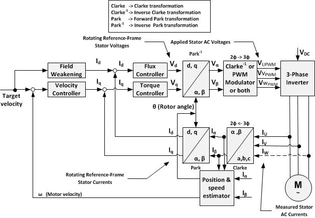
- Such complex stator current space vector can be defined in a (d,q) coordinate system with orthogonal components along with d (direct) and q (quadrature) axes such that the field flux linkage component of current is aligned along the d axis and the torque component of current is aligned along the q axis. The induction motor's (d,q) coordinate system can be
superimposed to the motor's instantaneous (a,b,c) three-phase sinusoidal system. - There are two vector control methods, direct or feedback vector control (DFOC) and indirect or feedforward vector control (IFOC), IFOC being more commonly used because in a closed-loop mode such drives more easily operate throughout the speed range from zero speed to high-speed field-weakening.
- In DFOC, flux magnitude and angle feedback signals are directly calculated using so-called voltage or current models. In IFOC, flux space angle feedforward and flux magnitude signals first measure stator currents and rotor speed for then deriving flux space angle proper by summing the rotor angle corresponding to the rotor speed and the calculated reference value of slip angle corresponding to the slip frequency.
Advantages:
- Improved torque response.
- Torque control at low frequencies and low speed.
- Dynamic speed accuracy.
- Reduction in size of motor, cost and power consumption.
- Four quadrant operation.
- Short-term overload capability.
Disadvantages:
- Complex method of control
VFD for EV Application :
- Practically, below 10 Hz (50 Hz motor) motor cannot start with full load when using V/F method.
- One solution is to add some boost voltage proportional to speed but it may result in saturating the motor (flux = v/f) but if it is wanted to run the motor down to zero speed it is not possible for VFD so we have to use Vector Control Drive or Direct Torque Control.
- So the precesize control of EV cannot be achieved and the overall efficiency of the vehicle will decrease as VFD is low efficient.
- In Electric Vehicles efficiency is the most important factor. VFD is simple but has higher amount losses in form of staor drop compensation and thus it is not so widely used in the EV industry.
- On the other hand Vector control method offers much better control at higher efficiency, hence it is preferred in Electric Vehicles.
CONCLUSION :
- A study of the Duty cycle control signal of the simple power converter circuit with the help of Buck-Boost Converter has been done.
- It has been found that, if the duty cycle is less than 0.5 it behaves as a buck converter circuit and if it is greater than 0.5 it behaves as a boost converter circuit.
- The vector Control method performs better than the VFD method, in terms of control for induction motor control in hybrid electric vehicles model, as it has fewer losses associated with it.
REFERENCES :
https://www.daenotes.com/electronics/basic-electronics/power-losses-in-switches
https://en.wikipedia.org/wiki/Vector_control_(motor)
https://www.electrical4u.com/buck-converter-step-down-chopper/
- Aakash KultheHi Brother. I need some help About this challenge. I contact You on the Linkedin.... When You see My message Reply me....