To create Simulink model for Given Functions and Study the Behaviour of "Mass-Spring-Damper System" by changing its parameters.
AIM : To create Simulink model for Given Functions and Study the Behaviour of "Mass-Spring-Damper System" by changing its parameters.
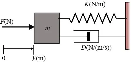
MASS-SPRING-DAMPER :
The mass-spring-damper model consists of discrete mass nodes distributed throughout an object and interconnected via a network of springs and dampers. This model is well-suited for modelling object with complex material properties such as nonlinearity and viscoelasticity. Packages such as MATLAB may be used to run simulations of such models. Objects may be described as volumetric meshes for simulation in this manner. As well as engineering simulation, these systems have applications in computer graphics and computer animation.
OBJECTIVE :
-
The force on a cutting tool of a shaping machine varies over the length of cut as follows :-
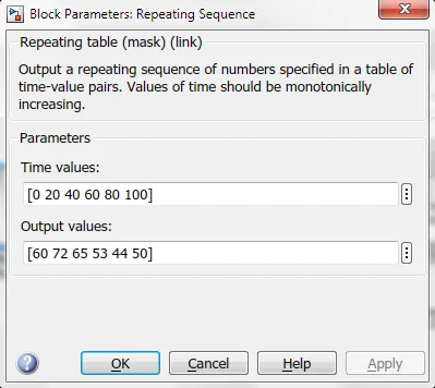
Distance (mm) 0 20 40 60 80 100
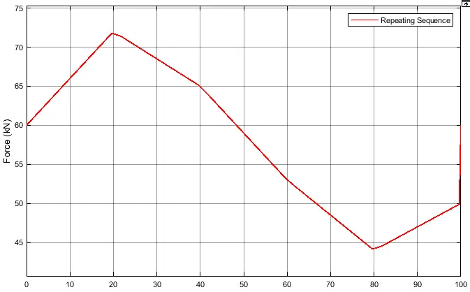
Force (kN) 60 72 65 53 44 50
Determine the work done as the tool moves through a distance of 100 mm.
-
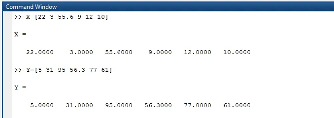
Create two array data sets x = [22 3 55.6 9 12 10] and y = [5 31 95 56.3 77 61] from the command window. Create a Simulink model to implement equation z = 3x2-5y+18 Store result values using To File block.
- Open the Pre Build Simulink model of “Mass-Spring-Damper System” and solve the following problems :-
- Derive the governing equation for the model.
- Change the value of mass, damper, and spring for the Simscape model and plot the result. Change the value of Mass x0=2 in the Simulink model and plot the results.
- Make the response from Simscape and Simulink as two separate displays.
SIMULINK MODEL FOR CALCULATING WORKDONE :
SIMULINK BLOCK EXPLANATION :
-
The total amount of work done can be calculated by the formula :
W = F * D
Where,
W = work done
F = Force acting on the tool
D = Distance travelled by the tool
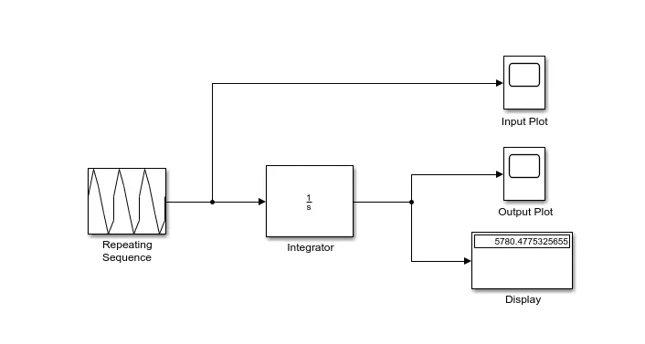
- Repeating Sequence block is generates the given force vs distance data into the signal data.
- The Integrator block outputs the value of the integral of its input signal with respect to time.
INPUT PARAMETERS :
FOR THE ABOVE BLOCK REPRESENTATION INPUT & OUTPUT PLOTS WOULD BE SHOWN BELOW :
INPUT REPEATING SEQUENCE PLOT :
OUTPUT INTEGRATOR PLOT :
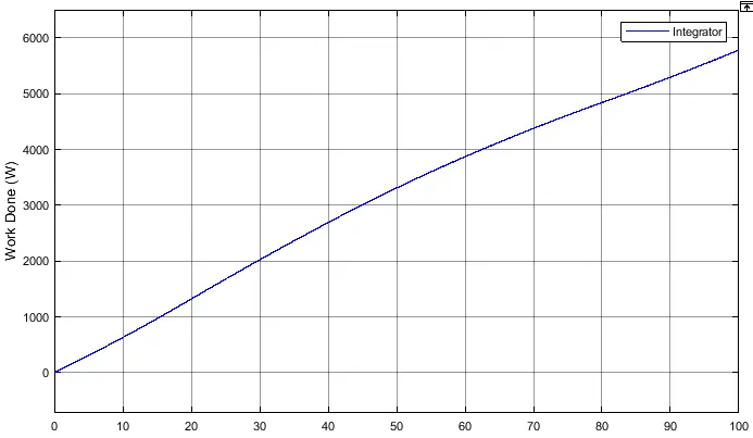
- Area under the above curve upto distance 'x' give the work done by the tool as it moves a distance of 'x' mm.
- From the graph and display in simulink model total work done by the cutting tool as it move 100mm is 5.780 kNmm or 5780 Nmm.
CONCLUSION : In this case the path is from 0-100(Time) and From (Point 1 - Point 6) is the distance of the boundary from the path. Finally Net Workdone has been calculated.
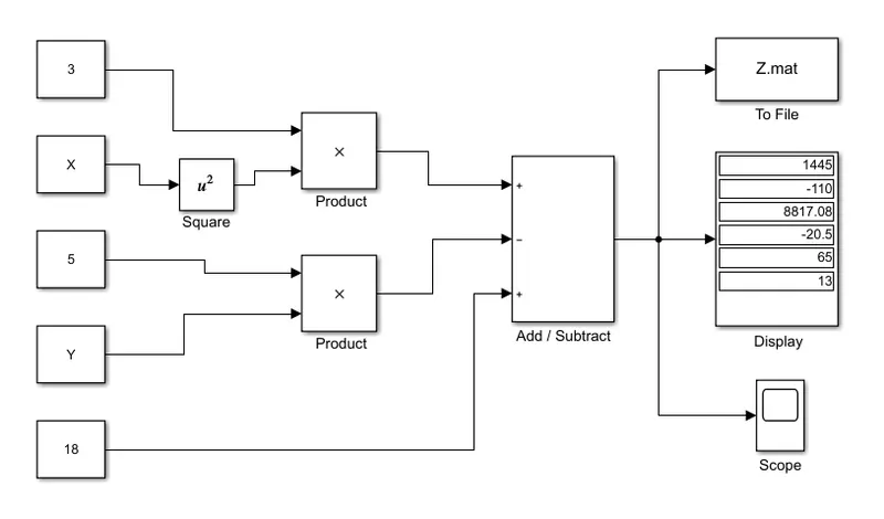
SIMULINK BLOCKS TO REPRESENT Z = 3x^2 - 5y + 18 FUNCTION :
SIMULINK BLOCK EXPLANATION :
- Here in the model common mathematical calculation blocks were used to form the equation. Variables X and Y were stored in the Matlab workspace and thereafter routed in the constant blocks in the initial stage of modelling.
- Now the equation is calculated in simulink by blocks. To create x an y block which the values are in workspace.
- Then constant blocks are used to insert all constant values. Product block is assigned for multiplying the constant values.
- Add / Subtract block is used to obatin addtion and subtraction function.
- An two array data sets X,Y from command window are created as per the given question. They are shown below :
- Given variables X and Y are created in the workspace as shown below :
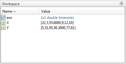
- The output value of the function Z = 3x^2 - 5y + 18 is stored in Z.mat file, They are shown below :
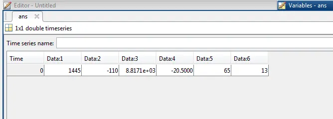
CONCLUSION : Simulink model reads the values from the array in model workspace and evaluates the function values and saves them in the file 'z.mat' using to file block.
MASS-SPRING-DAMPER :
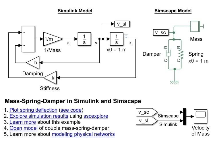
THIS BELOW BLOCK IS A PRE BUILD SIMULINK AND SIMSCAPE BLOCK :
THE GOVERNING EQUATION FOR THE ABOVE MODEL :
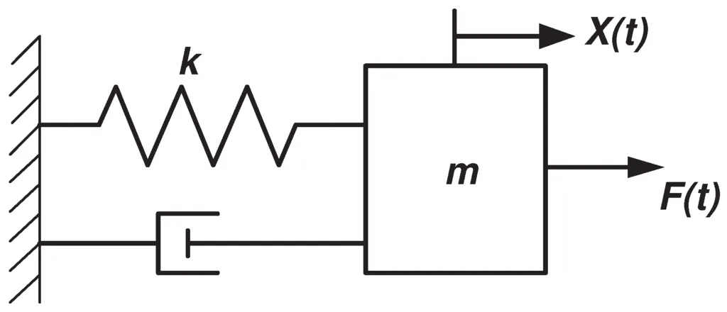
Where,
M = mass
K = Spring constant
C = Damper Coefficient
We know that:
`∑F=m.a` ………………… equation 1
Here,
`F_c=c*v`
`F_k=k*x`
Now, considering the sign conventions, (upward negative)
`-F_c-F_k=m*a` ………………… from equation 1
`-c.v-k.x=m*a`
Converting velocity & acceleration into displacement, we get:
`m ( d^2 x)/( dt^2 )= -c dx/dt-k.x`
Multiply throughout by`1/m`
`( d^2 x)/( dt^2 )= -c/m.dx/dt-k/m.x`
This is the final governing equation for this model.
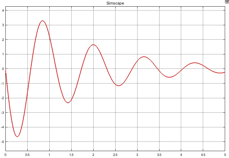
OUTPUT PLOT FOR THE SIMSCAPE MODEL :
After change the value of Mass, Damper and Spring :-
Mass (m) = 5 kg,
Initial condition as x0 = 1m
Stiffness (k) = 150
Damping (b) = 6
OUTPUT PLOT FOR THE SIMULINK MODEL :
After change the value of Initial condition (x0) :-
Mass (m) = 5 kg,
Initial condition as x0 = 2m
Stiffness (k) = 150
Damping (b) = 6
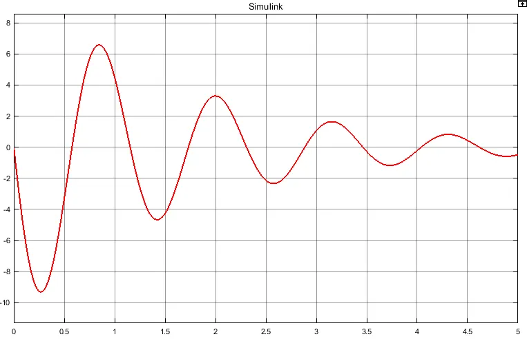
THE RESPONSE FROM SIMSCAPE & SIMULINK AS TWO SEPARATE DISPLAYS :
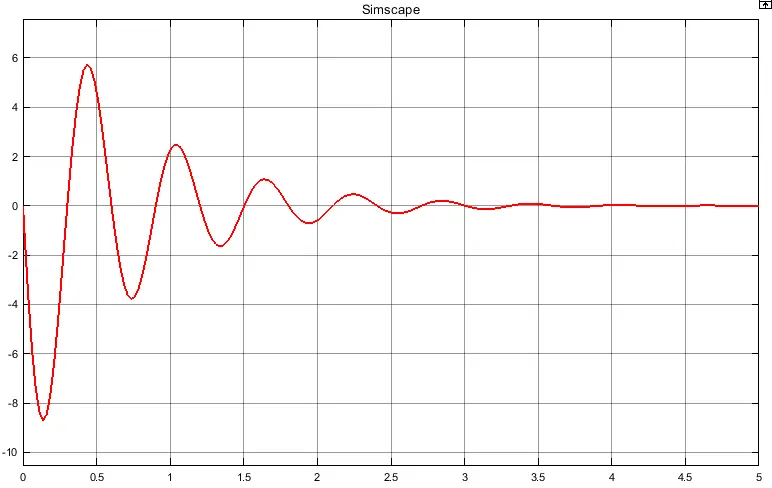
OUTPUT PLOT FOR THE SIMSCAPE MODEL :
Mass (m) = 3.6 kg,
Initial condition as x0 = 1m
Stiffness (k) = 400
Damping (b) = 10
OUTPUT PLOT FOR THE SIMULINK MODEL :
Mass (m) = 3.6 kg,
Initial condition as x0 = 1m
Stiffness (k) = 400
Damping (b) = 10
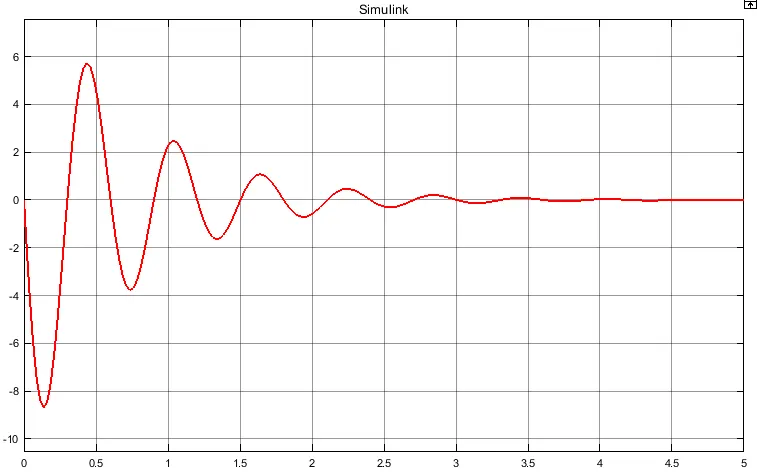
CONCLUSION : All the questions were completed successfully and the results are shown. The governing equation for spring-mass-damper system was derived successfully.