To Study about the types of Power Converter Circuits and To find out the EV steady state Speed for an electric vehicle’s Powertrain.
AIM : To Study about the types of Power Converter Circuits and To find out the EV steady state Speed for an electric vehicle’s Powertrain.
POWER ELCTRONICS :
Power electronics is the application of solid-state electronics to the control and conversion of electric power. The first high power electronic devices were mercury-arc valves. In modern systems, the conversion is performed with semiconductor switching devices such as diodes, thyristors, and power transistors such as the power MOSFET and IGBT.
In contrast to electronic systems concerned with transmission and processing of signals and data, in power electronics substantial amounts of electrical energy are processed. An AC/DC converter (rectifier) is the most typical power electronics device found in many consumer electronic devices, e.g. television sets, personal computers, battery chargers, etc. The power range is typically from tens of watts to several hundred watts. In industry a common application is the variable speed drive (VSD) that is used to control an induction motor. The power range of VSDs start from a few hundred watts and end at tens of megawatts.
GOVERNING EQUATION :
To solve the problem, we have used following formula :
Speed - Torque Equation,
' omega = V / (K Phi) - R_a / (K Phi)^2*T_m '
Where,
‘omega ' = Speed of the motor
' V ' = Supply Voltage
' Kphi ' = constant = ' E_b/omega '
' E_b ' = Back E.M.F
' T_m ' = Torque of moto
' R_a ' = Armature Resistan
OBJECTIVES :
-
To identify the types of power converter circuits employed in electric and hybrid electric vehicle.
-
To calculate the steady state speed of an EV with given inputs if duty cycle is 70%.
-
Refer to the blog on below topic :
Induction Versus DC brushless motors by Wally Rippel, Tesla
Explain in brief about author’s perspective.
STUDY - 1 :
POWER ELCTRONIC CONVERTERS :
- Power electronic converters are used everywhere in normal daily routines at home, commercial workplaces or in an industrial environment. Due to the high power handling with higher efficiencies, these converters become an integral part of industrial electric drives, high electric power supplies, electric traction systems and automobile control equipments.
- Power electronic technology deals with processing and controlling the flow of electrical energy in order to supply voltages and currents in a form that optimally suited for end user’s requirements.
- A power electronic converter uses power electronic components such as SCRs, TRIACs, IGBTs, etc. to control and convert the electric power. The main aim of the converter is to produce conditioning power with respect to a certain application.
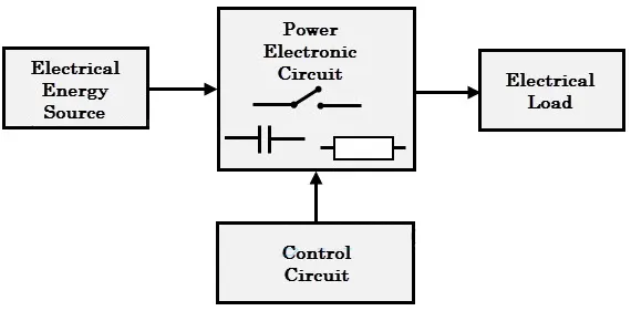
- The block diagram of a power electronic converter is shown in figure above. It consist of an electrical energy source, power electronic circuit, a control circuit and an electric load. This converter changes one form of electrical energy to other form of electrical energy.
- The power electronic circuit consists of both power part and control part. Power part transfers the energy from source to load and it consists of power electronic switches (SCR or TRIAC), transformers, electric choke, capacitors, fuses and sometimes resistors.
- The control circuit or block regulates the elements in the power part of the converter. This block is built with a complex low power electronic circuit that consists of either analog or digital circuit assembly.
- Power electronic converters perform various basic power conversion functions. This converter is a single power conversion stage that can perform any of the functions in AC and DC power conversion systems.
Depending on the type of function performed, power electronic converters are categorized into following types :
- AC to DC ( Rectifier )
- DC to AC ( Inverter )
- DC to DC ( Chopper )
- AC to AC ( Regulator )
AC to DC ( Rectifier ) :
- A rectifier is an electrical device that converts alternating current (AC), which periodically reverses direction, to direct current (DC), which flows in only one direction. The reverse operation is performed by the inverter.
- The process is known as rectification, since it "straightens" the direction of current. Physically, rectifiers take a number of forms, including vacuum tube diodes, wet chemical cells, mercury-arc valves, stacks of copper and selenium oxide plates, semiconductor diodes, silicon-controlled rectifiers and other silicon-based semiconductor switches. Historically, even synchronous electromechanical switches and motors have been used. Early radio receivers, called crystal radios, used a "cat's whisker" of fine wire pressing on a crystal of galena (lead sulfide) to serve as a point-contact rectifier or "crystal detector".
- Rectifiers have many uses, but are often found serving as components of DC power supplies and high-voltage direct current power transmission systems. Rectification may serve in roles other than to generate direct current for use as a source of power. As noted, detectors of radio signals serve as rectifiers. In gas heating systems flame rectification is used to detect presence of a flame.
- Depending on the type of alternating current supply and the arrangement of the rectifier circuit, the output voltage may require additional smoothing to produce a uniform steady voltage. Many applications of rectifiers, such as power supplies for radio, television and computer equipment, require a steady constant DC voltage (as would be produced by a battery). In these applications the output of the rectifier is smoothed by an electronic filter, which may be a capacitor, choke, or set of capacitors, chokes and resistors, possibly followed by a voltage regulator to produce a steady voltage.

DC to AC ( Inverter ) :
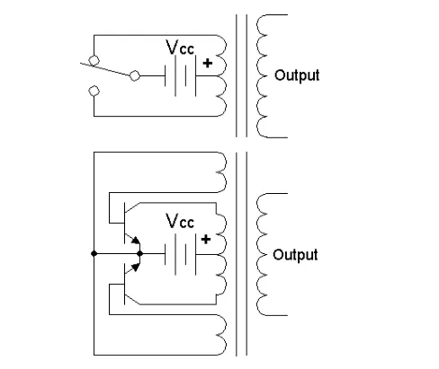
- A power inverter, or inverter, is a power electronic device or circuitry that changes direct current (DC) to alternating current (AC). The resulting AC frequency obtained depends on the particular device employed. Inverters do the opposite of “converters” which were originally large electromechanical devices converting AC to DC.
- The input voltage, output voltage and frequency, and overall power handling depend on the design of the specific device or circuitry. The inverter does not produce any power; the power is provided by the DC source.
- A power inverter can be entirely electronic or may be a combination of mechanical effects (such as a rotary apparatus) and electronic circuitry. Static inverters do not use moving parts in the conversion process.
- Power inverters are primarily used in electrical power applications where high currents and voltages are present; circuits that perform the same function for electronic signals, which usually have very low currents and voltages, are called oscillators.
DC to DC ( Chopper ) :
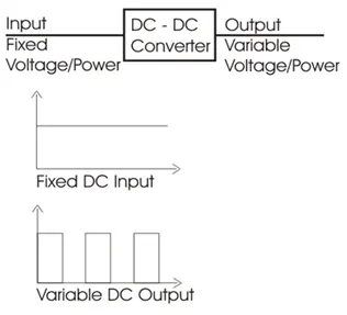
- In electronics, a chopper circuit is used to refer to numerous types of electronic switching devices and circuits used in power control and signal applications. A chopper is a device that converts fixed DC input to a variable DC output voltage directly. Essentially, a chopper is an electronic switch that is used to interrupt one signal under the control of another.
- In power electronics applications, since the switching element is either fully on or fully off, its losses are low and the circuit can provide high efficiency. However, the current supplied to the load is discontinuous and may require smoothing or a high switching frequency to avoid undesirable effects.
- In signal processing circuits, use of a chopper stabilizes a system against drift of electronic components; the original signal can be recovered after amplification or other processing by a synchronous demodulator that essentially un-does the "chopping" process.
AC to AC ( Regulator ) :
- A voltage regulator is a system designed to automatically maintain a constant voltage level. A voltage regulator may use a simple feed-forward design or may include negative feedback. It may use an electromechanical mechanism, or electronic components. Depending on the design, it may be used to regulate one or more AC or DC voltages.
- Electronic voltage regulators are found in devices such as computer power supplies where they stabilize the DC voltages used by the processor and other elements.
- In automobile alternators and central power station generator plants, voltage regulators control the output of the plant. In an electric power distribution system, voltage regulators may be installed at a substation or along distribution lines so that all customers receive steady voltage independent of how much power is drawn from the line.
STUDY - 2 :
TO FIND STEADY-STATE SPEED IF DUTY CYCLE IS 70% -
Given :
Rated Armature voltage = 72 V
Rated armature current = 400 A
Ra = 0.5Ω, KΦ = 0.7 Volt second
Chopper Switching frequency = 400 Hz
Soluton :
Speed-Torque equation of motor,
' omega = V/(K Phi)-R_a/(K Phi)^2*T_m '
For the value of 'V' we need multiply the Armature voltage with duty cycle -
therefore,
' V = 72*(70/100)=50.4 text(Volts) '
By susbstituting the values in Speed -Torque equation of motor we get,
' T_m = 70.56-0.98omega '
We have been given that Vehicle Speed Torque Characteristics as,
' T_v = 24.7+0.0051w^2 '
Where,
' T_v ' = Torque of the Vehicle
At Steady State,
' T_v = T_m '
By substituting the equations we get,
' 24.7+0.0051omega^2 = 70.56-0.98omega '
On solving this Equation we get the vaules of ' omega ' as,
' omega = 32.98, omega = -231.07 '
We are considering positive value of ' omega 'as we have taken it has forward motion.
STUDY - 3 :
According to the blog “Induction versus DC Brushless motors by Wally Rippel, Tesla”, the author wants to highlight topics related to EV technology, especially related to DC brushes and motors.
According to him, DC (direct current) is replaced by DC Brushless motors or Induction motors. Also, lead-acid battery is replaced by lithium ion batteries for EVs. He said that there will be the future of both the components induction and brushless DC motors depends upon their demands and uses.
DC Brushless motor :
The technology behind the DC Brushless motor is that it has more than 2 permanent magnet which generates a DC magnetic field. For better torque generation in rotor and stator, a current flow in winding and this happen due to magnetic field near the stator. According to him, the brushless motor needs a proper flow of current into rotor and stator if it will be not in a proper way then the current will not generate and there will be a decrease in torque. To maintain the electrical to mechanical conversion there should be a smooth flow of current otherwise this brushless motor is not useful. A brushless motor does not create any starting torque.
The advantage of a DC brushless motor is that there is low heat generation in the rotor, its cooling capacity is better as compared to induction motor drive, also peak power efficiency is high. Another difference is that the DC brushless drive, also peak power efficiency is high. Another difference is that the DC Brushless drive can also operate at unity power factor, whereas the best power factor for the induction drive is about 85 per cent. This means that the peak point energy efficiency for a DC Brushless drive will typically be a few percentage points higher than for an induction drive.
Induction motor :
The technology behind the induction motor is that it basically uses a 3-phase induction motor which was discovered by Nikola Tesla in 1889. In induction motor there is the use of steel laminated devise instead of magnets. Currents flowing in the stator windings produce a rotating magnetic field that enters the rotor. In an induction, motor current interacts with the magnetic field to produce a force which is required for rotor torque. The induction motor is compatible with any power sources. An induction motor cannot operate from DC voltage it always require AC voltage.
The induction motor does not have any magnets and in this the B field is adjustable. In an induction, motor B field is proportionate to V/f (voltage to frequency). This technology is used to reduce the magnetic losses and the overall efficiency will be increased. An induction motor has many advantages that it does not have any magnetic losses and conduction losses, due to which efficiency will maintain at maximum peak. This all lead to increasing the performance, induction motor is very useful and efficient for high performance. In an induction motor, the peak efficiency is less but it works smoothly better. The controlling of induction motor or mechanism is more complex. Also the torque generation is low and the motor temperature increases when it works at high speed.
CONCLUSION :
- We have discussed about the different types of power converter circuits employed in electric and hybrid electric vehicles.
- The EV steady state speed of an EV drivetrain was found out with the given input values.
- We have studied a blog on the topic Induction Versus DC brushless motors by Wally Rippel, Tesla and explained about the author’s perspective.
REFERENCES :
https://en.wikipedia.org/wiki/Power_electronics
https://www.electronicshub.org/4-different-power-electronic-converters/