To Study about the Thermal Management Systems.
AIM : To Study about the Thermal Management Systems.
OBJECTIVES :
-
Differentiate between the embedded C programming and model-based system approaches.
-
a.) Draw a high-level schematic of a remote controller toy car system. Explain the working principle of the toy car system.
b.) What are the differences between a remote control toy car and an actual electric vehicle ?
c.) State its limitations.
-
a.) Explain the cooling technologies of a power converter ?
b.) Take an example of a system and assume the efficiency and other parameters.
-
Refer to the below link and estimate thermal management system power requirement.
https://teslamotorsclub.com/tmc/threads/tesla-thermal-management-system-explanation.88055/
STUDY - 1 :
Difference Between the Embedded C Programming and Model-Based System Approaches :
Embedded C Programming -
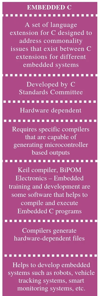
- Embedded C is a set of language extensions for the C programming language by the C Standards Committee to address commonality issues that exist between C extensions for different embedded systems.
- Embedded C programming typically requires nonstandard extensions to the C language in order to support enhanced microprocessor features such as fixed-point arithmetic, multiple distinct memory banks, and basic I/O operations. In 2008, the C Standards Committee extended the C language to address such capabilities by providing a common standard for all implementations to adhere to.
- It includes a number of features not available in normal C, such as fixed-point arithmetic, named address spaces and basic I/O hardware addressing. Embedded C uses most of the syntax and semantics of standard C, e.g., main() function, variable definition, datatype declaration, conditional statements (if, switch case), loops (while, for), functions, arrays and strings, structures and union, bit operations, macros, etc.
Model-Based System Design :
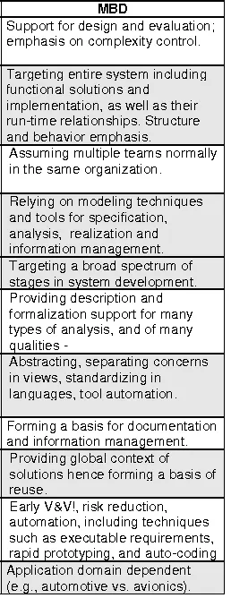
- Model-based design (MBD) is a mathematical and visual method of addressing problems associated with designing complex control, signal processing and communication systems. It is used in many motion control, industrial equipment, aerospace, and automotive applications. Model-based design is a methodology applied in designing embedded software.
- Model-based design provides an efficient approach for establishing a common framework for communication throughout the design process while supporting the development cycle (V-model). In model-based design of control systems, development is manifested in these four steps :
- modeling a plant,
- analyzing and synthesizing a controller for the plant,
- simulating the plant and controller,
- integrating all these phases by deploying the controller.
- The model-based design is significantly different from traditional design methodology. Rather than using complex structures and extensive software code, designers can use Model-based design to define plant models with advanced functional characteristics using continuous-time and discrete-time building blocks.
- These built models used with simulation tools can lead to rapid prototyping, software testing, and verification. Not only is the testing and verification process enhanced, but also, in some cases, hardware-in-the-loop simulation can be used with the new design paradigm to perform testing of dynamic effects on the system more quickly and much more efficiently than with traditional design methodology.
STUDY - 2 :
a.) A High-Level Schematic of a Remote Controller Toy Car System and Working Principle of it :
- Radio-controlled or remote-controlled toys, popularly called RC toys, are self-powered and can be controlled from a distance using a remote that works with radio waves.
- When we push the control, the transmitter sends a specific number of electrical pulses corresponding to that action through the air. The transmitter has its own power source, usually in the form of a 9-volt battery. Without the battery, the transmitter will not be able to send the radiowaves to the receiver.
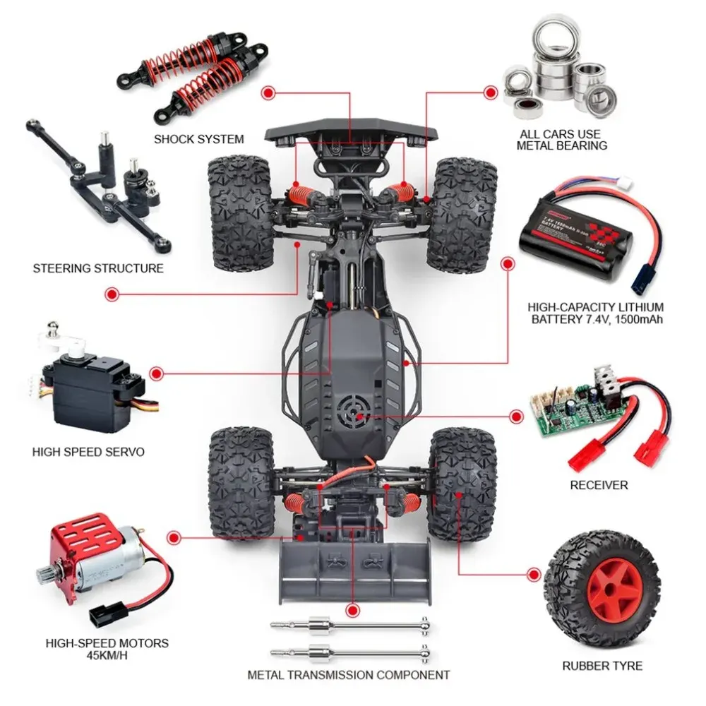
- Once the RC toy receives the radio waves, the motors kick into life to cause a specific action to occur. The power source sends power to all working parts, including the motor. The transmitter enables control through radio waves and the receiver activates the motors. When we press a button on the transmitter to make the RC toy go forward or backward, a pair of electrical contacts touch. Receiver identifies signals, sends it to circuit.
- Circuit board translates the number of electrical pulses (signals) into action. Full-function controllers have six controls and these works through following the pulse sequences :
-
Forward: 16 pulses
-
Reverse: 40 pulses
-
Forward left: 28 pulses
-
Forward right: 34 pulses
-
Reverse left: 52 pulses
-
Reverse right: 46 pulses
Parts of an RC toy -

Transmitter : The remote control contains a radio transmitter which operates on a particular frequency that the receiver is designed to receive.

Receiver : The receiver is fixed within the car and constantly receives signals from the transmitter. When a transmission is identified, it translates the number of electrical pulses into action.

Power source : All remote control cars require a power source. Rechargeable batteries power small electric motors. Alternatively, some use small internal combustion engines.

Motor and Circuit Board : The motor is responsible for the turning motions of the toy while the circuit board works like a pool through which all commands go on to specific parts.
- The remote controlled toy car circuit, consisting of an infrared transmitter-receiver pair, uses IR beam transmission to switch the toy car ‘on’ or ‘off ‘. To operate the toy car, you need to hold the transmitter in your hand, keeping it pointed at the toy car which has the receiver fitted inside, and simply press a switch provided on the transmitter.
- The transmitter works off 9V DC, while the receiver needs 6V DC. Bellow Figure shows the transmitter circuit. It is built around two BC558 transistors (T1 and T2), ,three BC548 transistors (T3, T4 and T5), IR LED1 and a few discrete components.
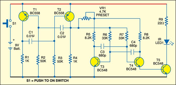
- Bellow Figure shows the receiver circuit. It is built around IR receiver module TSOP1738, two BC548 transistors (T6 and T7) and a few discrete components. In the transmitter circuit, there are two stable multivibrators. The first, built around transistors T1 and T2, produces a frequency of about 1.2 kHz. The second, built around transistors T3 and T4, produces about 38 kHz. IR LED1 is used to transmit the 38kHz frequency.
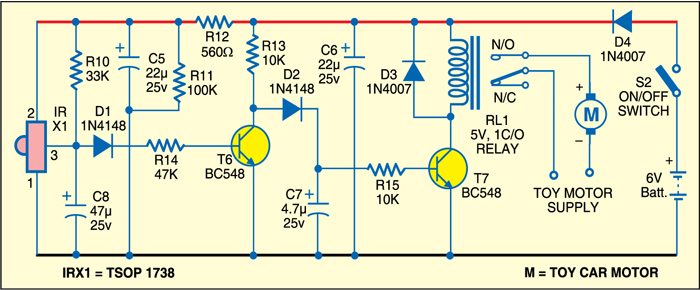
- In the receiver circuit, TSOP1738 receives the IR signal transmitted by IR LED1 of the transmitter circuit. The output of TSOP1738 is fed to transistor T6 via diode D1. The amplified signal is further given to relay-driver transistor T7. Relay RL1 energises to control the toy car.
- Working of the circuit is simple. Initially, when no IR beam is falling on sensor TSOP1738, the relay remains de-energised and the toy car doesn’t move. When switch S1 is pressed, the IR beam falls on TSOP1738 and its output goes low. Transistor T6 cuts off and transistor T7 conducts to energise relay RL1 and move the toy car.
- Assemble both the circuits on separate PCBs. Enclose the transmitter PCB in a suitable cabinet, with IR LED1 affixed on the front side and switch S1 on the top of the cabinet. Keep the 9V battery inside the cabinet.
- Enclose the receiver PCB inside the toy car, with TSOP1738 fitted such that the transmitted IR beam directly falls on it. Fix switch S2 on the body of the car and the relay inside the car. Use a 6V battery to operate the toy car receiver unit.
b.) Difference Between a Remote Control Toy Car and an Actual Electric Vehicle :
- In the Above Question, we see all about the Remote Control Toy Car.
- Now here we discuss the exact control logic and design of an Actual Electric Vehicle.
- Here we already observe a very huge difference taking place between a Remote Control Toy Car and an Actual Electric Vehicle.
- We know that Electric Vehicle is a very big scale operation.
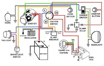
The actual car is made up of 2 main components -
- Adjoining and supporting components.
- Automobile Sensors.
Adjoining & Supporting components consist of –
Chassis and Frame -
- The chassis is formed by the frame with the frame side members and cross members. The frame is usually made of box, tubular and channel members that are welded or riveted together.
- In addition to this, it comprises of the springs with the axles and wheels, the steering system and the brakes, the fuel tank, the exhaust system, the radiator, the battery and other accessories. Along with this the frame supports the body.
Engine or Power Plant -
- The engine is the power plant of the vehicle. In general, internal combustion engine with petrol or diesel fuel is used to run a vehicle. An engine may be either a two-stroke engine or a four-stroke engine. An engine consists of a cylinder, piston, valves, valve operating mechanism, carburettor (or MPFI in modern cars), fan, fuel feed pump and oil pump, etc. Besides this, an engine requires ignition system for burning fuel in the engine cylinder.
Transmission System (Clutch and Gear Box) -
- The power developed by the engine is transferred to the wheels by transmission system. Transmission system must do three jobs :
- It must provide varying gear ratios. Number of gear ratios are equal to number of gears in a vehicle.
- It must provide a reverse gear for moving vehicle in reverse direction.
- It must provide a neutral or disconnecting arrangement so that the engine can be uncoupled from the wheels of the vehicle. In a conventional transmission system, there is a clutch, a manually operated transmission (gear box), a propeller shaft and a differential or final drive.
Clutch -
- The purpose of the clutch is to allow the driver to couple or decouple the engine and transmission. When clutch is in engaged position, the engine power flows to the transmission through it (clutch). When gears are to be changed while vehicle is running, the clutch permits temporary decoupling of engine and wheels so that gears can be shifted.
- In a scooter, the clutch is operated by hand where as in a car the clutch is operated by foot. It is necessary to interrupt the flow of power before gears are changed. Without a clutch, it will be very difficult.
Final Drive -
- Final drive is the last stage in transferring power from engine to wheels. It reduces the speed of the propeller shaft (drive shaft) to that of wheels. It also turns the drive of the propeller shaft by an angle of 90o to drive the wheels. The propeller shaft has a small bevel pinion which meshes with crown wheel.
- The crown wheel gives rotary motion to rear axles. The size of crown wheel in bigger than that of bevel pinion, therefore, the speed of rear axles (or crown wheel) in lower than the speed of pinion. Final drive is of two types, i.e. chain type and gear type.
Braking System -
- Brakes are used to slow down or stop the vehicle. Hydraulic brakes are generally used in automobiles, where brakes are applied by pressure on a fluid. Mechanical brakes are also used in some vehicles. These brakes are operated by means of 9 Introduction to Automobile Engineering leavers, linkages, pedals, cams, etc. Hand brake or parking brake is usually a mechanical brake. These are used for parking the vehicles on sloppy surfaces and also in case of emergency.
Gear Box -
- Gear box contain gearing arrangement to get different speeds. Gears are used to get more than one speed ratios. When both mating gears have same number of teeth, both will rotate at same number speed. But when one gear has less teeth than other the gear with less number of teeth will rotate faster than larger gear In a typical car there may be six gears including than other, the gear with less number of teeth will rotate faster than larger gear.
- In a typical car, there may be six gears including one reverse gear. First gear gives low speed but high torque. Higher gears give progressively increasing speeds. Gears are engaged and disengaged by a shift lever.
Steering System -
- In front wheels can be turned to left and right by steering system so that the vehicle can be steered. The steering wheel is placed in front of driver. It is mechanically linked to the wheels to provide the steering control.
- The primary function of the steering system is to provide angular motion to front wheels so that vehicle can negotiate a turn. It also provides directional stability to vehicle when the vehicle moves ahead in straight line.
- Now-a-days, many vehicles are equipped with power steering which uses pressure of a fluid to reduce steering effort. When driver turns the steering wheel, a hydraulic mechanism comes into play to provide most of the effort needed to turn the wheel.
Front Axle -
- Front axles are mounted at the end of front axle. A part of the weight of vehicle is transmitted to the wheels through this axle. The front axle performs several functions.
- It carries the weight of the front of the vehicle and also takes horizontal and vertical loads when vehicle moves on bumpy roads. When brakes are provided on front wheels, it endures bending stresses and torsional stresses. It is generally made from steel drop forging. It is robust in construction.
Suspension System -
- Suspension system of an automobile separates the wheel and axle assembly of the automobile from its body. Main function of the suspension system is to isolate the body of the vehicle from shocks and vibrations generated due to irregularities on the surface of roads.
- Shock absorbers are provided in the vehicles for this purpose. It is in the form of spring and damper. The suspension system is provided both on front end and rear end of the vehicle. A suspension system also maintains the stability of the vehicle in pitching or rolling when vehicle is in motion.
Automobile Sensors –
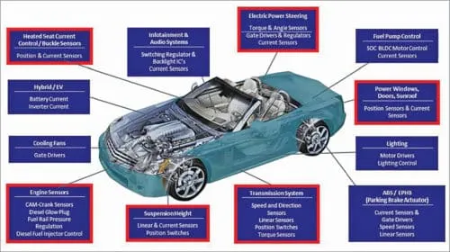
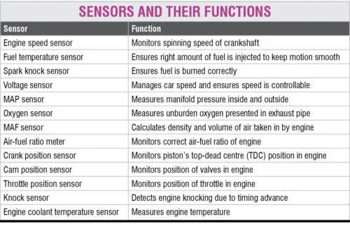
c.) limitations of Actual Electric Vehicle :
Although the evidence of the positives has become very clear, there are also some downsides that each individual needs to consider before they decide to make an electric car their next big investment. These reasons are :
Recharge Points -
- Electric fuelling stations are still in the development stages. Not a lot of places you go to on a daily basis will have electric fuelling stations for your vehicle, meaning that if you’re on a long trip or decide to visit family in a rural or suburban area and run out of charge, it may be harder to find a charging station. You may be stuck where you are.
- However, until charging stations are more widespread, be sure to have a charging station maps where you live and where you frequently go so that you’ll be able to charge your new EV when you need to.
The Initial Investment is Steep -
- As EVs are very new, you may be surprised when you take a look at the sticker price for EVs. Even the more affordable brands can be around $30,000 to $40,000.
- If you’re looking for a luxury option, you may be paying $80,000 or even more. Though technology is advancing and the price to produce electric cars continues to drop, you still have to pay $10,000 to $50,000 more for an EV than for a gas-powered car.
Electricity isn’t Free -
- Electric cars can also be a hassle on your energy bill if you’re not considering the options carefully. If you haven’t done your research into the electric car you want to purchase, then you may be making an unwise investment.
- Sometimes electric cars require a huge charge to function properly – which may reflect poorly on your electricity bill each month.
Short Driving Range and Speed -
- Electric cars are limited by range and speed. Most of these cars have a range of about 50-100 miles and need to be recharged again. You just can’t use them for long journeys as of now, although it is expected to improve in the future.
Longer Recharge Time -
- While it takes a couple of minutes to fuel your gasoline-powered car, an electric car takes about 4-6 hours and sometimes even a day to get fully charged.
- Therefore, you need dedicated power stations as the time taken to recharge them is quite long. Thus, the time investment and necessary planning do put some people off.
- There are some kits that can cut the charging time down. But again, that is going to be an additional investment. So consider that, too.
Silence as a Disadvantage -
- Silence can be a bit disadvantage as people like to hear the noise if they are coming from behind them. An electric car is, however, silent and can lead to accidents in some cases.
Normally 2 Seaters -
- Most of the electric cars available today are small and 2 seated only. They are not meant for the entire family, and a third person can make a journey for the other two passengers a bit uncomfortable.
Battery Replacement -
- Depending on the type and usage of battery, batteries of almost all electric cars are required to be changed every 3-10 years.
Not Suitable for Cities, Facing Shortage of Power -
- As electric cars need the power to charge up, the cities that already facing acute power shortages are not suitable for electric cars. The consumption of more power would hamper their daily power needs.
Lower Amount of Choices -
- The market today for electric cars is expanding, with no signs of slowing down. However, the truth is that there are fewer options to customize and choose the aesthetics of your EV.
- At the same time, the vast amount of customization is available with traditional cars. This is likely to change over time, but for many people, it is going to be a disadvantage.
Minimal Amount of Pollution -
- Electric vehicles are also not 100% emission-free; they cause a little amount of pollution indirectly. The batteries and electricity needed for charging are not necessarily generated from renewable energy sources.
STUDY - 3 :
a.) The Cooling Technologies of a Power Converter :
- A high-density dc-dc converter can deliver substantial power, but only if excessive heat is removed by transferring internal heat through a number of material interfaces to a surface exposed to the surrounding air. High power LED light fixtures present an additional challenge: light output can drop off sharply right at the start and decrease further over time if cooling is not adequate. Here are steps engineers can take to improve cooling performance.
- The heat removal challenges are more complex because of the required form factors. That means even at power levels as low as 7-10 watts, these designs need more attention so that LED chips do not overheat.
- From a thermal management standpoint, a high-density dc-dc converter, like virtually all power supplies, can deliver substantial power, but only if excessive heat is removed by transferring internal heat through a number of materials to a surface exposed to surrounding air. Heat from that outer surface is then transferred to the surrounding air in proportion to the air turbulence immediately adjacent to that surface, whether that “turbulence” results in the form of fast-moving air (active cooling) or very tiny air “eddy currents” in a passively cooled system.
- The reference to “outer surface” needs a further comment because no mention was made of a “metal” surface. The reason for this is that in a perfect situation all of the internal heat would originate from every cubic millimeter within the module and would be evenly distributed to all parts of the outer surface. Whether the outer surface is plastic or metal makes no difference as long as there is no effort to attach one of the hot surfaces to a heat sink; that is, as long as there is only (surface-to-air) convection cooling.
- In a real world power module or light fixture, specific components (which can be either traditional power semiconductor or power LEDs) are the principal heat generators. The area adjacent to these components is usually hotter than other areas. An outer metal case or plate spreads the heat and reduces point-to-point temperature variations. With a high-density converter having a metal baseplate, the thermal conductivity of the plate material is an indispensable link to a cooling technique, which is better than simple surrounding air.
- The baseplate has two functions: to spread the heat generated by small-surface-area power semiconductors and to conduct that heat to a cooler place. For the remainder of this discussion, the concentration will be on heat removal from the power semiconductors within the converters (or light fixtures) because they usually represent over 85% of the internally generated heat.
- The process which final surface-to-air heat makes transfer is what determines the ultimate ability of a converter to deliver its maximum possible power. The barrier to perfect heat transfer is defined as “thermal resistance,” that is, the lower the thermal resistance, the better the heat transfers. Stated another way, the higher the thermal conductivity, the better.
- However, it has become the convention in addressing power semiconductor and power supply thermal management to talk in terms of “thermal resistance” instead of thermal “conductivity.”
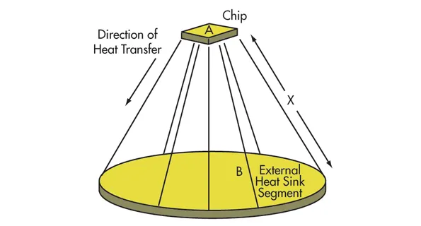
- In practice, internal heat is never perfectly distributed and there are hot spots. Above Fig. shows how heat from a point source, such as the chip within a MOSFT or power rectifier package reaches its destination. Heat travels outward in a conical path that is rarely a perfect cone because of the physical configuration of heat generators. Below Fig. depicts the same process in a way that reflects the typical arrangement for heat removal from the power semiconductor in a dc-dc converter.
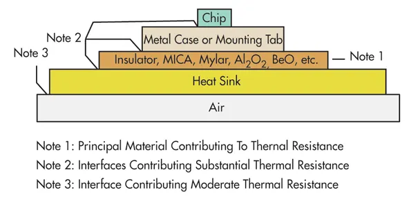
The ability of heat to get from one place (such as the chip) to another (the surrounding air) is determined by :
- The distance (thickness).
- The area (a large glass window transfers or loses heat faster than a small windoww.
- Thermal resistance of the various materials and interfaces through which the heat must pass.
Often not appreciated is the fact that a material of given thermal resistance has a more adverse effect the closer it gets to the point source of heat. Conversely, the actual thermal resistance of a given thickness of material becomes less important the more it is at the wide end of the het travel cone. This means that an infinite amount of heat sinking and airflow cannot keep the chip cool if the chip-to-case and case-to-heat sink surfaces have excessive thermal resistance. In some applications, the simple change to a chip of larger area and correspondingly lower junction-to-case thermal resistance could have more effect than an exotic fan and heat sink system.
Cooling Methods :
A converter’s heat transfer can be enhanced by using one or more of the following techniques to lower the thermal resistance, i.e., the thermal conductivity from the internal converter heat sources to the outer air :
- Use a large metal enclosure to expose more of the heated metal surface to the air, essentially enlarging the conical heat pipe diameter at the open end of the thermal cone. This option is not really available in a high-density converter because by definition, the high-density module footprint is probably small.
- Blow air across the baseplate or metal surfaces of the case. The additional air turbulence at the metal surface speeds up the heat removal process by enlarging the cone’s large-end diameter. With converters, the degree of cooling for specific air speeds and area for the metal surface has been characterized. Typically, an air speed of 200 linear feet per minute (lfm), readily achieved with standard fans, is desired across the heat surface or heat sink fins in order to achieve substantial cooling. Air speeds much above 400-500 lfm are usually difficult to achieve in constricted areas and at the same time become marginally effective in removing much more heat.
- Attach the case to a larger metal surface (spreading the heat) to expose more surface area to the surrounding air (similar to item 1). Often, this is not feasible unless there is a large aluminum chassis to which the unit can be attached.
- Attach the baseplate to a finned heat sink across which air is blown. In the presence of air flow, the extra surface of the fins just like additional external unfinned metal surface area, as in item 3, but confines the extra within a more compact volume. It is important to understand that fins do not have much effect unless there is airflow in the direction of the fins. Cooling with finned heat sinks is generally the most effective practical cooling scheme for converters. For a given air flow, one inch-high fins can double the cooling effect over a baseplate without fins.
Fin spacing, fin height, air speed and air direction all contribute to the final effectiveness. A common mistake by designers is to dwell on the cubic-feet-per-minute (cfm) rating of fans when making assumptions about system cooling. The cfm of the fan tells us about the volume of air that is to pass immediately over the surface of the hot metal surface. It is the speed in linear feet per minute that is important.
A small fan, in a creative configuration with a finned heat sink, can dramatically outperform a large fan with a poorly thought-out fin arrangement. In the same way a small battery-operated hand-held fan six inches from ones face can cool far better than a giant fan 50 feet away.
An infinite number of possible schemes can be conceptualized, but there are a number of basic finned heat sink configurations, which, if used conservatively, will ensure proper cooling.
In cooling a converter, it is always understood that system assembly practices, unexpected changes in available air, or ambient temperatures may result in the converter being cooled a little less optimally than thought. Nevertheless, using the recommended finned heat sinks will prevent catastrophic failures under normal conditions.
b.) An Example of a System and assume the Efficiency and other Parameters :
Example : The power dissipated in this MGDS module at 28Vdc input voltage & used at full load power 10 W is -
The efficiency of this module at full load 10W & 28Vdc input voltage is 86%.
The power dissipation is the function of the power used & DC/DC converter efficiency.
P-Dissipation = (P-used/efficiency – P-used).
In this example we find P-Dissipation = 1.6 W.
The power dissipated is transformed into heat.
Heat Transfer –
- The primary gaol in the thermal design is to predict and control the converter’s heat so that it doesn’t exceed the maximum rating of temperature admissible by the DC/DC converter.
- Heat energy is transferred from regions of high temperature to regions of low temperature via three basic mechanisms –
- Radiation – Electromagnetic transfer of heat between masses at different temperatures.
- Conduction – Transfer of heat through a solid medium (For e.g. – Heat Sink).
- Convection – Transfer of heat through the medium of fluid (Typically air from ventilation).
- All three of these heat transfer mechanisms are active to some degree in every application. All three of these mechanisms should be given consideration when developing thermal management systems.
Radiation Transfer –
- Thermal radiation is transfer of heat by electromagnetic radiation (Primarily in the infra-red wavelengths). Radiation is the only means of heat transfer between bodies separated by a complete space vacuum. Many factors contribute to thermal radiation efficiency, such as temperature differentials, surface area & Surface emissivity. Black anodized aluminium is a good thermal medium to take advantage of radiated heat.
- A heatsink with a large area for a given volume will take maximum advantage of radiation. But radiation is minor contributor to the overall thermal link in most power converter applications and counts in majority of cases for less than 5% of total heat transfer. It is best to use the effects of radiation as a safety margin in the thermal design, since its contributions to heat transfer will normally be small & is difficult to quantify & requires relatively larger heatsink area to be efficient.
Conduction Transfer –
- Heat is transferred through a solid medium by conduction and it is most fundamental of all thermal mechanisms. Thermal conduction can be understood as analogue as conduction of electrical current in a wire.
- As the electrical current in a wire is a function of the different electrical current resistances and voltage drop, the thermal transfer is a function of the different thermal resistances and temperature drop from one point to another.
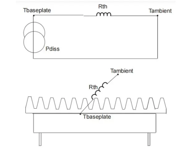
The thermal resistivity of a uniform conducting membrane can be defined as – R = L/K*A
Where,
R = Thermal Resistance (Degree Celsius/Watt).
L = Length or width (Inch or mm).
A = Cross Sectional Area (Inch or mm ).
K = Material Thermal Conductivity (Watt/inch degree Celsius or mm degree Celsius).
Convection Transfer -
- Heat transfer by convection (Natural or Forced) involves the transfer of heat to a surrounding fluid by conduction, typically air.
- This mode of heat transfer is dependent on a number of variables and is somewhat complex to calculate. Surface area, Temperature Gradient, Thermal conductivity, of fluid (Air), Velocity of fluid (Air) density & other variables affect convection.
Natural Convection -
- Natural convection is sometimes also referred as free convection. Natural convection is easier to implement than forced convection, but at the expense of increased thermal resistance.
- Natural convection produces its own air velocity. due to the local heating of air at the heatsink surface. The air density is reduced when heated. Causing it to rise, thus causing the air movement. Natural convection is not as effective at higher altitudes due to air density reduction. Free air movement across a thermal dissipater is required to perform adequately. Confined air would not conduct natural convection & the following rules apply –
- Mount heat sinks so the max. length of convection surfaces (Fins) are in the vertical plane.
- Place the heat sink above the converter, allowing air to rise above.
- Provide sufficient enclosure ventilation for natural convection of the air.
- Note that heatsink fin spacing will reduce the effectiveness of the heatsink.
- Due to complexity to calculate heat transfer for only free air convection, majority of DC/DC converter manufacturers are given their thermal resistance performances in free air convection condition (which will include conduction and natural convection).
STUDY - 4 :
Tesla Thermal Management System :
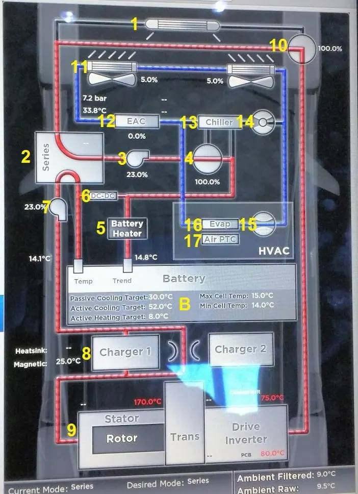
Systems Functions –
Cooling –
- Due to inefficiency, battery cells will not only generate electricity but also heat. This heat should be moved from the battery pack when battery temperature reaches the optimum temperature or even in advance. Thus, a cooling function is required in BTMS.
Heating -
- In cold climates, battery pack temperature probably falls below the lower temperature limit. Hence, a heating function, such as PTC heater, is required to assist the battery pack to reach the proper temperature range in a shorter time.
Insulation –
- In extreme cold or hot weather, the temperature difference between the inside and outside of the battery pack is much larger than that in mild weather. Battery temperature will thus fall (cold) or rise (hot) sooner out of the proper temperature range. To prevent this, good insulation can slow down the falling or rising of battery temperature, especially when the vehicle is parked outdoors.
Ventilation –
- Ventilation is required to exhaust the hazardous gases within battery pack. In some systems, such as air systems, this function is combined with cooling and heating functions.
Technologies of BTMS –
- Technologies of BTMS
- Forced air systems (passive and active).
- Forced air system with heat recovery.
- Passive liquid cooling system.
- Active liquid cooling system.
- Direct refrigerant cooling system.
- Thermoelectric cooling/heating system.
Combined Colling Systems –
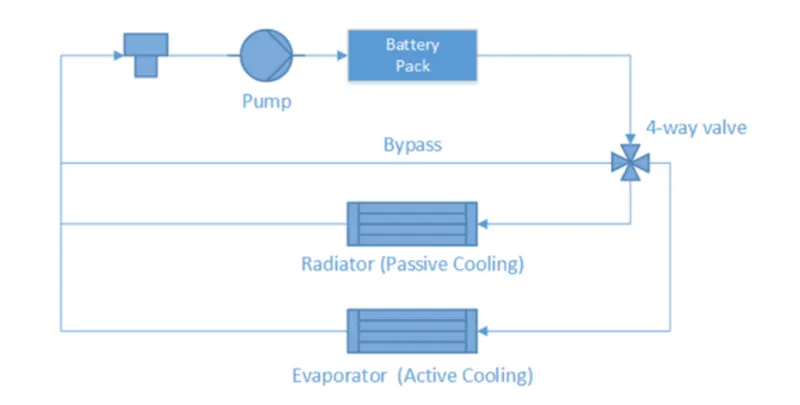
The first is the liquid cooling system, which has four working modes : bypass with heater working, bypass without heater working, passive cooling system, and active cooling system.The cooling system takes advantage of both passive cooling system and active cooling system. Passive cooling system has simple structure and is able to dissipate heat under normal conditions with low energy consumption. Under extreme condition, active cooling system has good thermal performance to keep battery temperature in the required range.
Initial inputs and thermal cycles settings –
- Starting with the battery unit, physical parameters such as thermal capacity and mass were defined as fixed parameters. When the PCM is located close to the battery cell, these two parts could be treated as one integrated part. Thus the PCM in this case could be considered a part within the battery unit. Focusing on the thermal issues of the battery pack, there are two main parts of heat transfer flows that influenced the battery temperature. One was the heat generation internally.
- This part depended on driving behaviour, battery features and other vehicle parameters, such as vehicle mass and aerodynamic performance. Since this thesis focused on thermal rather than electro-thermal issues, this interior heat was generated by exterior electro-thermal model.
- The other part was the external heat dissipation. This part of the heat was from the different thermal cycles which took away certain amounts of heat from the battery or in some cases brought heat to the battery. The amount of heat depended both on which thermal cycle was chosen and surrounding thermal conditions. Therefore, some parameters were collected from the battery unit and testing conditions for calculation. After this step the required battery thermal model was built.
Control strategy development –
- Normally, there are more than two thermal cycles designed in battery thermal models. To decide which cycle to operate, some characteristic parameters were required, such as battery temperature and ambient temperature. According to these parameters, an operation state was chosen.
- The state corresponding to the thermal cycle that was active and some related components, forexample, the pump would change their operating state as well. In some cases a sub-state under the main operation state could be introduced in order to achieve better operation feature.
Simplification and decoupling –
- Some complex calculation cases would give endless loops thus a simplified or approximate calculation method should be adopted to solve the endless loops and to accelerate the simulation.
- In other cases, decoupling was an alternative solution. For example, the activated thermal cycle consumes electricity, causing additional load and consequently additional heat. This coupling between the thermal model and electro-thermal model would cause unexpected programming issues. Thus, it was better to decouple these two models at the beginning and connect them later when both of them worked well.
Data process and output –
- Not all output parameters were meaningful. Only parameters which represented the outcome of the model were recorded.
- Some raw data was processed into performance parameters in order to evaluate different results with a common standard. For a better visual understanding, some figures were also plotted based on numerical data.
Modelling Parameters -
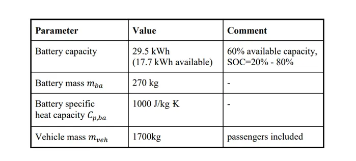
Also, a few parameters varied in order to represent different situations. The most important variable parameters were :
Ambient temperature (𝑻𝒂𝒎𝒃) -
- This temperature represented the climate conditions of the atmosphere around the driving vehicle. When it ranged from -20°C to 10°C, it was considered to be a cold climate. When it ranged from 10°C to 20°C, it was considered to be a mild climate. When it ranged from 20°C to 40°C, it was considered to be a hot climate.
Battery initial temperature (𝑻𝒃𝒂,𝒊𝒏𝒊) -
- It’s normally considered that battery initial temperature is exactly equal to ambient temperature. But when pre-conditioning is applied, these two temperatures are not the same. Battery initial temperature is higher than ambient temperature when the battery is pre-heated in a cold climate. Battery initial temperature is lower than ambient temperature when the battery is precooled in a hot climate. Different levels of pre-conditioning could be adopted.
Desired temperature (𝑻𝒅𝒆𝒔) -
- The desired temperature represents the temperature that the control unit of the BTMS aims for, i.e. the optimum operating temperature point stated by the manufacturer. With different thermal cycles the BTMS will try to control battery temperature as close as possible to the desired temperature. In most cases of this work 𝑇𝑑𝑒𝑠 is 25°C, but some special cases with 𝑇𝑑𝑒𝑠= 20°C were also tested.
Testing driving cycle -
- This model focuses more on the BTMS feature during driving. Two driving cycles were chosen to represent two different driving behaviours : One was US06 whose vehicle speed profile. This driving cycle lasts 596 seconds per single cycle. It has an aggressive driving behaviour with maximal speed of 129 kph and an average speed of 77.9 kph.
- The other is the NEDC (New European Driving Cycle) representing a mild driving behaviour. It lasts 1180 seconds per single cycle with maximal speed of 120 kph and an average speed of 33.9 kph. For testing, each was chosen as a testing condition input and the vehicle was driven following the speed profile until the available battery capacity (17.7 kWh) was exhausted.
- This complete cycle is called Testing Driving Cycle (TDC) which consisted of several driving cycles. The whole TDC NEDC lasted 16229 seconds and TDC US06 5139 seconds. According to the different TDC, the corresponding heat generation rate profile was calculated through exterior electrothermal model and the profile of the NEDC. Another heat generation rate profile by US06 was generated in the same way.
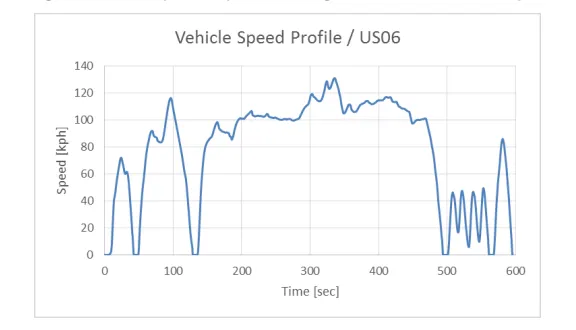
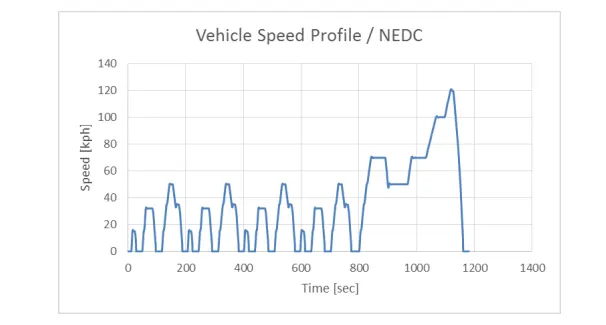
- CLS Model Based on the system layout of, a MATLAB/Simulink model was developed following the four steps mentioned at the beginning of this chapter. A basic model layout is shown in the following Figure. In the basic layout, the temperature flow of heat transfer fluid connects the main parts together.
- In initial step, testing data was loaded. Then starting with the battery unit the fluid was heated up. Afterwards, the fluid flows through different parts, but only one outcome was chosen by control unit. The flow rate of the pump was also governed by control unit. Lastly, the coolant returned to battery pack. This calculation process was repeated until the driving cycle ended.
CONCLUSION :
-
Successfully Differentiate the embedded C programming and model based system approaches.
-
Successfully Drawrn a high-level schematic of a remote controller toy car system and Explained the working principle of the toy car system.
-
Discussed the cooling technologies of a power converter.
REFERENCES :
https://en.wikipedia.org/wiki/Embedded_C
https://en.wikipedia.org/wiki/Model-based_design
https://www.businesstoday.in/magazine/how-things-work/rc-toys-radiowaves/story/17649.html
https://www.conserve-energy-future.com/advantages-and-disadvantages-of-electric-cars.php