To implement control logic of a “Washing Machine” using Stateflow And Make a Simulink chart for the “Gear Shift” logic as per given conditions.
AIM : To implement control logic of a “Washing Machine” using Stateflow And Make a Simulink chart for the “Gear Shift” logic as per given conditions.
STATEFLOW :
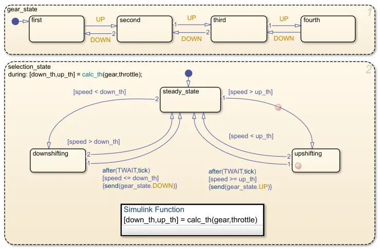
Stateflow (developed by MathWorks) is a control logic tool used to model reactive systems via state machines and flow charts within a Simulink model. Stateflow uses a variant of the finite state machine notation established by David Harel, enabling the representation of hierarchy, parallelism and history within a state chart. Stateflow also provides state transition tables and truth tables. Stateflow is generally used to specify the discrete controller in the model of a hybrid system where the continuous dynamics (i.e., the behavior of the plant and environment) are specified using Simulink.
Specific applications for Stateflow include :
- Mode logic, where each discrete mode of a system is represented by a state.
- Fault management, where the Stateflow chart is used to control how the system responds to faults and failures within a system.
- Task scheduling, where the Stateflow chart is used to schedule when specific tasks occur, either within the Stateflow chart or within the overall Simulink model.
WASHING MACHINE :
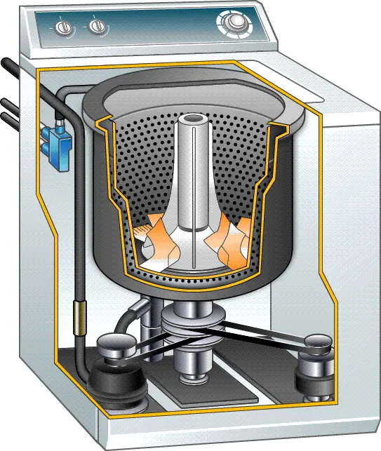
A washing machine (laundry machine, clothes washer, or washer) is a home appliance used to wash laundry. The term is mostly applied to machines that use water as opposed to dry cleaning (which uses alternative cleaning fluids and is performed by specialist businesses) or ultrasonic cleaners. The user adds laundry detergent, which is sold in liquid or powder form, to the wash water.
Washing machines can be classified as follows :
- Semi-automatic washing machine : The semi-automatic is needed for your assistant to get the job done. Here, you will have to pour in the water manually and need to set up the timer, etc.
- Fully automatic washing machine : The fully automatic washing machines are more convenient and offer a great range of functionality. You get fully automatic functions that carry out the washing without any manual interference. They are a little more budget friendly, and you spend a normal price to get actually purchase.
GEAR SHIFT :
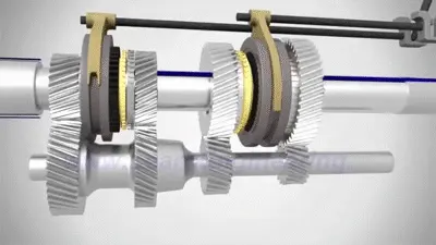
Gears are used for transmitting power from one part of a machine to another. In a bicycle, for example, it's gears (with the help of a chain) that take power from the pedals to the back wheel. Similarly, in a car, gears transmit power from the crankshaft (the rotating axle that takes power from the engine) to the driveshaft running under the car that ultimately powers the wheels. Changing gears is about using the engine's power in different ways to match changing driving conditions. The driver uses the gearshift to make the engine generate more force or more speed depending on whether hill-climbing power, acceleration from a standstill, or pure speed is needed. In practice, changing gears means meshing different sized gear wheels together, but you can't do that while the gearbox is transmitting power from the engine at high speed. That's why you need to press a car's clutch pedal before changing gears, which disengages the engine's input from the gearbox. You can then use the gearshift to change to a different pattern of gears, before letting the clutch transmit power back from the engine to the gearbox (and the wheels) once again.
OBJECTIVE :
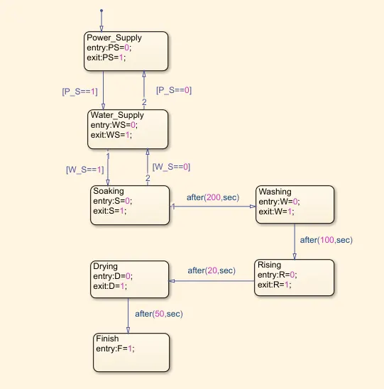
1. Implement control logic of a “Washing Machine” using Stateflow as per given sequence :-
- If the power supply is available, the system gets activated.
- If the Water supply is not available, stop the process & indicate through LED.
- Soaking time should be 200s followed by Washing time of 100s.
- Then rinsing happens for next 20s & dryer runs for 50s.
- After all the processes have completed turn on the finished LED.
2. Make a Simulink chart for the “Gear shift” logic as per below conditions :-
| Speed Range(kmph) | Gear |
| 0 to 15 | 1 |
| 16 to 25 | 2 |
| 26 to 40 | 3 |
| 41 to 60 | 4 |
| Above 61 | 5 |
- Give speed input while the simulation is running & display the gear number.
SIMULINK MODEL FOR WASHING MACHINE USING STATEFLOW :
SIMULINK BLOCK EXPLANATION :
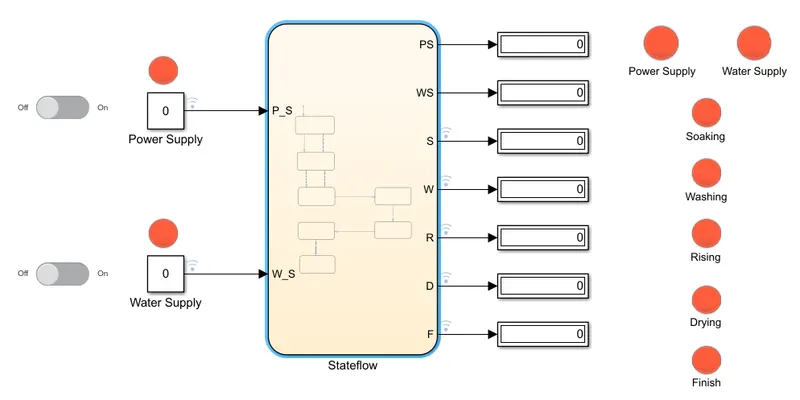
- Here, as we can see two slider switches and lamps are provided and connected with specific model parameters.
- One switch is connected to the constant block linked with the input data Power Supply which is responsible to turn ON (1) and OFF (0) the electric supply. Another one is connected with the constant linked with Water Supply which is responsible for water flow.
- Lamps displays two colours, Red indicates 'OFF condition' in the case of Power, 'No water flow' in the case of Flow and 'Process Incomplete' in the case of Finish lamp. Green indicates 'ON condition', 'Water Flow' and 'Process Complete' in the case of Power, Flow and Finsh lamps respectively.
STATEFLOW CONTROL PROCESS :
- First, we open a simulink stateflow chart in the simulink environment. Then in the chart we first provide the input power supply and water supply as a flow chart. In the below image if input power and water is ==1 there is zero input or no input. If the input power and water supply are ==0 then there in an input porvided for running the washine machine.
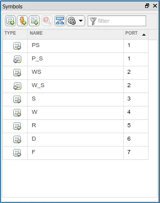
SYMBOLS PANE :
- After finishing the process of the flow chart we name the input and output varaibles according to the order of process using
the symbol pane which is situated under the prepare toolstrip.
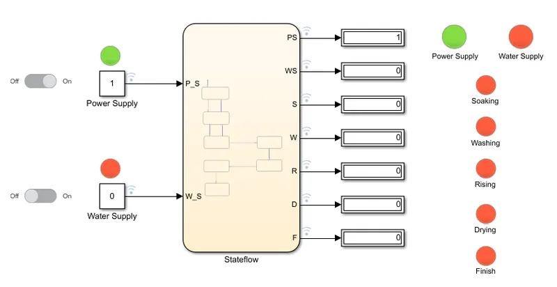
FOR THE ABOVE BLOCK REPRESENTATION OUTPUTS WOULD BE SHOWN BELOW :
OUTPUT DISPLAY WHEN POWER SUPPLY - ON, WATER SUPPLY - OFF :
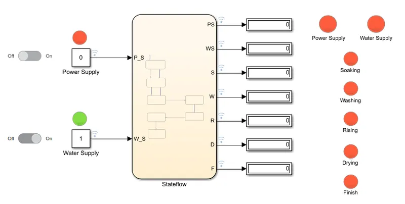
OUTPUT DISPLAY WHEN POWER SUPPLY - OFF, WATER SUPPLY - ON :
OUTPUT DISPLAY WHEN POWER SUPPLY - ON, WATER SUPPLY - ON :
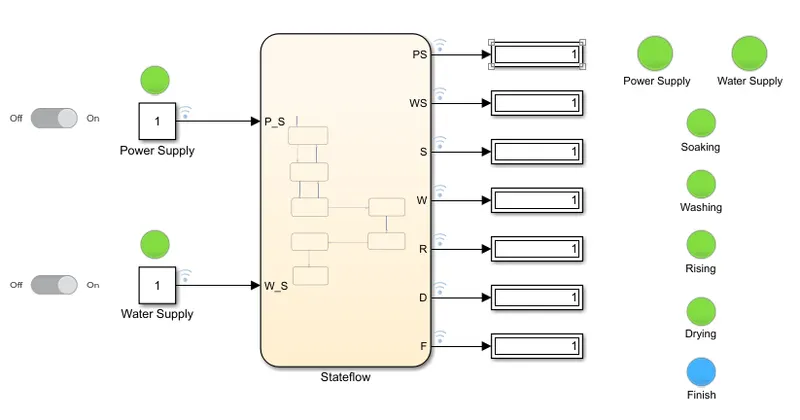
- The two inputs are given for the power and water supply. Once the inputs are given outputs are displayed by the flow chart as per the given sequence. The system are observed for sometime then it is checked and the process is completed by green light as displayed.
CONCLUSION : The washing machine logic is successfully implemented and executed.
SIMULINK MODEL FOR GEAR SHIFT USING STATEFLOW :
SIMULINK BLOCK EXPLANATION :
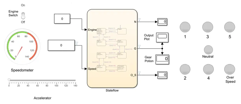
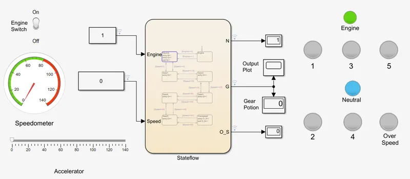
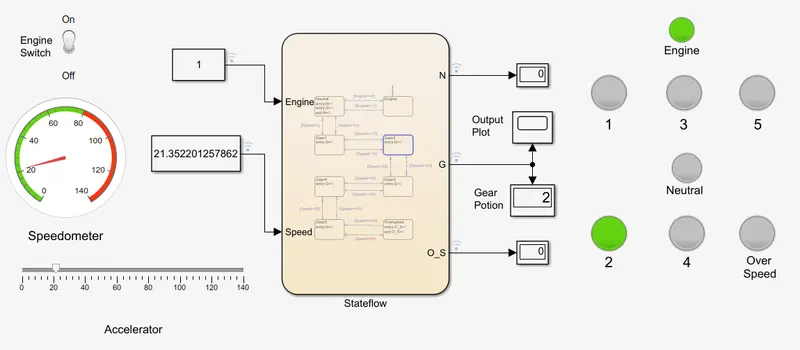
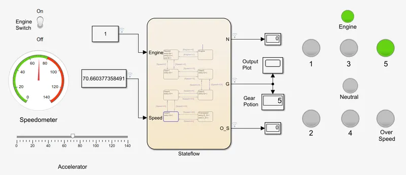
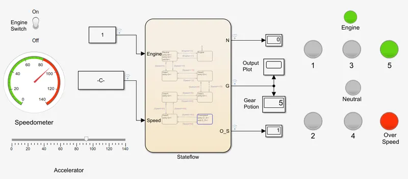
- In this Gear shifting case, we need to provide a continuous variable value for the input as a speed, for that, I use a Slider block as an accelerator for the speed change.
- As per our Requirement, we need to display the gear number to be visible on the Display block at the time of acceleration, so I use infinite time(inf) for compilation and change the speed manually on the Slider block.
- I configure the slider block by providing the values min=0 max=140, as the speed pf the vehicle Same values I configure to the Gaude block (speedometer), to show the input.
- I use Lamp block to show if the Engine is on or off and for the Overspeed.
STATEFLOW CONTROL PROCESS :
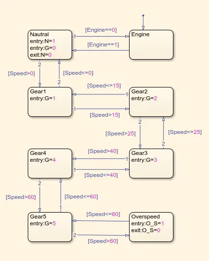
- In the question they have given the speed range in kmph for a particular gear.
- We are first creating a simulink stateflow chart for the gear shifting as per variation in speed. In the below image, we see that
we are providing varing input as speed and the gear number assigned for a particular speed range if the speed of the vehicle
is greater than the earlier gear's speed range the gear is changed.
SYMBOLS PANE :
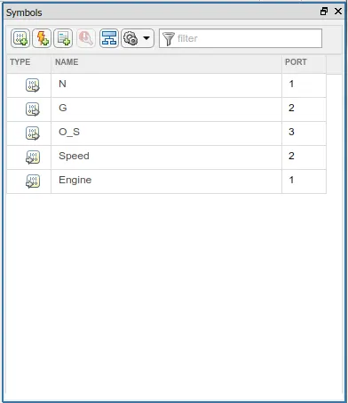
- Here, we provide the inputs which is the speed varing and outputs which is the gear number using the symbols pane in
prepare toolstrip.
FOR THE ABOVE BLOCK REPRESENTATION OUTPUTS DISPLAYS WOULD BE SHOWN BELOW :
Model showing Engine On State and Neutral Position is speed range 0 :
Model showing Gear 2 is speed range 16 to 25 :
Model showing Gear 5 is speed range Above 61 :
Model showing Gear 5 is speed range Above61 and Overspeed condition :
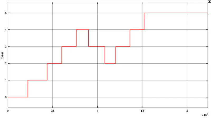
OUTPUT GEAR PLOT :
CONCLUSION: Hence, the given problem was simulated for the gear shift mechanism and executing the
Stateflow as per according to given conditions.