To Study the Multi-cell Battery Pack.
AIM : To Study the Multi-cell Battery Pack.
Battery Pack :
A battery pack is a set of any number of (preferably) identical batteries or individual battery cells. They may be configured in a series, parallel, or a mixture of both to deliver the desired voltage, capacity, or power density. The term battery pack is often used in reference to cordless tools, radio-controlled hobby toys, and battery electric vehicles.
Components of battery packs include the individual batteries or cells, and the interconnects which provide electrical conductivity between them. Rechargeable battery packs often contain a temperature sensor, which the battery charger uses to detect the end of charging. Interconnects are also found in batteries as they are the part which connects each cell, though batteries are most often only arranged in series strings.
When a pack contains groups of cells in parallel there are differing wiring configurations which take into consideration the electrical balance of the circuit. Battery regulators are sometimes used to keep the voltage of each individual cell below its maximum value during charging so as to allow the weaker batteries to become fully charged, bringing the whole pack back into balance. Active balancing can also be performed by battery balancer devices which can shuttle energy from strong cells to weaker ones in real-time for better balance. A well-balanced pack lasts longer and delivers better performance.
For an inline package, cells are selected and stacked with solder in between them. The cells are pressed together and a current pulse generates heat to solder them together and to weld all connections internal to the cell.
OBJECTIVES :
-
How weakest cell limits the usable capacity of the battery pack?
-
Explain the cell balancing techniques with relevant figures.
STUDY - 1 :
The weakest cell limits the usable capacity of the battery pack :
Battery Configuration -
The battery configuration in series or parallel connection can have a different voltage on each cell. The weakest cell in the battery pack could have more stress than other cells so that it will become the fastest damaged. This research will find the weakest cell in the battery pack. The identification of the weakest cell is performed on the charging and discharging process with direct measurement. The result shows that the weakest cell is located in the middle of the battery pack. The weakest cell has 2.75 V and the health battery cell have 2.9 V.
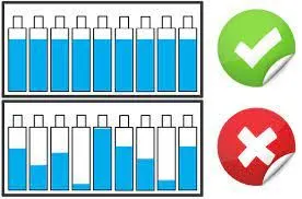
The weakest cell may affect the battery pack by the following condition -
- It will carry out a limit on the complete operation of the battery pack.
- Due to the weakest cell reaching the limit earlier than others, the battery pack may be underutilized.
- During the weakest cell condition, it is important to protect an individual cell overvoltage under voltage limits apply to all series-connected cells.
- It imposes a limit on the overall operation battery pack.
Problem with a Weak Cell in Battery Pack -
Mainly there are two prime mismatches which affects the overall output of the battery pack and they are -
- State of Charge(SoC) Mismatch
- Capacity/ Energy(C/E) Mismatch
- Each problem limits the pack capacity(mAh) to the capacity of the weakest cell and it is important to recognize.
- This type of cell to cell variation is more likely occurs in Li-ion prismatic cells, due to more extreme mechanical stresses.
- However weak cells (ones with lower capacity/ higher internal impedance) tend to exhibit higher voltage than the rest of the series cells at full charge termination. These cells are then weakened further by continuous overcharge cycles.
- On the discharge side, the weak cells tend to have lower voltage than the other cells, due to either higher internal resistance, or a faster rate of discharge than the result from the lower capacity.
- If the cells are overheated or overcharged, they are prone to accelerated cell degradation. They can catch fire or even explode as a thermal runaway condition can occur if a lithium-ion cell voltage exceeds 4.2V by even a few hundred millivolts.
Consider a lower voltage cell connected in a Series Configuration -
A battery pack in which “cell 3” produces only 2.8V instead of the full nominal 3.6V. With depressed operating voltage, this battery reaches the end-of-discharge point sooner than a normal pack. The voltage collapses and the device turns off with a 'Low Battery' message.

Consider a lower capacity cell connected in a Parallel Configuration -
A cell that develops high resistance or opens is less critical in a parallel circuit than in a series configuration, but a failing cell will reduce the total load capacity. It’s like an engine only firing on three cylinders instead of on all four.
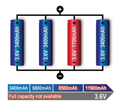
A weak cell will not affect the voltage but provide a low runtime due to reduced capacity. A shorted cell could cause excessive heat and become a fire hazard. On larger packs, a fuse prevents high current by isolating the cell.
STUDY - 2 :
Explaining the cell balancing techniques with relevant figures :
When a lithium battery pack is designed using multiple cells in series, it is very important to design the electronic features to continually balance the cell voltages. This is not only for the performance of the battery pack but also for optimal life cycles.
The use of cell balancing enables us to design a battery with a larger capacity for an application because balancing allows the battery to achieve a higher state of charge (SOC). A lot of companies choose not to use cell balancing at the start of their design to reduce cost but without the investment in the cell balancing hardware and software, the design does not allow the SOC to approach 100 percent.
Cell Imbalance -
If lithium cells are overheated or overcharged, they are prone to accelerated cell degradation. They can catch fire or even explode as a thermal runaway condition can occur if a lithium-ion cell voltage exceeds 4.2 V by even a few hundred millivolts.
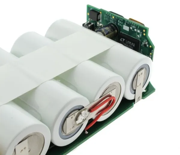
Every pack that we design and manufacture at Epec has an overvoltage protection circuit (sometimes even a backup) to go along with standard cell balancing that will prevent such an event from ever occurring. In a multi-cell battery pack, which is commonly used in laptop computers and medical equipment, placing cells in series opens up the possibility of cell imbalance, a slower but persistent degradation of the battery.
Cell Balancing -
Cell balancing is the process of equalizing the voltages and state of charge among the cells when they are at a full charge. No two cells are identical. There are always slight differences in the state of charge, self-discharge rate, capacity, impedance, and temperature characteristics. This is true even if the cells are the same model, same manufacturer, and same production lot. Manufacturers will sort cells by the similar voltage to match as close as possible, but there are still slight variations in the individual cells' impedance, capacity, and self-discharge rate that can eventually lead to a divergence in voltage over time.
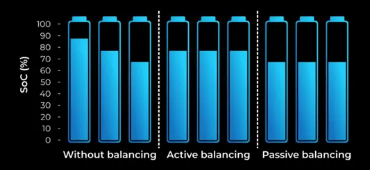
Most typical battery chargers detect full charge by checking whether the voltage of the entire string of cells has reached the voltage regulation point. Individual cell voltages can vary as long as they don’t exceed the limits for overvoltage protection. However, weak cells (ones with lower capacity / higher internal impedance) tend to exhibit higher voltage than the rest of the series cells at full charge termination. These cells are then weakened further by continuous overcharge cycles. The higher voltage of the weaker cells at charge completion causes accelerated capacity degradation. If the maximal recommended charging voltage is exceeded even by as little as 10 percent, it will cause the degradation rate to increase by 30 percent.
On the discharge side, the weak cells tend to have lower voltage than the other cells, due to either higher internal resistance, or a faster rate of discharge that results from the lower capacity. This means that if any of the weak cells hit the cell under-voltage protection limit while the pack voltage is still sufficient to power the system, the full capacity of the battery will never be used as the pack protector will prevent over-discharge (which would damage the cell) by stopping the discharge of the whole pack when one cell voltage goes below the cell under-voltage threshold (usually around 2.7 V).
Cell Balancing Techniques -
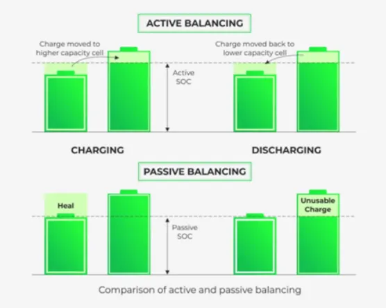
The fundamental solution of cell balancing equalizes the voltage and state of charge among the cells when they are at a fully charged state. Cell balancing is typically categorized in two types :
- Passive
- Active
Passive Cell Balancing -
The passive cell balancing method is somewhat simple and straightforward. Discharge the cells through a dissipative bypass route. This bypass can be either integrated or external to the integrated circuit (IC). Such an approach is favorable in low-cost system applications. The fact that 100% of the excess energy from a higher energy cell is dissipated as heat makes the passive method less preferable to use during discharge because of the obvious impact on battery run time.
Fixed Shunt Resistor Method -
The fixed shunt resistor cell balancing circuit is as shown in Figure be. Where, V1, V2, V3, V4, …Vn is each cell voltage which is connected in series, and R1, R2, R3, R4, …Rn are fixed shunt resistors of each battery cell.
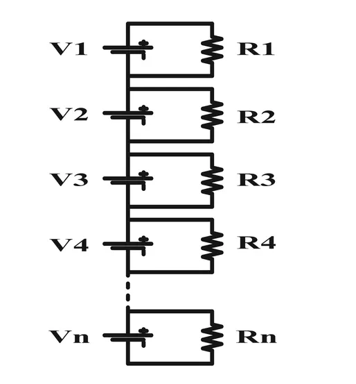
This technique balances each cell voltage by connecting the fixed resistor in parallel with each series connected cell based on the required cell balance current. The balancing current is dissipated through the resistor which limits the voltage of each cell.
This method is suitable for nickel and lead-acid batteries balancing circuit, since these batteries are brought into overcharge conditions without any damage. This circuit is very simple, hence it requires less number of components and low cost. But the disadvantage of this technique is to provide the energy losses due to the energy are dissipated as heat in all the cells during balancing operation.
Switching Shunt Resistor Method -
The switching shunt resistor cell balancing circuit is as shown in Figure below. Where, V1, V2, V3, V4, …Vn is each cell voltage which is connected in series, Q1, Q2, Q3, Q4, …Qn are semiconductor switches of each cell andR1, R2, R3, R4, …Rn are fixed shunt resistors of each battery cell.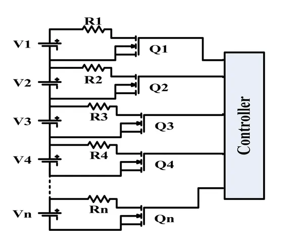
This technique balances each cell voltage by connecting the resistor in parallel with each series connected cell through controlled on/off semiconductor switches or relays. In this method, the resistor value is properly chooses based on the required balancing current. This method requires a controller for controlling the circuit in two different two modes. In continuous mode, the switches on/off are controlled at the same time, in sensing mode, the voltage of each cell is detected by a voltage sensor, which detects the cell imbalance situation and decides which resistor should be shunted.
This method is also called as charge shutting method and is commonly used for Li-ion batteries balancing circuit. This circuit is more reliable than a fixed shunt resistor balancing circuit. Also, this technique is providing the energy losses due to the higher currents are flowing through the switches and resistors during balancing operation.
Active Cell Balancing -
Active cell balancing, which utilizes capacitive or inductive charge shuttling to transfer charge between battery cells, is significantly more efficient because energy is transferred to where it is needed instead of being bled off. Of course, the trade-off for this improved efficiency is the need for additional components at a higher cost.
Capacitor Based Active Balancing Method -
This technique is known as charge shuttling method in which charge from the higher energy cell is released, that charge must be stored in capacitor, and then transfer into lower energy cell. There are different topologies of capacitor-based cell balancing schemes are available and shown in Figure below. This technique can be classified based on a single capacitor and several capacitors used equalization methods.
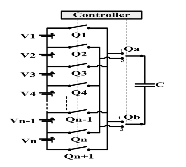
The single capacitor cell equalizing circuit is shown in Figure above. Where, V1, V2, V3, V4, …Vn is voltage of each cell which is connected in series, Q1, Q2, Q3, Q4, …Qn, Qn + 1, Qa, Qb are semiconductor switches and C is a single capacitor.
This balancing circuit requires n + 5 semiconductor switches and only one capacitor for equalizing the n number of cells charge levels. The basic principle of this circuit is equalizing the charge of each cell by charge or discharge of common balancer such as a capacitor which transfers the energy between any two cells in a battery string. For example, when Q1, Qa(1), Qb(2), and Q2 are turned ON, and others are turned OFF, the capacitor C is connected in parallel with Cell V1. When Q3, Qa(1), Qb(2), and Q4 is turned ON, and others are turned OFF, the capacitor C is connected in parallel with cell V3. Hence, the energy moved straightforwardly between any two cells at any position in the battery pack with this method.
This method is also known as direct cell to cell method and suitable for high power applications. It is very simple due to only one capacitor is used to balancing the overall battery pack. But, it has a slow balancing speed and requires a number of semiconductor switches and intelligent control techniques for controlling switches.
Inductor Based Active Balancing Schemes -
There are different topologies of inductor-based cell balancing schemes are available and shown in Figure below. This technique can be classified based on a single inductor and several inductors used equalization methods.

The single inductor cell equalizing circuit is shown in Figure above. Where, V1, V2, V3, V4, …Vn is voltage of each cell which is connected in series, Q1, Q2, Q3, Q4, …Qn, Qn+1, Qa, Qb are semiconductor switches and L is a single inductor. The single inductor balancing method shares the same switching topology as the single capacitor balancing method. This balancing circuit requires two groups of n + 1 semiconductor switches (MOSFETs) and a diode is in series with each switch (MOSFET) to prevent the cell from the short circuits during equalizing operation, and only one inductor for equalizing the n number of cells charge levels. The basic principle of this circuit is equalize the charge of each cell by charge or discharge of common balancer such as an inductor that transfers the energy between any two cells in a battery string. Hence, the energy moved straightforwardly between any two cells at any position in the battery pack with this method.
This method is also known as a direct cell to cell method. It is very simple due to only one inductor is used to balancing the overall battery pack. It has a faster balancing speed than capacitor-based topology and higher efficiency. But it requires high implementation cost than capacitor balancing topology, a number of semiconductor switches, and intelligent control techniques for controlling switches.
CONCLUSION :
-
Successfully Explained How the weakest cell limits the usable capacity of the battery pack and the cell balancing techniques with relevant figures.
REFERENCES :
https://en.wikipedia.org/wiki/Battery_pack
https://onlinelibrary.wiley.com/doi/10.1002/est2.203
https://www.batterypoweronline.com/blogs/why-proper-cell-balancing-is-necessary-in-battery-packs/