Project 2
AIM:To route the Wiring harness on Given car body and to prepare flattening view drawing in CATIA V5. By applying of all the Packaging rules & Industry best practices.
OBJECTIVES:
- Need to identify the electrical components that are present in the backdoor and place the conncetors according to it.
- To Route the wiring harness for the Backdoor without fouling and check for bundle conncetivity
- Protect the wiring harness by using protective coverings like cot tubes ,tapes etc...
- To flatten the wiring harness that is made and prepare a dawing sheet of the flatten harness out of it.
INTRODUCTION:
WIRING HARNESS:A wiring harness is an organised set of wires,terminals & connectors that runs throughout the entire vehicle & transmit the information and electrical power thereby playing a cruical role in connecting a vareity of components.The wirng harness is a combination of both mechanical & electrical data.
WIRING HARNESS ROUTING:Wiring harness deals with the desired path of the wiring harness into given vehicle environment by applying set of design rules and industry best practises.
WIRING HARNESS PACKAGING:Wiring harness packaging deals with fixing/mounting strategy of wiring harness routing to ensure safe,reliable & durability of wiring harness.
DOOR WIRING HARNESS:
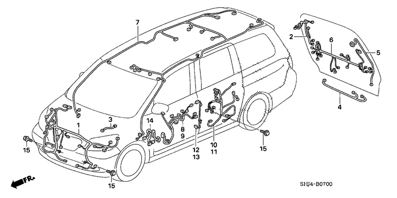
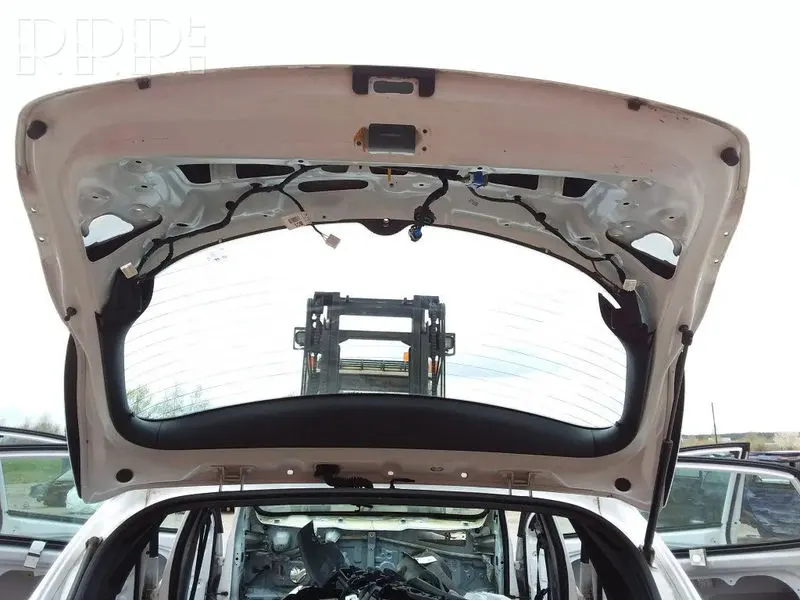
In the case of car doors, as the door of the automobiles opens and closes, the wires bend. If you use the car every day, the door will open and close many times. In case of Back door, the trunk could be open and close many times in daily life. Backdoor wiring harness mainly introduced to connect the brake lights, number plate lights, rear wiper motor, rere camera sensor & defogger connections. The harness routing should be maintained properly with all the supporting components like clips, clamps with proper protective covers, rubber grommets.
DESIGN METHODOLOGY:
Step_01:Identify the harness assembly componets.
There are many electrical devices in a car backdoor like Rear lamps, Head stop lamp, Rear camera , Number plate light, wiper motor, gas stay etc... We have to identify componets to route beteween this devices.
For this Backdoor i have considered the following conncetors & Clips:
- Inter connection Connector (C-776438-1) – 1
- Top mounted stop light,Rear camera &Number plate light connections (C-282080-1) – 3
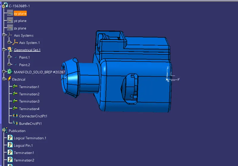
- Brake Light Assembly Connections & Wiper motor conncetion (C-1563689-1) – 3
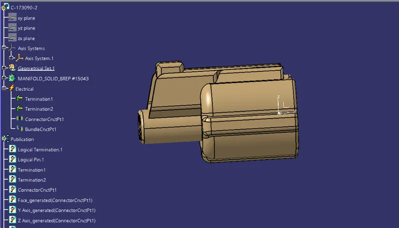
- Defogger conncetion (C-173090-1) -2
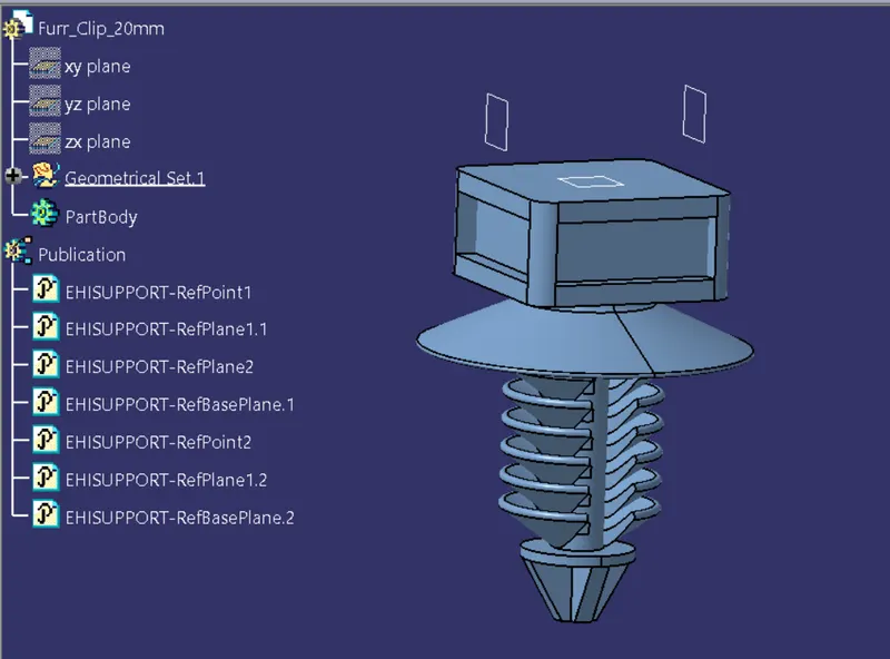
- Furr tree clips -10
Step_02:Define all Harness components as electrical and these are the steps to be followed:
- First download the components that are required from the given source.
- Provide the required geometrical parameters like points,axis system.
- The points are to be created by using point>>between command at the bundle entry point and the connector connection point.
- Create an axis system at the connector connection point.
- Now Switch to Electric Part Design and define the part as connector in catia v5, give no. of terminations according to the conncetor type.
- Define Bundle connection point.
- Define connector connection point.
Similarly we need to use Furr tree clips in between the conncetors to ensure smooth bundle routing.So we also need to define the Furr tree clip electrically.Steps to be followed:
- After downloading the part file,create 2 points for the bundle entry & exit, by point>>center/sphere method.
- Create planes at that 2 points by using parallel through points and then base plane by using offset method.
- Now switch to Electrical part design.
- We need to define the part as support part for that,
- Click on "Define support part ">> select part >> select entry point, select entry plane,exit plane, and base plane.
- Again Click on "Define support part ">>select part >>select exit point ,select exit plane and base plane as the second plane is automatically taken.
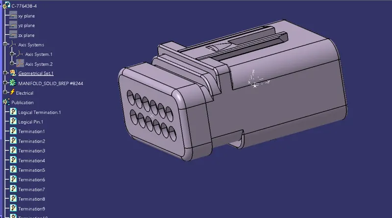
Connector C-776438 is used as interconnection conncetor. Number of poles in interconnection decided by number electrical devices going to connect in that wiring Harness.
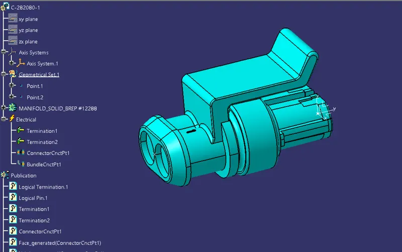
Conncetor C-282080 is used for rear camera RCA cable which consists of 2 wires So two way connectors is used here .Same connetor is used for number plate light and rear head stop light connections.
Connector C-1563689 is used for rear head lamps connections with 3 terminal is must needed and it is also used for wiper motor conncetion.
Conncetor C-173090 is use for Defogger conncetion at both sides(LH & RH ).
Furr tree clips
Step_03:Preparing Harness Assembly
Creating the context assembly for the BackDoor Harness Assembly.
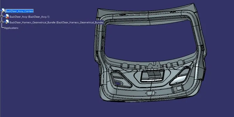
For creating the context assembly Goto>>File>>New>>Product. Context assembly is nothing but the product file which contains the BackDoor 3D-CAD data and the Backdoor wiring harness geometrical bundle.
- The first product file Containing the BackDoor CAD data.
- The second product file named as Geometrical bundle since it contains all the information about the connectors and other mounting equipments like clips and clamps which are electrically defined for the assembly & the Mutli branchable data.The Geometrical bundle is to be defined electrically,for that switch to "Electrical Harness Assembly" workbench and deifne it by using "Define Geometrical bundle" command before adding the files.
Step_04:Now we need to plcae the conncetors according to the respective positions by using the manipulations,smart move & compass.
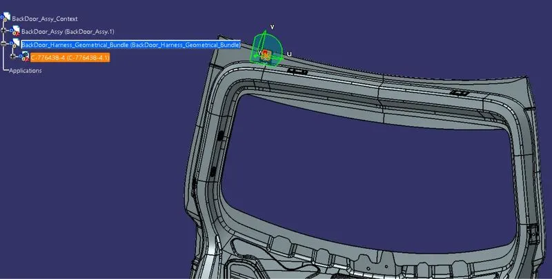
- Interconnection conncetor is palced in Top left side of the back door. From where the harness routing is going to start.
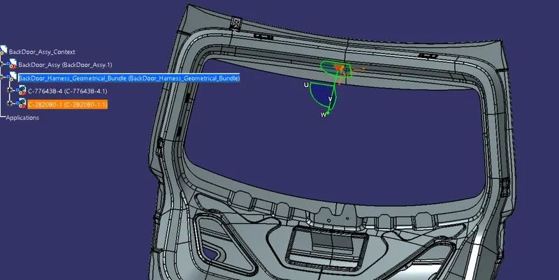
- Rear head stop light conncetion along with Rear camera sensor,number plate light conncetion conncetors are placed at their desired positions.
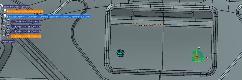
- Wiper motor connection and Rear tail lamps conncetions conncetors are placed at their positions.
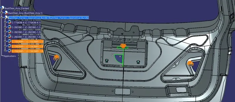
- For defogger conncetion a conncetor is placed on both sides ( LH & RH).
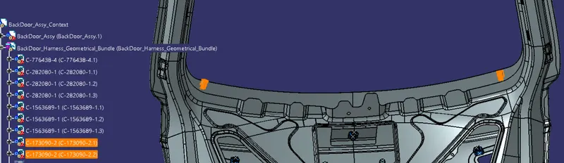
- Now placing of furr tree clips between the concnetors.
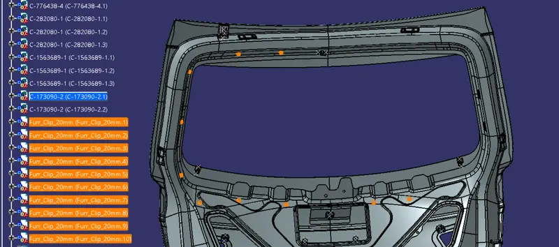
- The Conncetors along with the furr tree clips are placed in their positons.
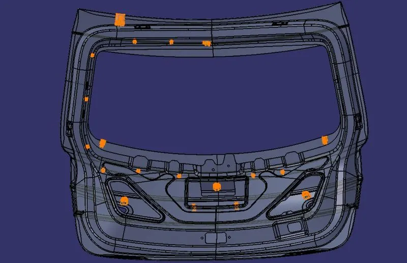
Step_05:Routing the Bundle.
Some important packaging rules and best practices to be considered during the wiring harness routing and placing of the clips and clamps are as follows –
- Branch length should be minimum 50mm.
- Minimum distance between clip and nearest branching point should be 25mm.
- The minimum distance between two breakout points should be 50mm.
- Limit the number of branches from single branching point to 4.
- Wiring harness routing shall provide ease in manufacturing,accessibility,easy removal and easy maintainance of attached equipment and wiring harness.
- Routing through small structural holes and openings shall be avoided,to minimize chaffing and handling of the wiring harness during installation.
- Routing shall provide enough slack for each branch to avoid adiitional stress on wires and to avoid fouling.
- Avoid routing harness over the bolts,Near to the bolted joits or scrwed joints.it may damnage harness or May puncture the harness.
- Keep the harness away from the panel mounting screws or bolts.
- Avoid routing wiring harness near the exhaust manifold and its components and also from other unshielded heat sources. If the routing is not possible then maintain a minimum distance of 200mm.
- Enough clamps shall be provided to ensure positive clearance with surroundings and safety of wiring harness.
- Distance between two clmaps on a straight branch should be maximum 200mm.
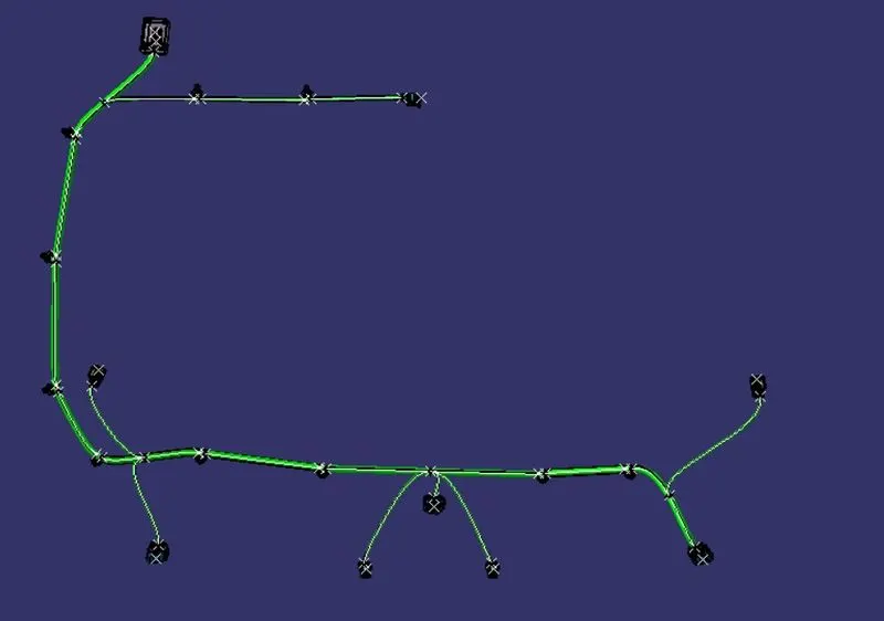
Keeping all the above packaging rules we can start the routing of the wire and provide clipping and clamping wherever necessary during the routing process.
- Main branch-10mm
- sub branches-5mm
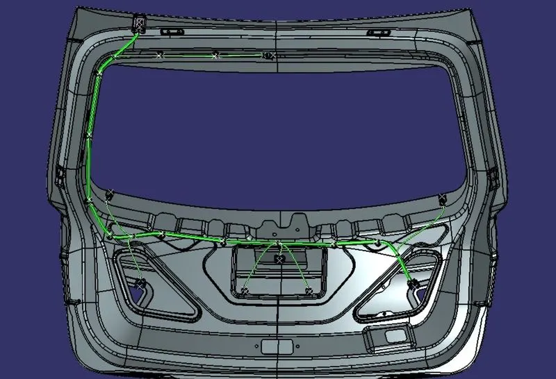
Step_06:BUNDLE CONNECTIVITY CHECK
For proper flattening of the bundle in Bundle flattening assembly, we need to ensure that the bundle created is fully connceted.
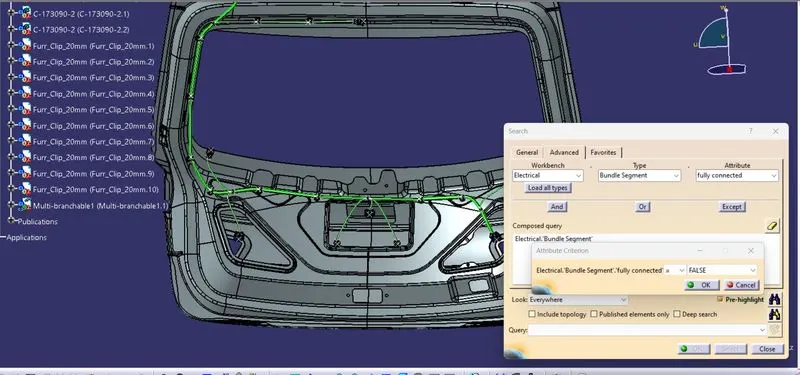
- Activate the Mutli Branchable Document >> Goto Edit >> Search >>Advanced
- Set the Attribute creation to "Flase" since it is easy to check the bundles that are not fully connceted.
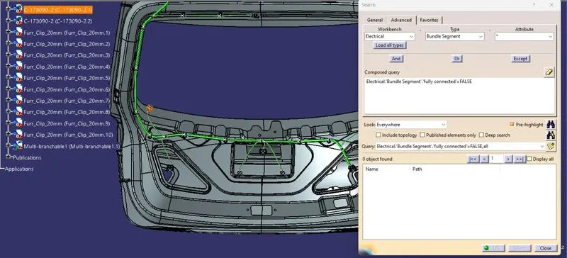
As we can see that there are no elements visible in the dialog box since all the branches are fully connceted.
Step_07 : Adding protection coverings
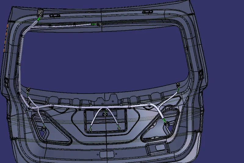
Here corragared tubes(Cot tubes) are used as protection cover of bundle segment.
In corrgated tubes Start and End extremity have to set 30 mm from connector.Since the main branch is 10mm i have provided a 15mm Cot tube over it similarly the sub branch is 5mm so it is provided with 10mm cot tubes.
Step_08:WIRING HARNESS FLATTENING
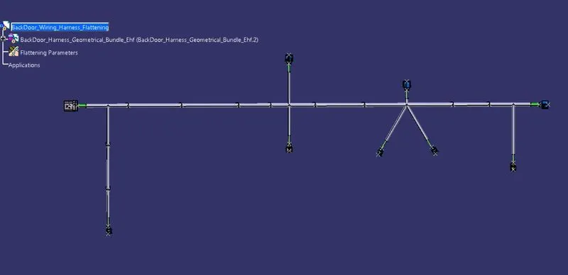
Now we need to convert the geometrical bundle into a flattened wiring harness in the "Electrical Harness Flattening" Workbench.
- To create the Flattened Harness, we need to create a new product file and switch into the Electrical Harness Flattening workbench.
-
Select the 'Extract' option from the "Electrical Harness flattening workbench" and select the Geometrical bundle product in the wire harness assembly product file.Then wire harness assembly is imported to the Wire flattening product file with '_EHF' extension added to the geometric bundle assembly name & by using flatten command make the bundle flat.
Step_09: FLATTENED HARNESS VIEW IN THE DRAWING SHEET
Now we need to create a drawing file for the flatten part,for that create a new drawing file and by using the front view option select the view of the bundle and adjust it according to the sheet and make neccessary settings for that.
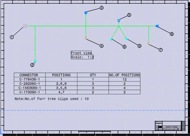
CONLUSION:Routing of wiring harness on Backdoor is done and flatten view on 2D diagram prepared using CATIA V5 by applying all packaging rules and industry best practice.