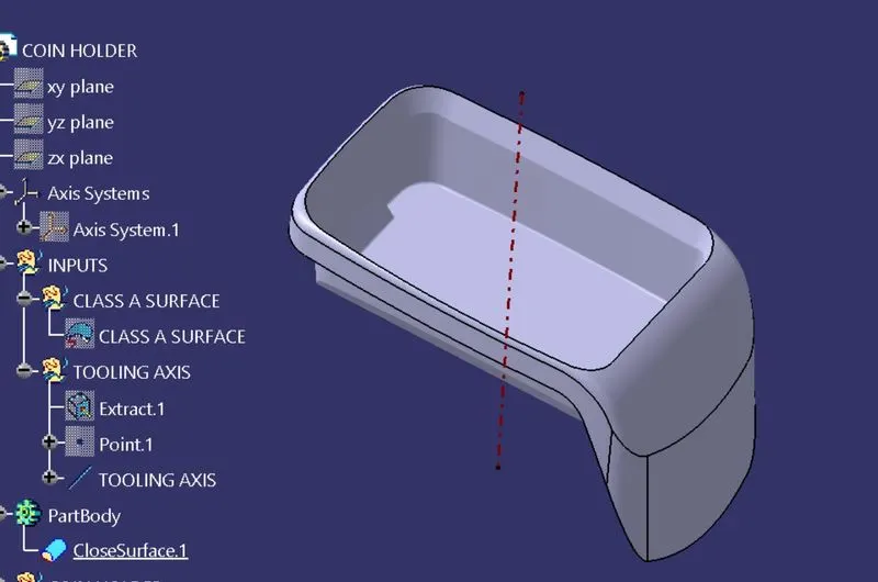
Coin Holder Design
The given CLASS A ASURFACE is to be checked properly,for making sure the given surface has no gaps.Once if it confromed ,then go for tooling axis creation.
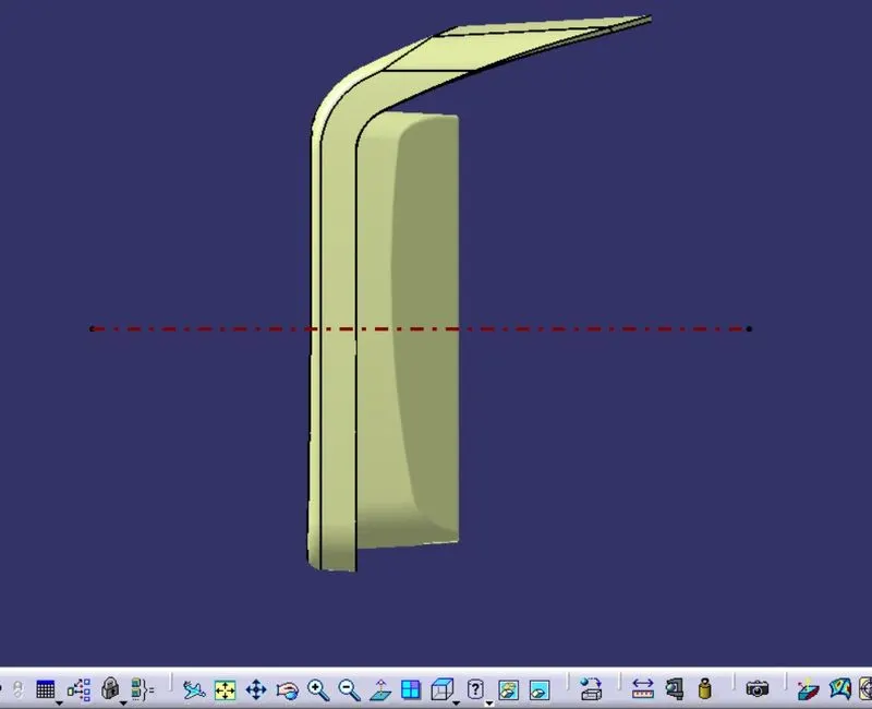
TOOLING AXIS: check the given surface completely to identify the location of tooling axis,always select the surfsce which is flat and when viewing from the normal view ensure all the surface can be completed with that view.In this case the base is the possible way to select for tooling axis.Extract the base surface and create a point and make a line w.r.t to that point.This line is known as Tooling axis line.Highlighte the line with properties.The tooling axis with normal view is shown in the fig.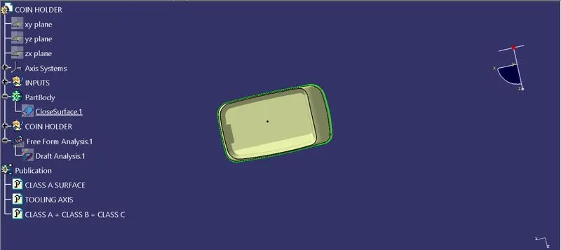
DRAFT ANALYSIS: Once the tooling axis is completed then we can proceed with the draft analysis of the given surface.For that open Feature draft analysis and select modes to set proper mode options which shows 3 colors(blue, red,green).The green is preferable and set the draft angle to 3 deg.Then goto display option and click on analsyis under running point and check the angles on all thesides os the surface,and goto direction option selection compass and drag it into the tooling axis and fit in it such that the w face should coincide with the tooling axis.If the surface is in blue color change it to green by using flip option in the directions.The initial draft analysis of given surface is shown below.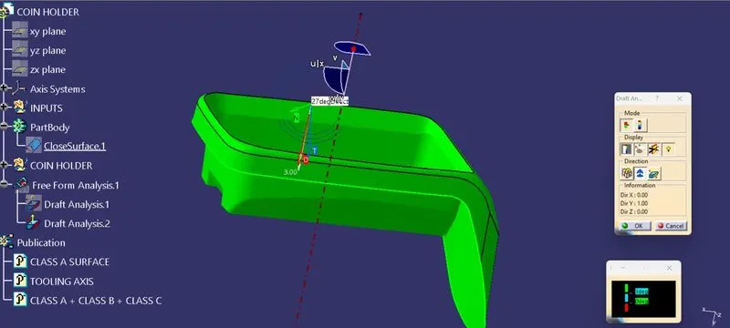
The final draft analysis os the CLASS A + CLASS B +CLASS C is shown below.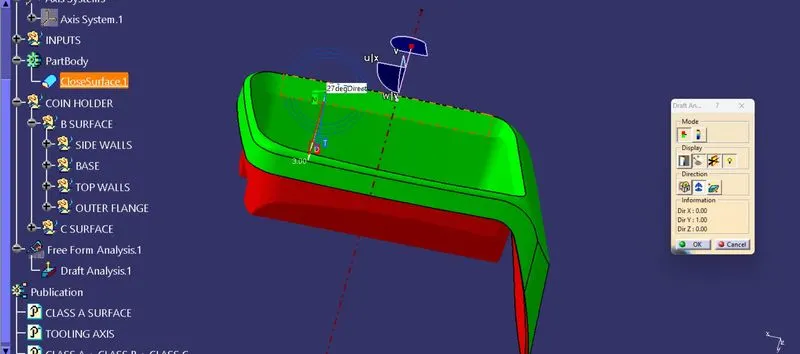
B SURFACE CREATION: For creating the B surface extract the base,side walls,top walls and outer flanges.untrim the each components and extrapolate them.After extrapolation trim and offset the each separte components to the given thickness of 2.5 mm.The outer flange is bit more complicated and it has to be extracted into two sub components and then extrapolate them and then trim the components to get the final CLASS B SURFACE.The final CLASSS B SURFACE is shown below.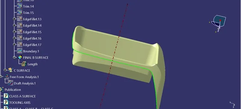
C SURFACE CREATION: Oce the B surface is created we need to create the C surafce.To create the C Surface we need to extract the class A surface using multiple extract command.The boundary of the class A is extracted once and then the outer flange is also to be extracted.By using sweep command,goto with reference surface selecting the boundary extract along with the outer flange and give the angle to 90 deg as we need to cretae the c surface perpendicular to the outer flange.Give the minimum thickness of 4 mm and click on ok.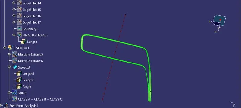
The B surface and C surface are to be trimmed.the final output is to be joined with the CLass A surface.The final CLASS A + CLASS B + CLASS C is shown below in different views.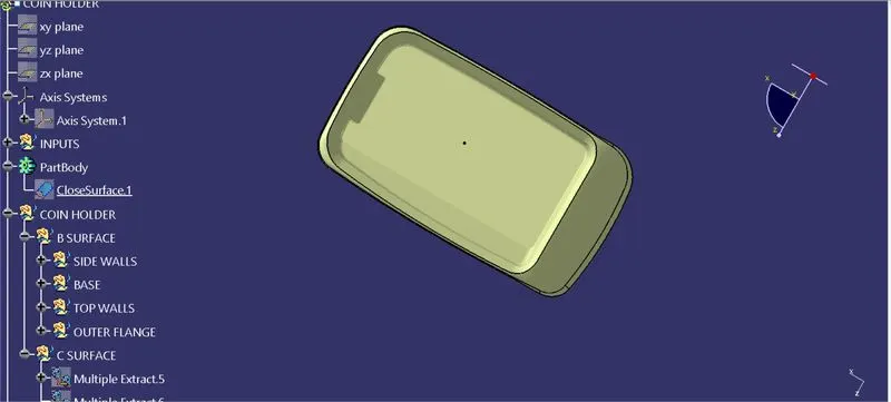
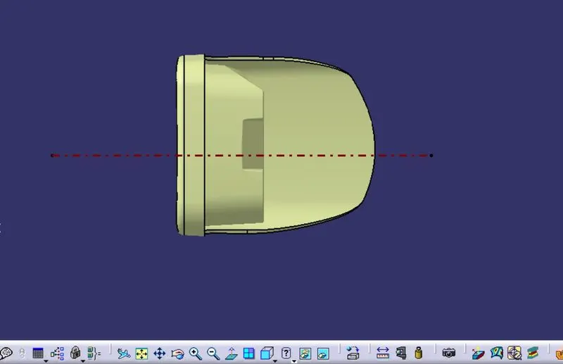
Once the surface is completed then goto mechanical design>>part design create a part body and close the surface by suing close surface command.