Wiring Harness on 16V Engine
AIM:
To design and develop the Wiring harness on Given 16V Engine and Prepare flatten view drawing in CATIA V5. Application of all Packaging rules, Industry best practices studied in this course shall be demonstrated in design.
OBJECTIVE:
The objective of the project is to route the wiring harness on given V16 Engine and prepare flatten view drawing in CATIA V5. All types of packaging rules have to be considered while routing the harness.All the mechnical comoponents are to be defined electrically. Also, Industry best practices should be demonstrated in this design. All the necessary details like clearance, clipping/clamping selection, harness fixing requirements, harness continuity should be provided in order to design wiring harness.Need to provide additional slack % of 5-10mm if required.In order to flattening the bundle is to be fully connceted.
INTRODUCTION:
A wiring harness is an organised set of wires,terminals & connectors that runs throughout the entire vehicle & transmit the information and electrical power thereby playing a cruical role in connecting a vareity of components.The wirng harness is a combination of both mechanical & electrical data.
WIRING HARNESS ROUTING:The best design for wiring harness routing is the distance we need to keep the wiring harness from the different components of the vehicle system such as exhaust,coolant lines,heater lines etc..
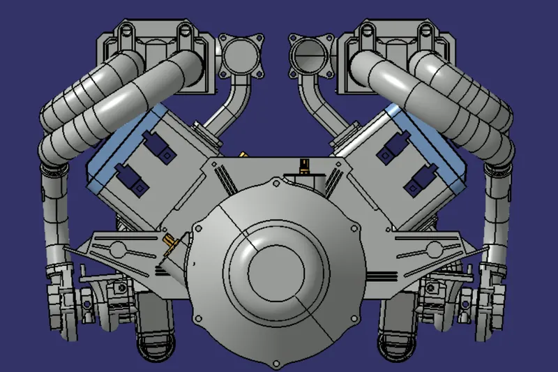
DESIGN METHODOLOGY:
Step_01:Download the given 16V engine CAD data and required connectors,clips,clamps CAD data from the given source.
Step_02:Defining the mechanical component into electrical component(Conncetors) these are the stes to be followed:
- First download the components that are required from the given source.
- Provide the required geometrical parameters like points,axis system.
- The points are to be created by using point>>between command at the bundle entry point and the connector connection point.
- Create an axis system at the connector connection point.
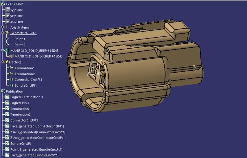
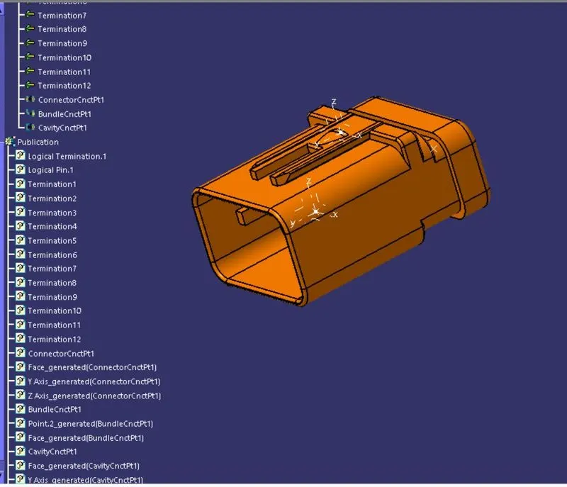
- Now Switch to Electric Part Design and define the part as connector in catia v5, give no. of terminations according to the conncetor type.
- Define Bundle connection point.
- Define connector connection point.
The conncetors that are used for this 16V Engine are:
- 4 pole connector(c-1563689-1)
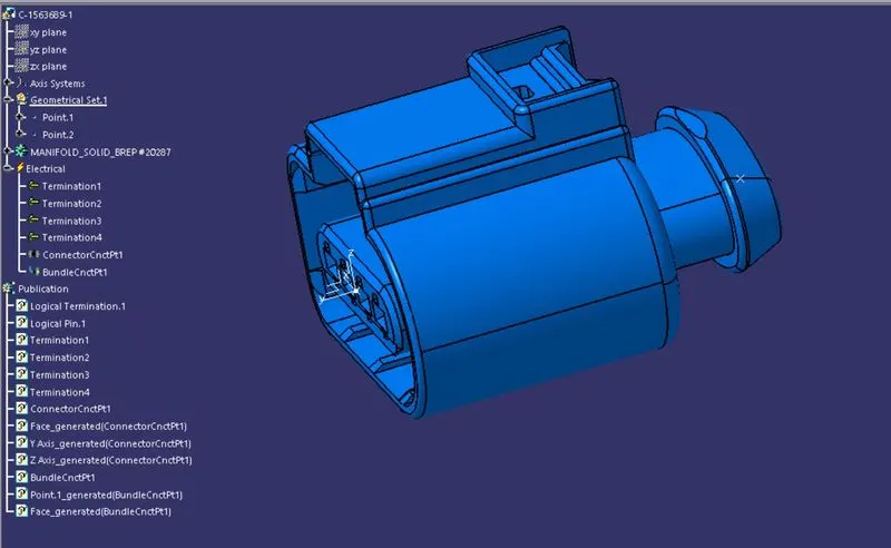
- 2 pole connector(C-282080-1)
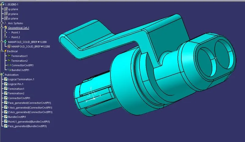
- 2 pole connector
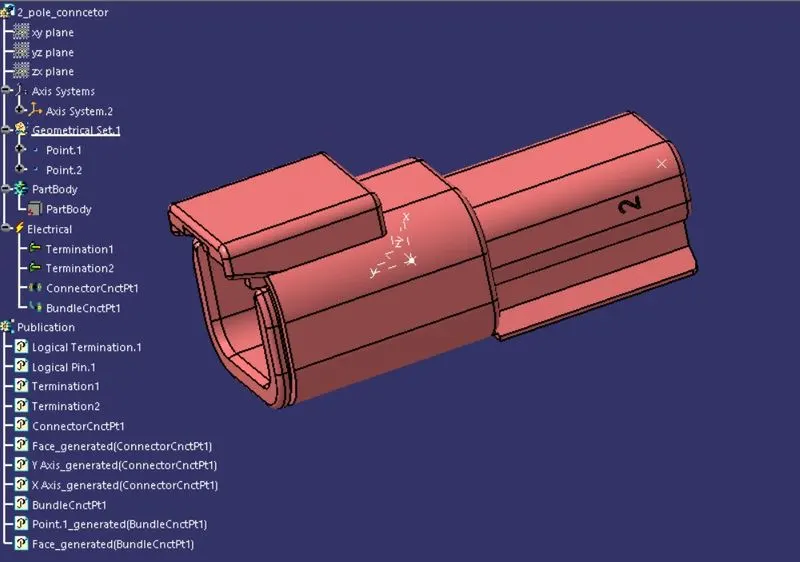
- 2-pole connector (C-173090-2)
-
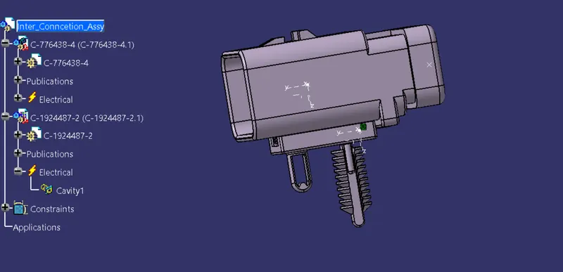
Inter Connection Connector (C-776438-4)
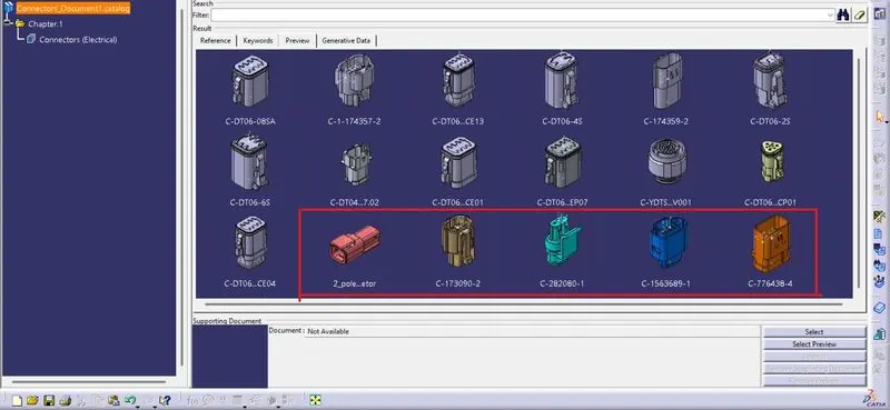
Step_03: Once the conncetors are electriclly defined add them into a catalogue containing other connectors for grouping them as a famliy.
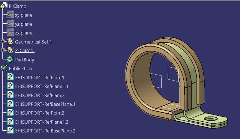
Step_04:Definng the P clamps,furr tree clips,L Clamp & cavity clip electrically.
- After downloading the part file,create 2 points for the bundle entry & exit, by point>>center/sphere method.
- Create planes at that 2 points by using parallel through points and then base plane by using offset method.
- Now switch to Electrical part design.
- We need to define the part as support part for that,
- Click on "Define support part ">> select part >> select entry point, select entry plane,exit plane, and base plane.
- Again Click on "Define support part ">>select part >>select exit point ,select exit plane and base plane as the second plane is automatically taken.
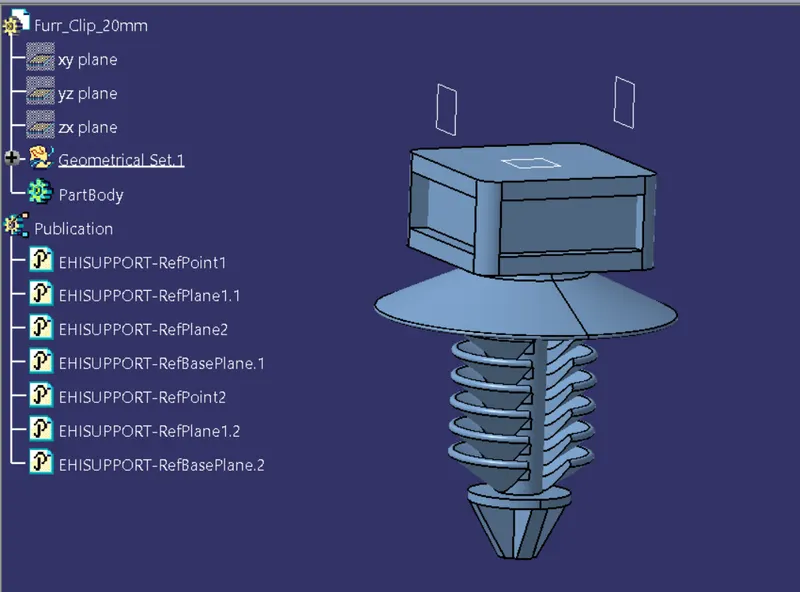
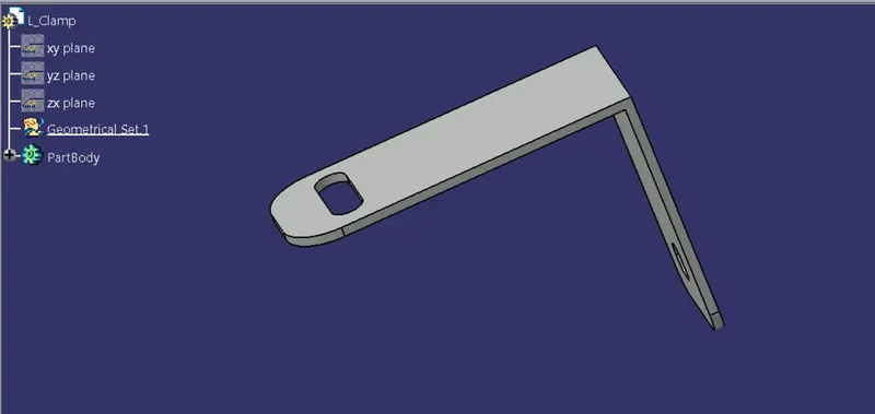
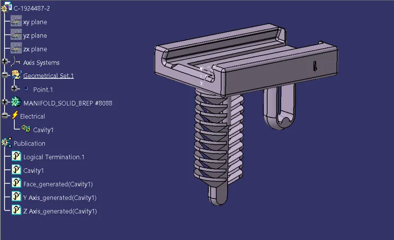
STEP_05:create new product file for the inter connection connector and cavity assembly.
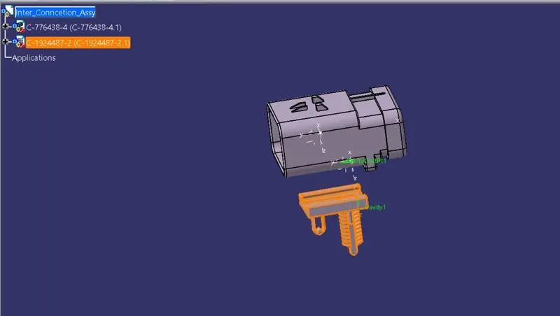
Step_06:Defining the Guiding channel electrically
- Create bundle entry point and exit point by point >> between option.
- Create a line curve between the entry and exit points for creating the multi-branchable using external curve inside the channel.
- Create 8 bundle entry points on the openings for connecting the injector connectors.
- Swtich of ELectrical part design & define the channel electrical using the "Define Mounting Equipment" option.
- Define bundle entry points by using the “Define Bundle Connection Point" option.
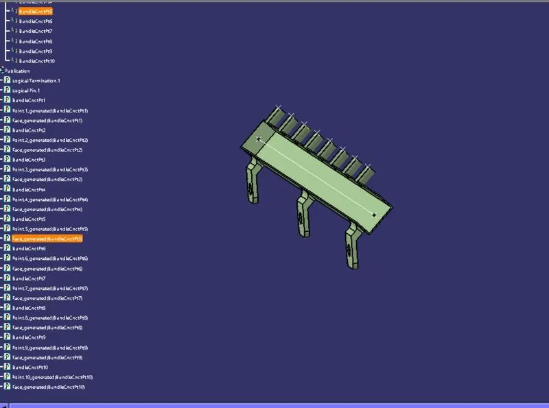
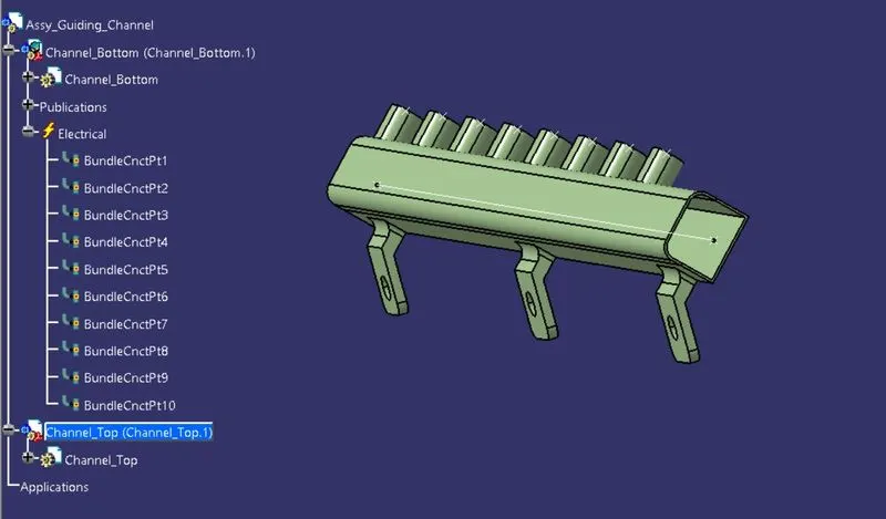
Then create a new product assembly with channel bottom and top part.
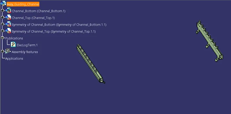
Create Channel symmetrical assembly and define the symmetry bottom channel electrically using define mounting equipment option and also create all the required geometrical parameters on it.For creating the symmentry Guiding channel use the original guiding channel adn symmetry command in the Assemby workbench.
Step_07:Creating the context assembly for the Engine Assembly.
For creating the context assembly Goto>>File>>New>>Product. Context assembly is nothing but the product file which contains the engine 3D-CAD data and the engine harness geometrical bundle.
- The first product file Containing the Engine CAD data.
- The second product file named as Geometrical bundle since it contains all the information about the connectors and other mounting equipments like clips and clamps which are electrically defined for the assembly & the Mutli branchable data.The Geometrical bundle is to be defined electrically,for that switch to "Electrical Harness Assembly" workbench and deifne it by using "Define Geometrical bundle" command before adding the files.
- The L-clamp is added in the main context assembly.
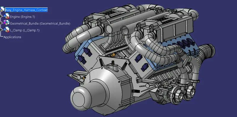
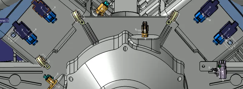
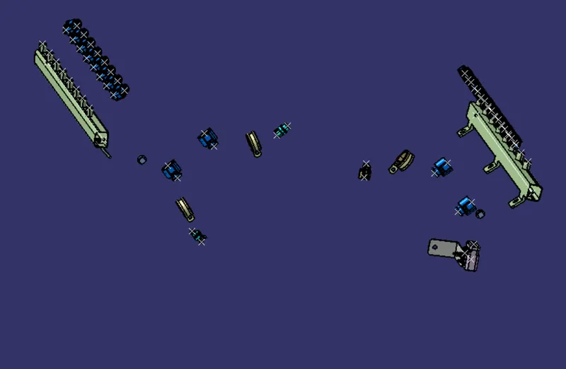
As we can see the given V16 engine 3D-CAD model requires a total of 24 Connectors to be placed on it in which one Inter Connection Connector for the engine wiring harness assembly. The connectors used in this engine are as follows
- 8 no.of connectors are required on the fuel injector sensors on each side of the cylinder head, i.e.; total 16 fuel injector sensor connectors are needed(8 on right side & 8 on the other side).
- Total 4 numbers of cam-shaft sensor connectors are needed.
- 1 Inter conncetion conncetor along with the cavity clip is placed on the L Clamp.
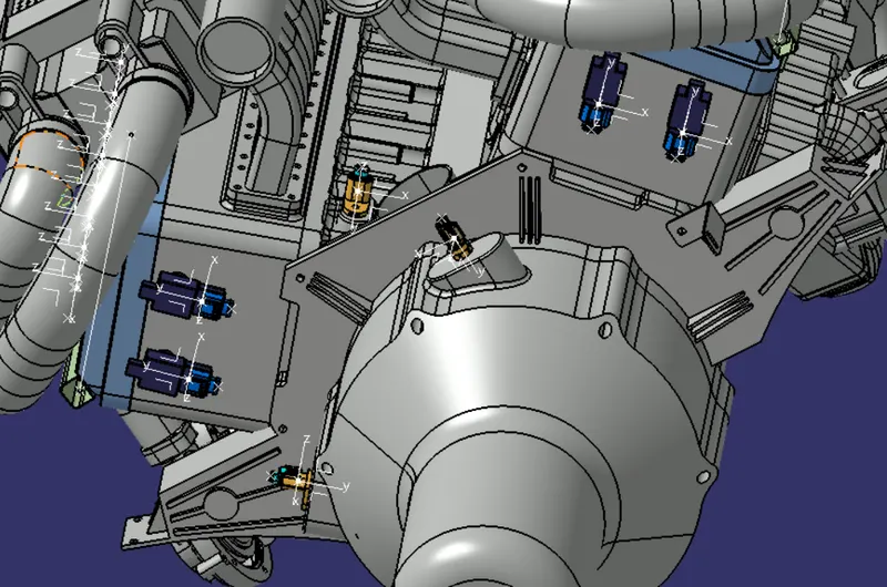
- 1 neutral position sensor connector and 1 speed sensor connector on the gear box housing.
- 1 engine coolant temperature sensor placed at the center of engine.
Now we need to plcae the conncetors according to the respective positions by using th emanipulations,smart move & compass.
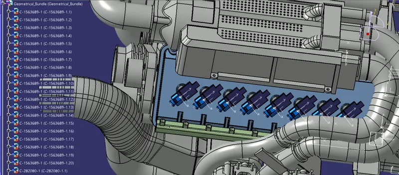
Step_08:Adding 4 pole connectors to all fuel injector sensors as well as for the camshaft sensors.
- 4 pole connector(c-1563689-1) should be added in the geometrical bundle by adding the exsiting component cammand in the assembly workbench.
- Place the connector in its position using the manipulation tools like move, smart move, snap tool and also using the compass.
- Now we need to copy and paste the conncetor one and place it in the preffered position using the same manipulation commands.
- Similarly we need to do it for other connectors and plcae them in theire positions.
-
Now we need to place all the other connectors for sensors like coolant heat sensor, neutral position sensor, speed sensors.
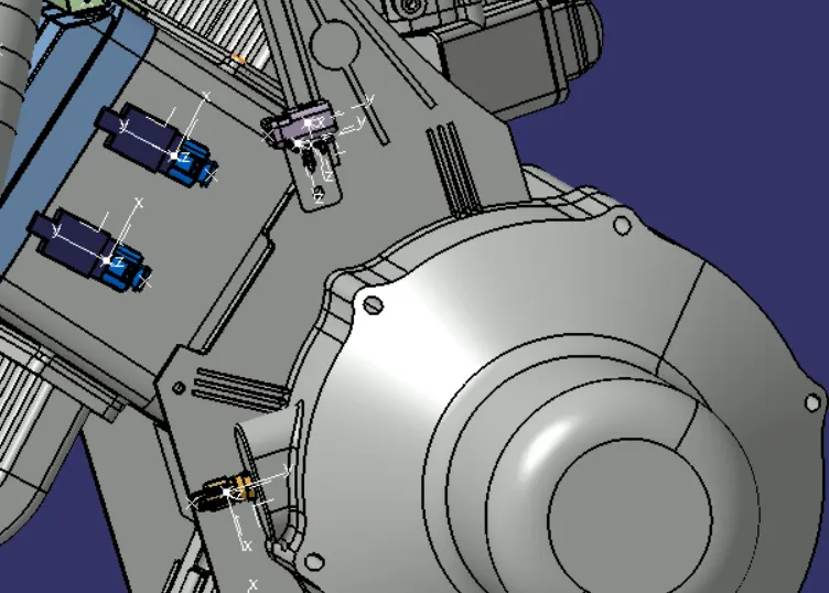
- Placing the Interconnection connector and L-clamp support over the Engine.
However, the situation of interconnection connectors is not similar to that of device connectors. Interconnection connectors are not parked with any device,but they should be parked with the help of clips/clamps/sheet metal brackets etc... possible to the packaging conditions.
Un-parked connectors can create the following issues-
- Rattling noise
- Physical damage to the connectors
- Uncontrolled Harness routing
- Manual errors during the assembly because of the undefined parking.
Assuming the bundle connection from the chassis is coming from the right side of the engine and therefore L-clamp is provided on the right side of the engine,which provides proper support for the interconnection connector. Here the cavity clip is inserted into the hole provided on the L-clamp.
- Adding P-clamps wherever necessary for the proper Routing of the harness bundle.
Adding supporting components like p-clamps and furr-tree clips can help the harness bundle provide proper routing and also help to prevent the harness bundles fouling from unwanted mechanical components.
- P - Clamp and the Furr Tree can be placed at required locations to ensure best possible routing for the harness bundles.
- The p – Clamps can be mounted to the holes provided on the Engine block in which the screws to tighten the Engine block.
- The Fir tree clips are positioned at the corners according to the requirement during the wire harness routing to avoid the fouling.
- After finalization of the routing, we can request the Engine design team to provide the holes for the Furr tree clips as per their location.
-
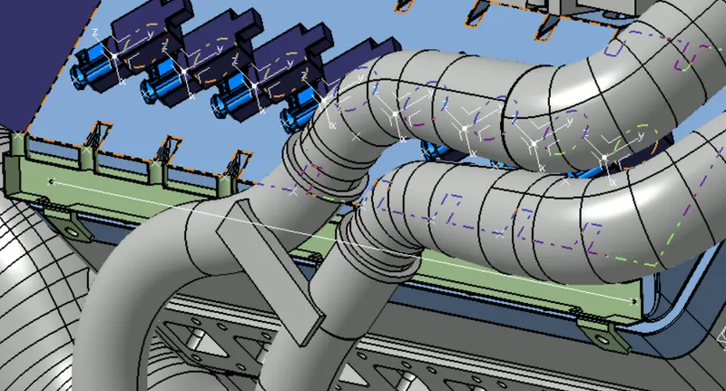
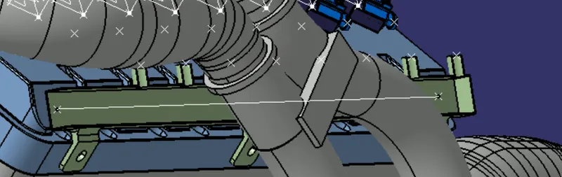
Placement of Guiding Channels at the required Locations
Use of plastic guiding channels are recommended to meet the clearances in critical areas, if it is difficult to achieve it by use of clamps.For placing the Guiding channel we need 3 holes to mount the channel over the engine for that , we can request the Engine design team to provide the holes as per their location
Some important packaging rules and best practices to be considered during the wiring harness routing and placing of the clips and clamps are as follows –
- Branch length should be minimum 50mm.
- Minimum distance between clip and nearest branching point should be 25mm.
- The minimum distance between two breakout points should be 50mm.
- Limit the number of branches from single branching point to 4.
- Wiring harness routing shall provide ease in manufacturing,accessibility,easy removal and easy maintainance of attached equipment and wiring harness.
- Routing through small structural holes and openings shall be avoided,to minimize chaffing and handling of the wiring harness during installation.
- Routing shall provide enough slack for each branch to avoid adiitional stress on wires and to avoid fouling.
- Avoid routing harness over the bolts,Near to the bolted joits or scrwed joints.it may damnage harness or May puncture the harness.
- Keep the harness away from the panel mounting screws or bolts.
- Avoid routing wiring harness near the exhaust manifold and its components and also from other unshielded heat sources. If the routing is not possible then maintain a minimum distance of 200mm.
- Enough clamps shall be provided to ensure positive clearance with surroundings and safety of wiring harness.
- Distance between two clmaps on a straight branch should be maximum 200mm.
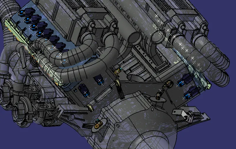
Keeping all the above packaging rules we can start the routing of the wire and provide clipping and clamping wherever necessary during the routing process.
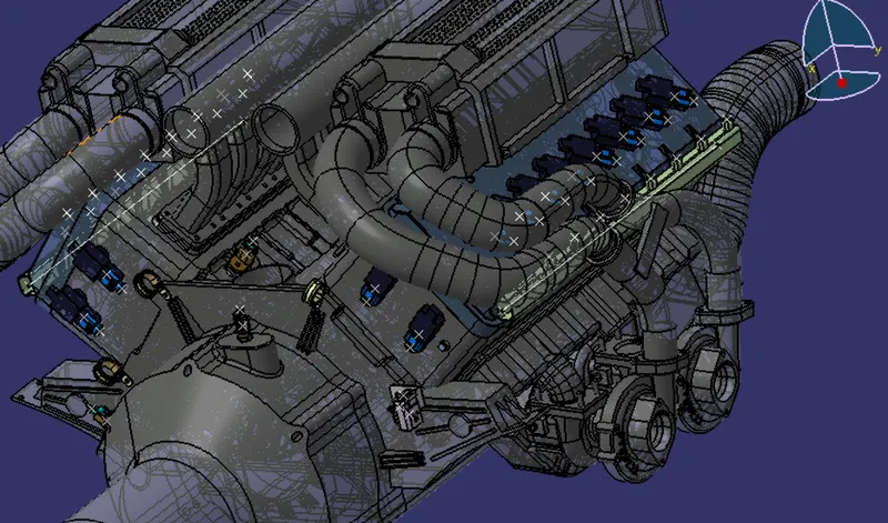
ENGINE with all the components for wiring harness routing.
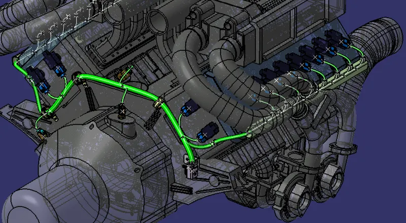
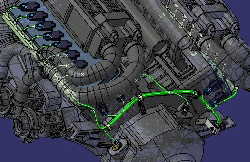
Step_09:Define the bundle as Geometrical bundle and then by using Mutli-branchable document create the brnches between the conncetors and add branching point if needed.
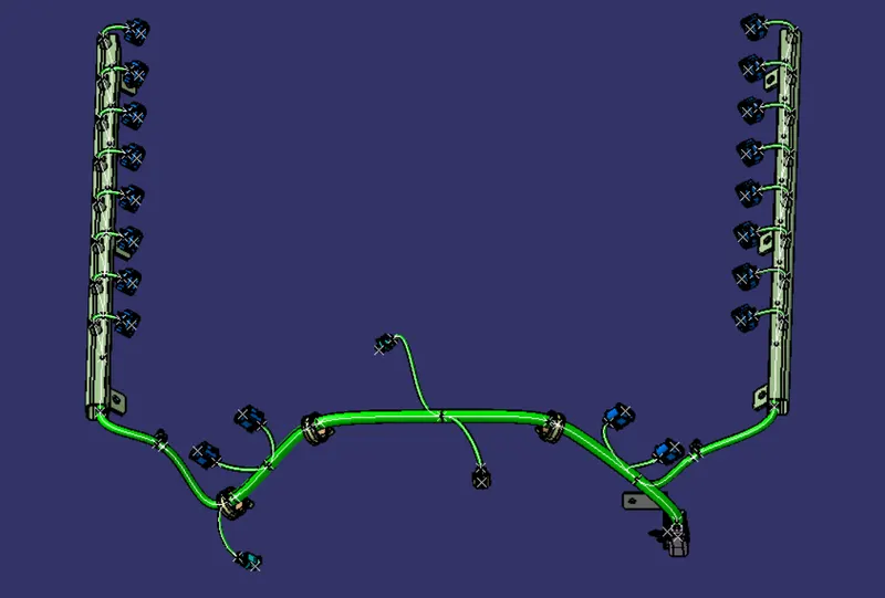
Step_10:
BUNDLE CONNECTIVITY CHECK:
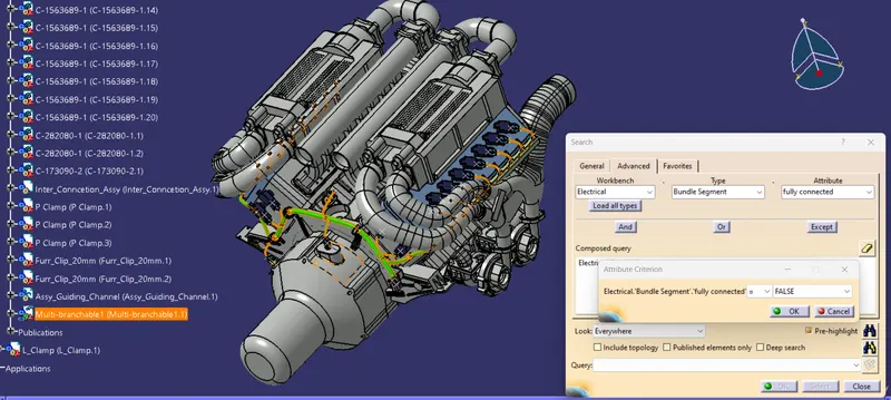
For proper flattening of the bundle in Bundle flattening assembly, we need to ensure that the bundle created is fully connceted.
- Activate the Mutli Branchable Document >> Goto Edit >> Search >>Advanced
- Set the Attribute creation to "Flase" since it is easy to check the bundles that are not fully connceted.
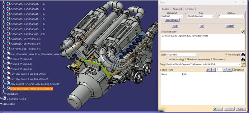
As we can see that there are no elements visible in the dialog box since all the branches are fully connceted.
Engine Assembly:
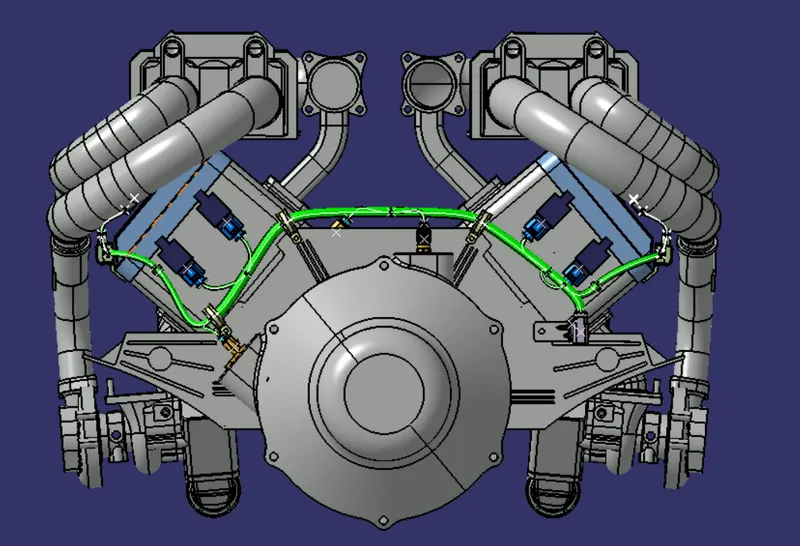
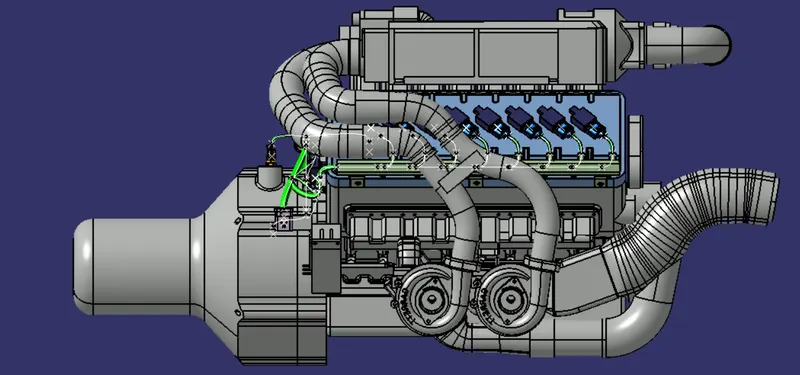
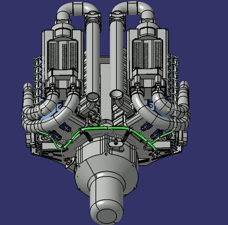
Step_11:WIRING HARNESS FLATTENING
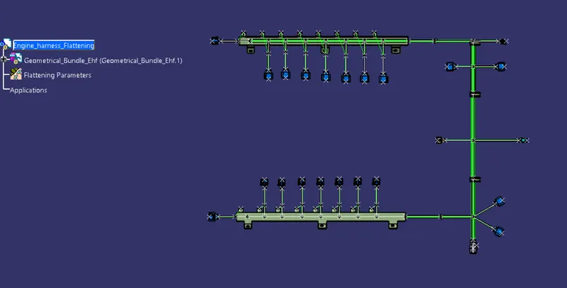
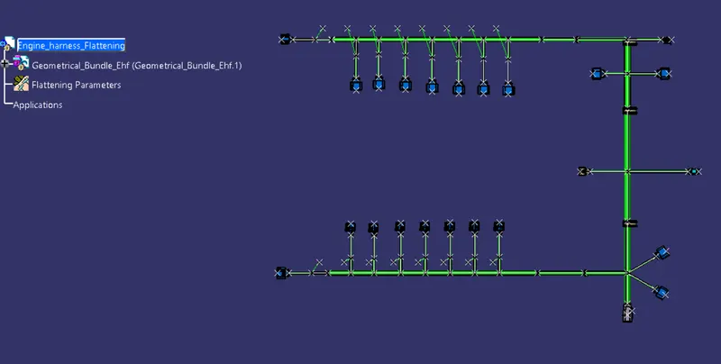
Now we need to convert the geometrical bundle into a flattened wiring harness in the "Electrical Harness Flattening" Workbench.
- To create the Flattened Harness, we need to create a new product file and switch into the Electrical Harness Flattening workbench.
- By using Harness flattening parameters edit the parameters as shown in the below fig.
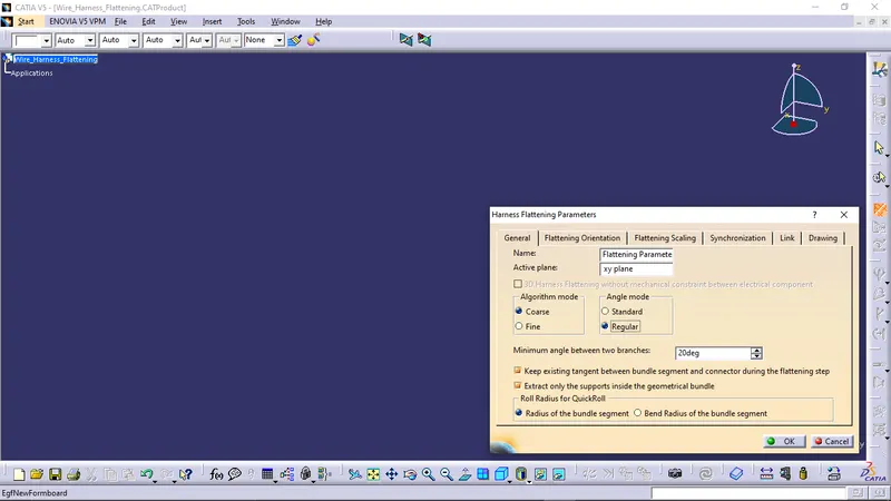
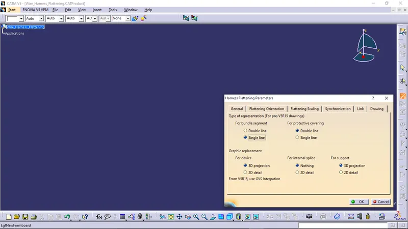
-
Select the 'Extract' option from the "Electrical Harness flattening workbench" and select the Geometrical bundle product in the wire harness assembly product file.Then wire harness assembly is imported to the Wire flattening product file with '_EHF' extension added to the geometric bundle assembly name & by using flatten command make the bundle flat.
Step_12: FLATTENED HARNESS VIEW IN THE DRAWING SHEET
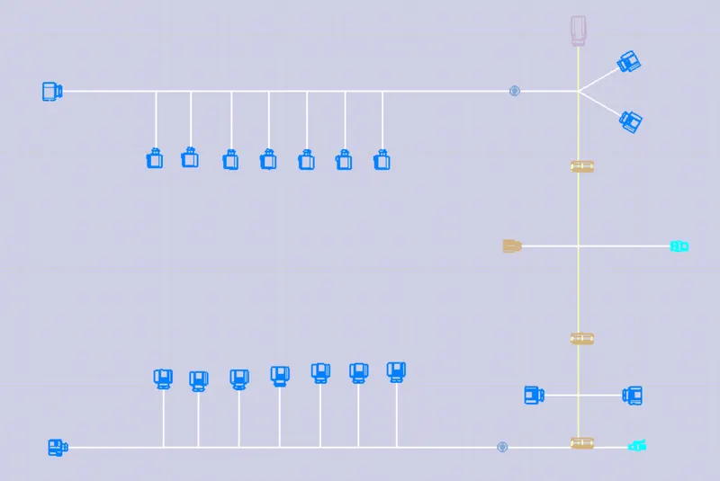
Now we need to create a drawing file for the flatten part,for that create a new drawing file and by using the front view option select the view of the bundle and adjust it according to the sheet and make neccessary settings for that.
CONLUSION:Routing the Wiring harness on Given 16V Engine is done and Preparing the flatten view drawing in CATIA V5 is also made succesfuly.