A pillar Design with Master Section
The given CLASS A SURFACE is to be checked properly,for making sure the given surface has no gaps.Once if it confromed ,then go for tooling axis creation , by using boundary.If any gaps we need to work on it and not we can continue with creating the,tooling axis,intial draft analysis and then b surface.And then extract the surface for creating the tooing axis.
Tooling axis creation:check the given surface completely to identify the location of tooling axis,always select the surface which is flat and when viewing from the normal view ensure all the surface can be completed with that view.
The tooling axis is created such that tha draft analysis can be done by that tooling direction.we have 3 conditions for this
1.with respect to the axis system(x,y,z axis)
2.normal to surface
3.bisecting mecthod
If any one condition is satisifed then continue with that condition.
In this challenge let us consider the mastersection and create the tooling axis w.r.t to the back curve using point to point method as the master section is going to clear the draft anlysis by suing that tooling axis.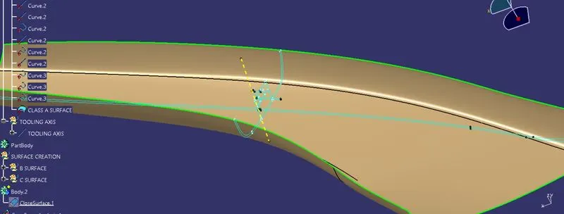
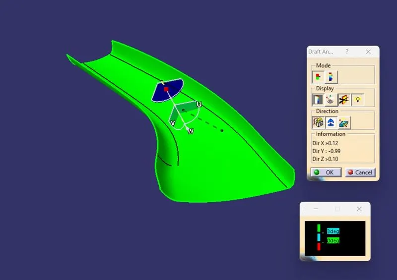
DRAFT ANALYSIS: Once the tooling axis is completed then we can proceed with the draft analysis of the given surface.For that open Feature draft analysis and select modes to set proper mode options which shows 3 colors(blue, red,green).The green is preferable and set the draft angle to 3 deg.Then goto display option and click on analsyis under running point and check the angles on all thesides os the surface,and goto direction option selection compass and drag it into the tooling axis and fit in it such that the w face should coincide with the tooling axis.If the surface is in blue color change it to green by using flip option in the directions.Initial darft analysis of the class A suraface is shown below. in this case we take draft angle as 3 deg with the main tooling axis.
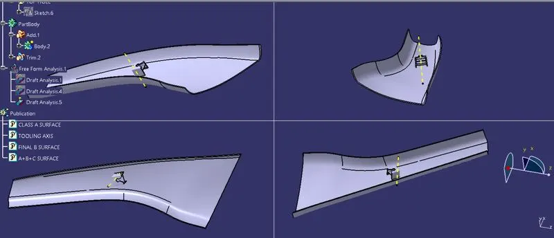
final draft anlysis of the part body without B side features is considered as 2.85 deg.
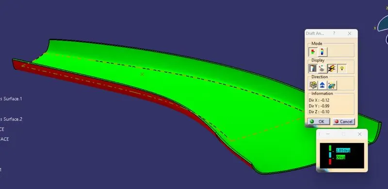
Draft anlysis along with the B side features w.r.t to the main tooling axis.
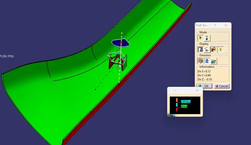
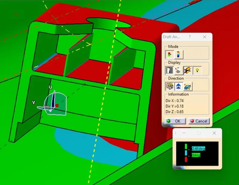
THe draft anlsis of the dog house inner portion w.r.t the side core tooling axis is takenn as .45 deg.
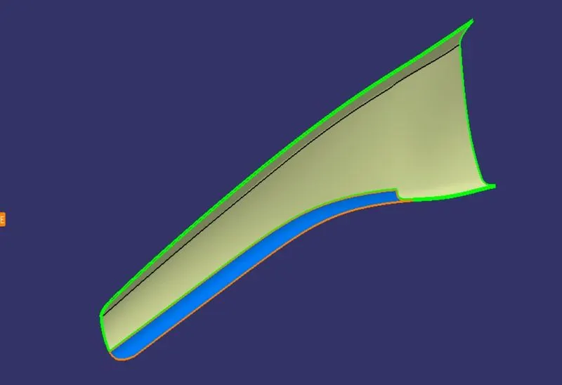
CLASS B SURFACE CREATION:For creating the B surface,the given A surface is offseted to 2.5mm as given.we can observe a patch over the surface.which we are going to work on it.This pacth can be cleared by using commands like boundary and sweep.The surface is to be extrapolated all around by a minimum thickness so that when trimmed with A+C surface there will be no issues.THe yellow color surface is the offset and the blue color is the given CLass A surface.
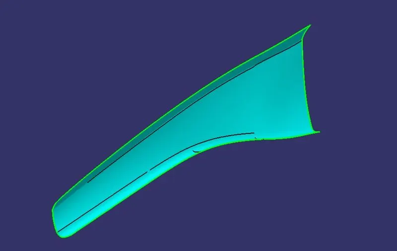
THe above fig shows the final B surface after extrpolating.
CLASS C SURFACE CREATION:Once the B surface is created we need to work on C surface.The c surface can be created part by part from the given class A surface.For creating the Class C surface we are going to use two options
1.with reference surface-if the c surface is perpendicular to tooling axis (90 deg)
2.with draft direction-if the c surface is parallel to the tooling axis.
The sweep craeted w.r.t the draft direction should be 3deg outside .
At fillet areas we are going to use multi section surface so that ther be will be no issues.all the sweep part sare joined at the end as one surface.ensure proper length while creating the c surface so that it must overlap with the b surface.
Once it is done we have to join the sweeps & class C surface with A surface and then trim with B surface and close the body by using close surface.
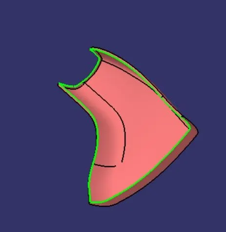
The final A+B+C surface is shown below.
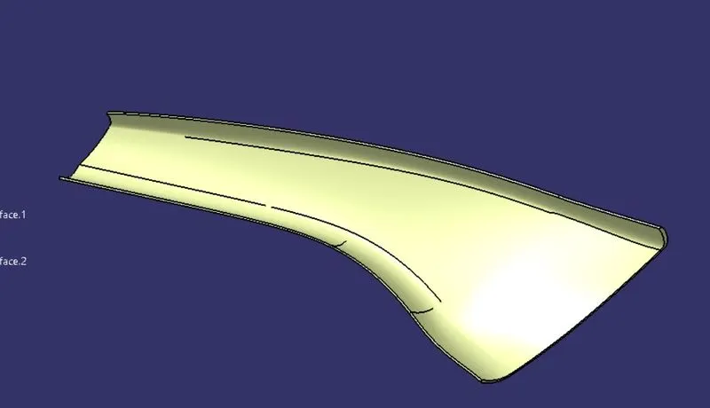
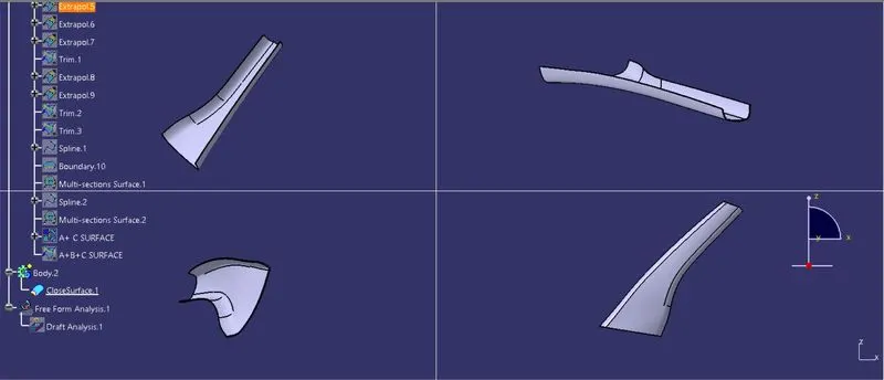
Now goto part workbench insert a body,define work object and then close the surface by using close surface command.the below isometric views of the part body are shown below.
Creation of B side features using master sections: From the Given master section we can understood that it is a dog house.SO we need to create a DOg house using the mastersection.We need to make a sketch taking the mastersection as ref.
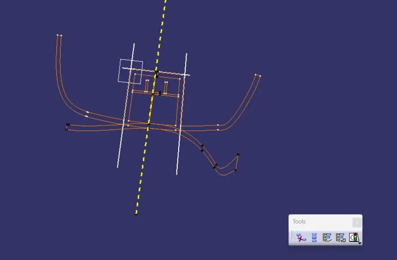
Extrude the line and then trim them.
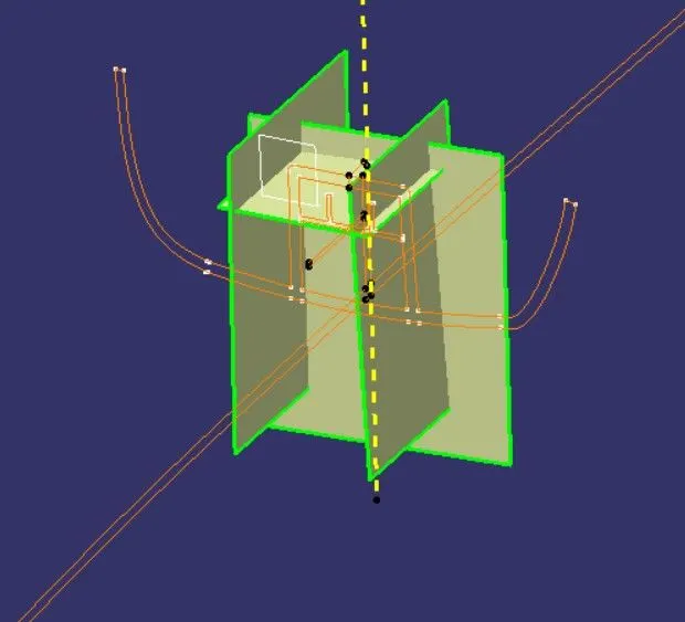
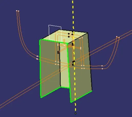
now Using thicknen command given a thickness og 2.5 mm in the inside didectio so that a partial dog house have been created
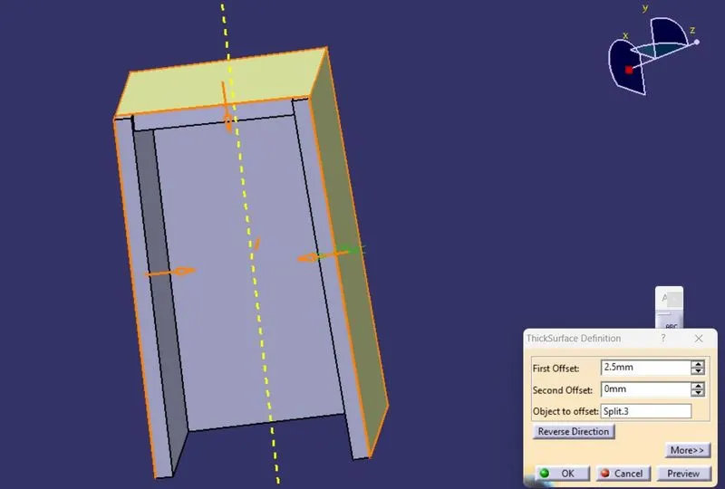
now using mutiple extract select the inner walls and then offeset them with 40%of the thickness that is approximately 1mm and extract using poin continutity and then trim the surface with the offset of the bottom surface.
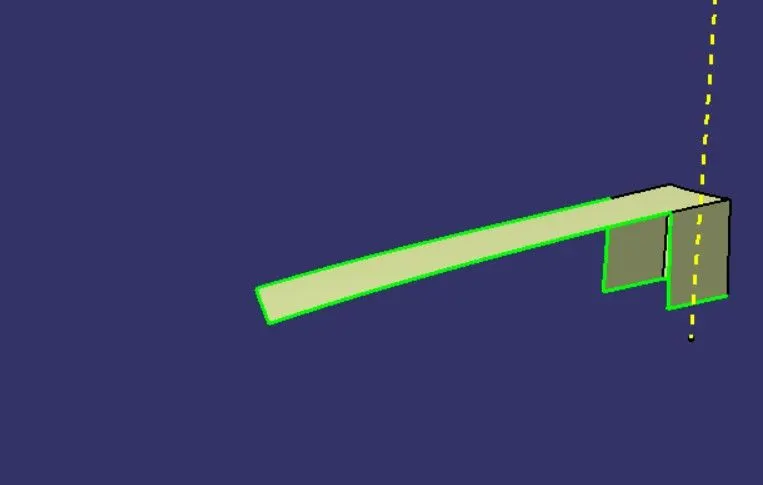
NOw spilt te obtianed surface with the closed body thn we will get the required C area in the dog house.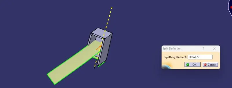
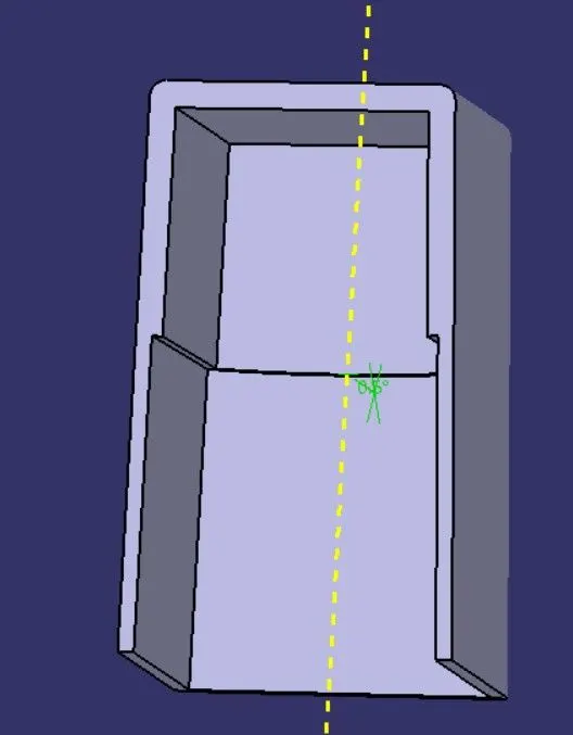
We have to give fillets to the outer areas and draft to the inner area w.r.t the side core tooling axis of .5 deg.
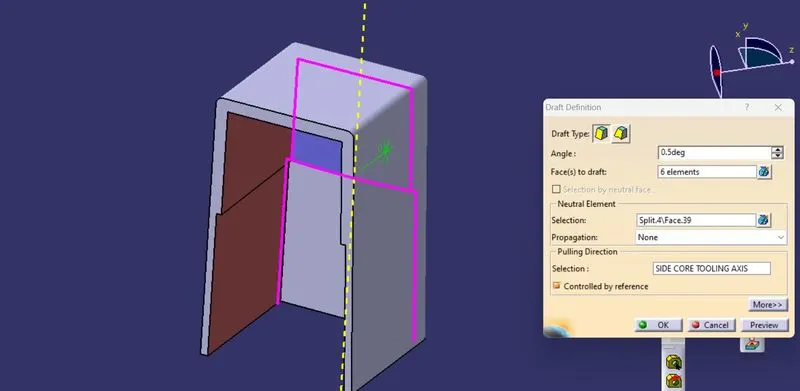
Now we have to create the ribs along with the top hole.we have to take the ref from the mastersection and create line and then extrapolate it and thn given thivkness to it.
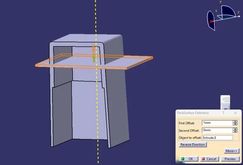
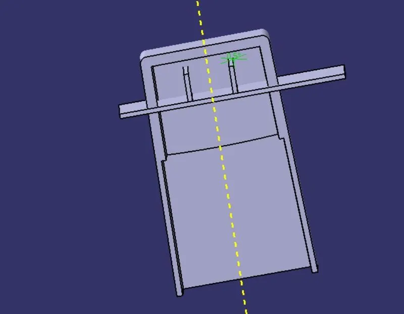
we have to give draft to the ribs of 0.5 deg
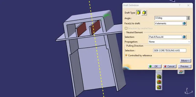
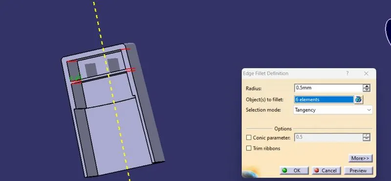
Using boolenn operation remove the excess part by using union trim with the dog house.and then fillets to be given at the area with minimum of 0.5.
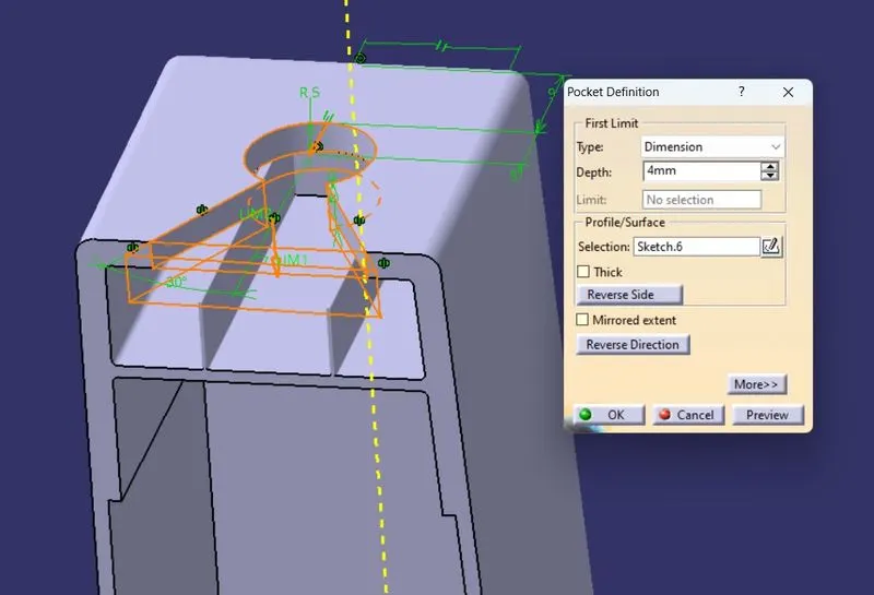
Now the hole is creatd at the top of the dog house adn then by using pocket command we can get the hole on the top of the dog house.
Once the dog house is completed define the main part body and union trim the face which we dont need of the dog house.
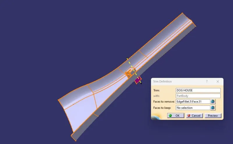
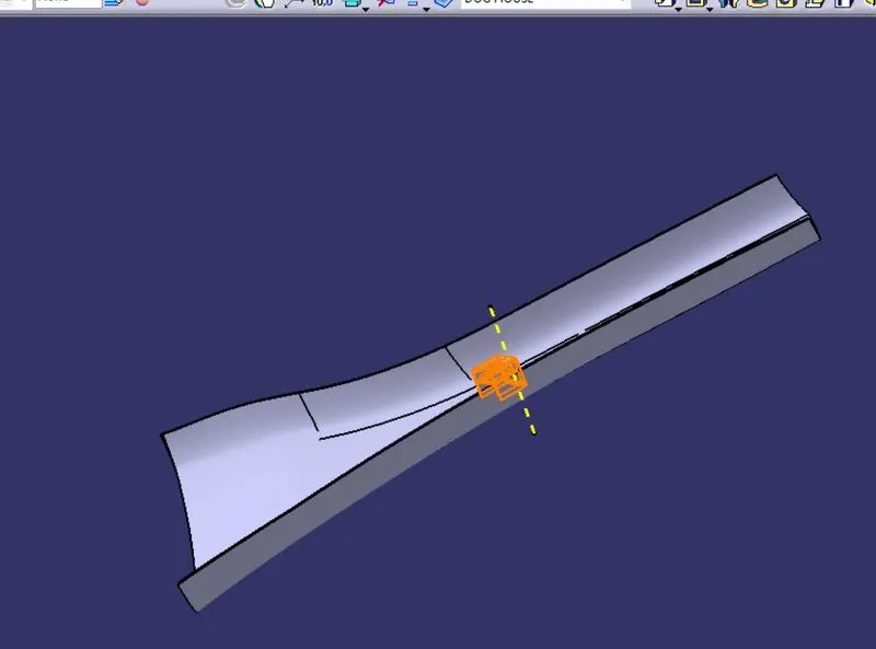
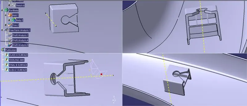
DOg house draft anlysis.
Part body draft anlysis.