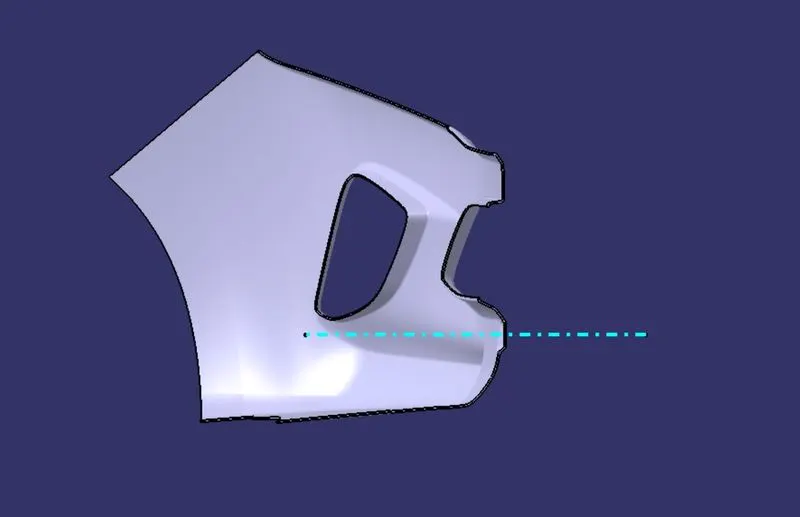
Bumper Design
The given CLASS A SURFACE is to be checked properly,for making sure the given surface has no gaps.Once if it confromed ,then go for tooling axis creation.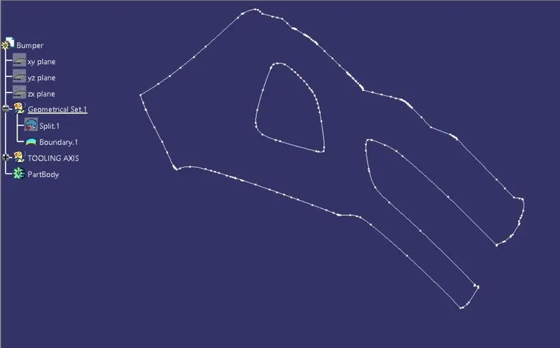
TOOLING AXIS: check the given surface completely to identify the location of tooling axis,always select the surface which is flat and when viewing from the normal view ensure all the surface can be completed with that view.
The tooling axis is created such that tha draft analysis can be done by that tooling direction.we have 3 conditions for this
1.with respect to the axis system(x,y,z axis)
2.normal to surface
3.bisecting mecthod
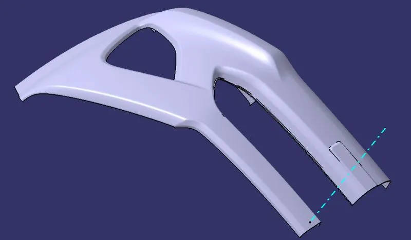
In bumper challenge,let us consider the axis system,take the given surface and extract the flat surface and then make a line by using point direction method,lets check the draft analysis with the tooling direction.In this case the draft analysis is going to clear ,so we can named the line as tooling axis.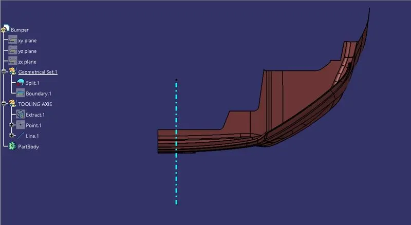
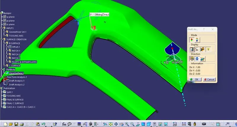
DRAFT ANALYSIS: Once the tooling axis is completed then we can proceed with the draft analysis of the given surface.For that open Feature draft analysis and select modes to set proper mode options which shows 3 colors(blue, red,green).The green is preferable and set the draft angle to 3 deg.Then goto display option and click on analsyis under running point and check the angles on all thesides os the surface,and goto direction option selection compass and drag it into the tooling axis and fit in it such that the w face should coincide with the tooling axis.If the surface is in blue color change it to green by using flip option in the directions.Initial darft analysis of the class A suraface is shown below.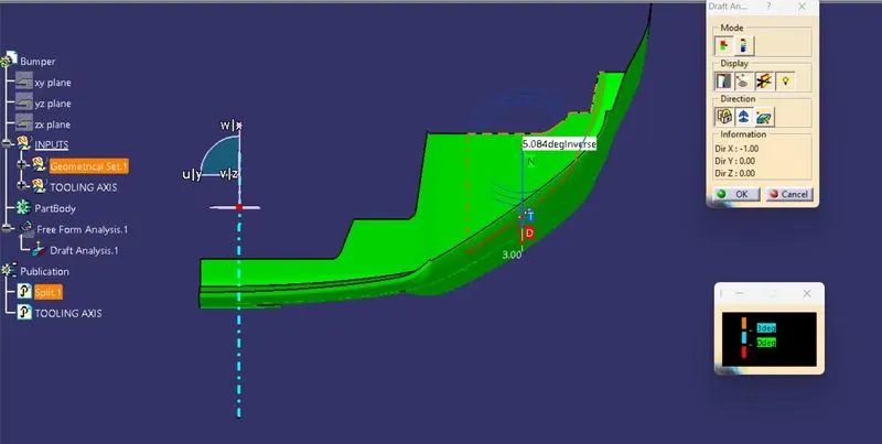
The final draft analysis os the CLASS A + CLASS B +CLASS C is shown below.In this case we have set the draft angle to
2.9 deg so that the side boundary will also changes to green color.
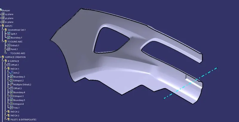
CLASS B SURFACE CREATION: For creating the B surface,the given A surface is offseted to 3mm as given.we can observe three small pathces around the surface.which we are going to work on it.These pathes can be cleared by using command s like join,boundary,extrapole,trim ,multi section.Once The patches are covered we are going to give fillet radius so that the B surface can be completed.This is the final B surface.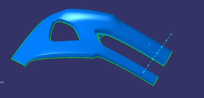
CLASS C SURFACE CREATION:Once the B surface is created we need to work on C surface.The c surface can be created part by part.For creating the Class C surface we are going to use two options
1.with reference surface-if the c surface is perpendicular to tooling axis (90 deg)
2.with draft direction-if the c surface is parallel to the tooling axis.
ensure proper length while craeting the c surface so that it must overlap with the b surface.
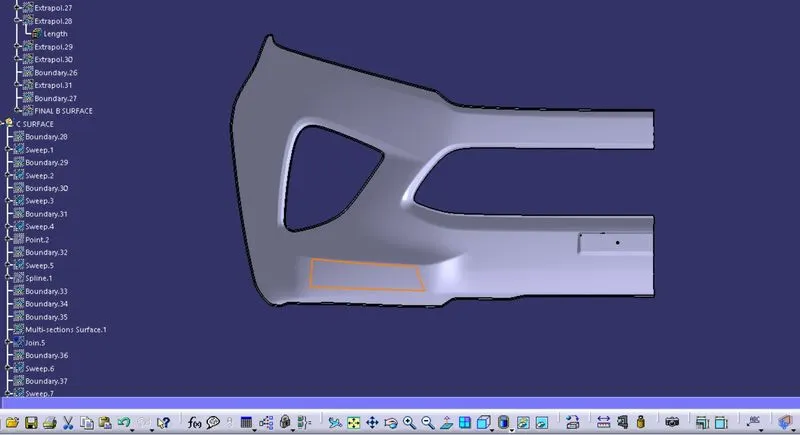
The final c sruface is shown below.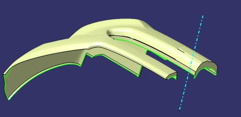
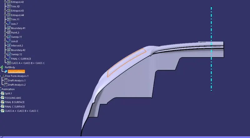
Now The given A surface and C surface can be joined by using join command.then the final obtained surface is trimmed with the b surface.Ensure that the B surface and c surface intersects each other ,if not extrapolate the surface to required length.The final classs A+B+C surafce is shown below.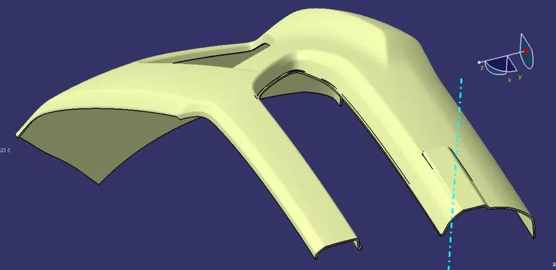
Go to part workbench the close the surface bu using close surface command.The isometriec views of the final part body are
shown below.