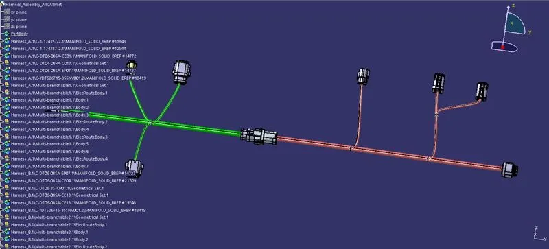
Wiring harness design in CATIA V5
AIM: To route the following harness layout in Electrical workbench and making assumption for harness bundle diameters and to use the connectors provided.
OBJECTIVE:
After completion of routing,
- Check the bundle Continuity. Add snap of result in submission
- Add annotation to all connectors. Make an assumptions for annotations like connect 1 , 2 etc
- Check for the bundle warning. Add snap.
- Generate CAT.part of harness assembly and convert is in. igs format.
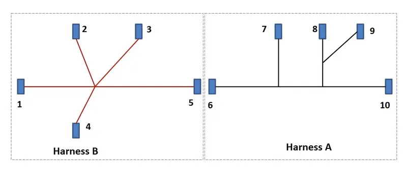
Given layout shows two Harness A and Harness B & the electrical connectors are represented by numbers in the below figure. There are 8 different types of connectors at 10 different locations.
STEPS TO BE FOLLOWED:
- First download all the components from the link.
- Provide the required geometrical parameters like points,axis system.
- The points are to be created by using point>>between command at the bundle entry point and the connector connection point.
- Create an axis system at the connector connection point.
- Then Switch to "Electric Part Design" and define the part as connector in catia v5, give no. of terminations as per the conncetors usage.
- Define Bundle connection point.
- Define connector connection point.
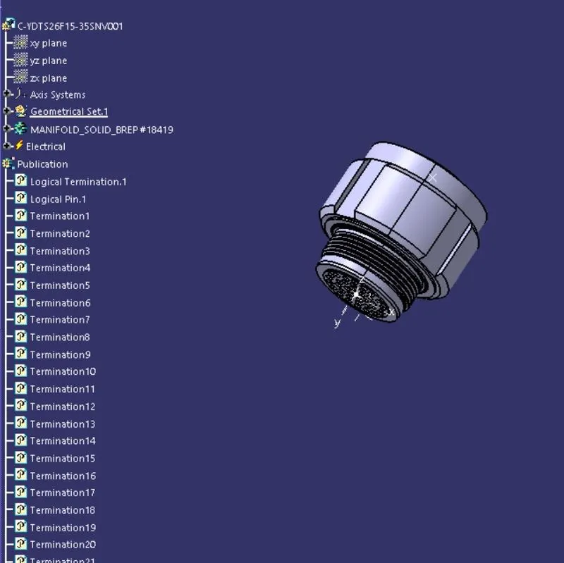
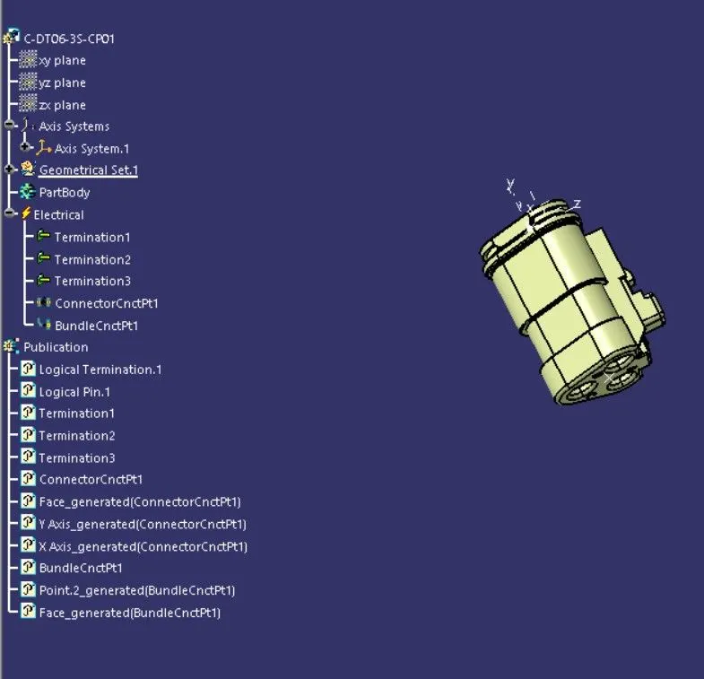
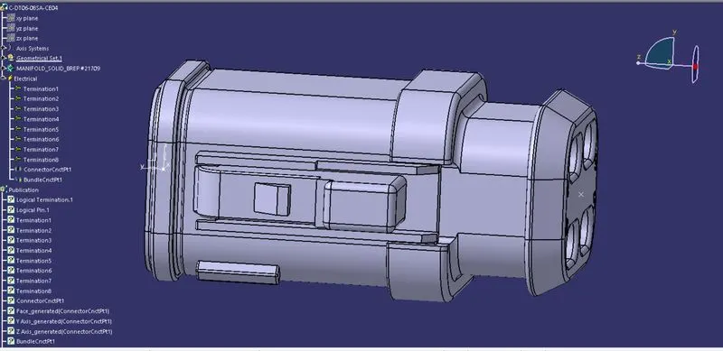
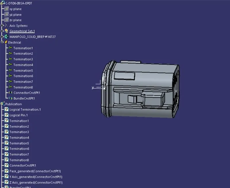
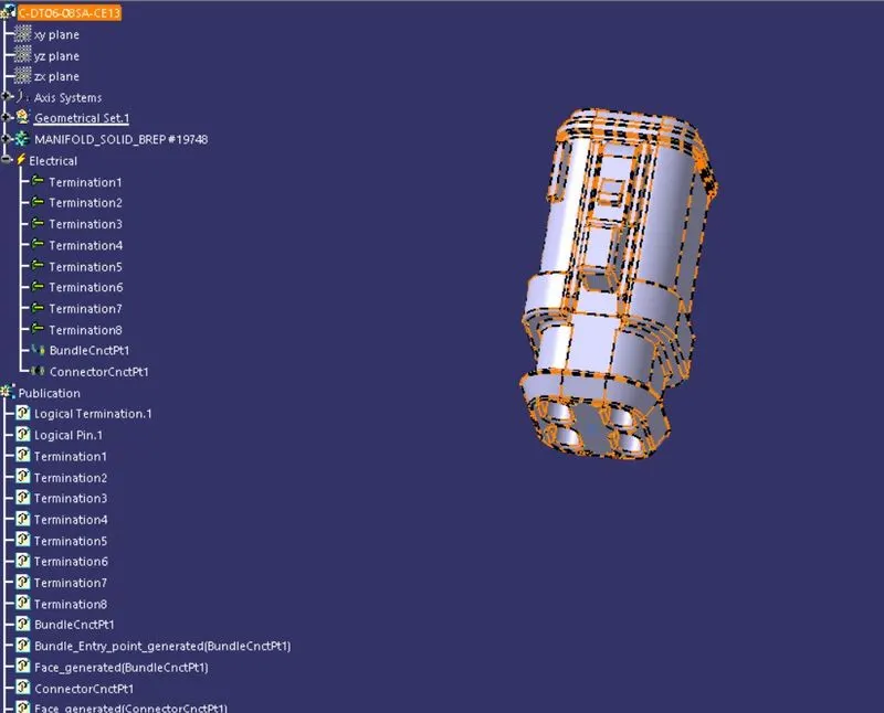
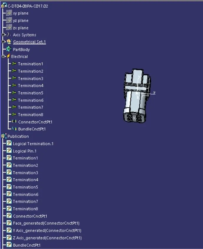
- The below figures shows the conncetors that are electrically defined.
conncetor 1 (C-YDTS-26F15-35SN001)
conncetor 2 (C-DT06-35-CP01)
conncetor 3 (C-DT06-8SA-CE04)
conncetor 4 (C-DT06-08SA-EP07)
conncetor 5 (C-DT06-08SA-CE13)
conncetor 6 (C-DT04-08PA-C017)
conncetor 7 (C-1-174357-2-e)
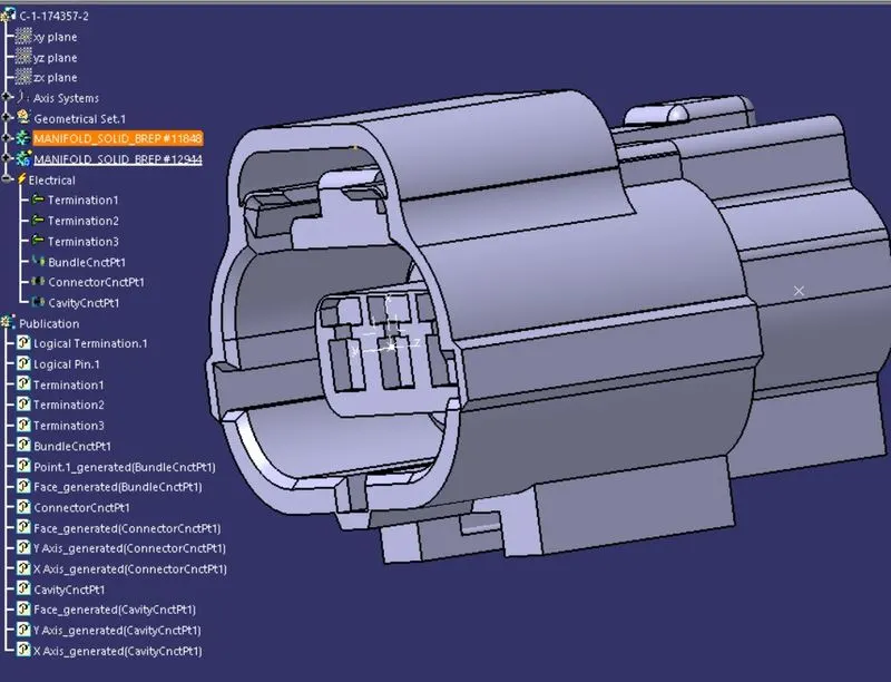
conncetor 8 (C-DT06-8SA-CE01)
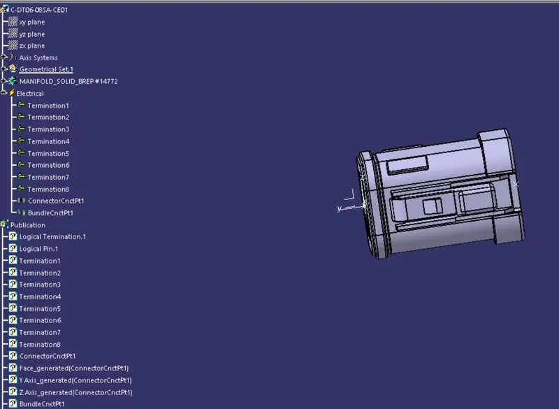
conncetor 9 (C-DT06-08SA-EP07)
conncetor 10 (C-YDTS-26F15-35SN001)
- The conncetors from 1- 5 are for Harness-A & the conncetors frm 6-10 are for Harness-B.
- Now copy the connceors that belongs to Harness-A & create a new product file and paste them in it naming the product file as Harness-A.
- Goto "Electrical harness assembly" and place the conncetors according to the given layout by using the help of the compass.
- Define the bundle as Geometrical bundle and then by using Mutli-branchable document create the brnches between the conncetors and add branching pint if needed.
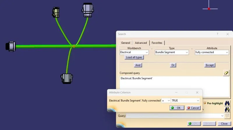
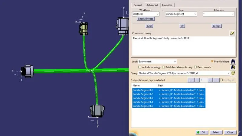
- Once it is donce check the bundle connectivity for that doble click the Multi branchable document to active ,then goto Edit>>search and then follow the figure.
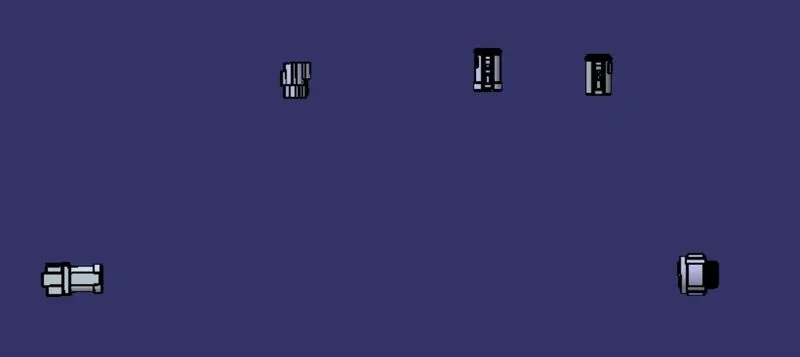
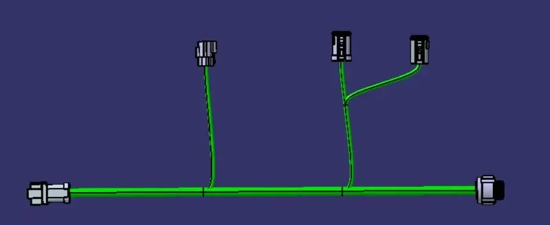
- Once it is donce check the bundle connectivity for that doble click the Multi branchable document to active ,then goto Edit>>search and then follow the figure.
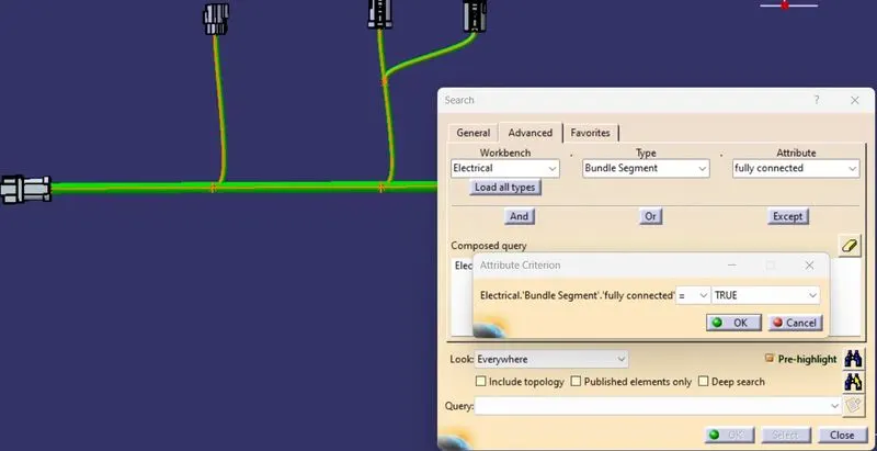
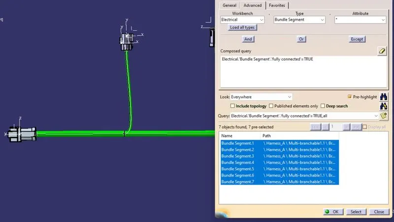
- The figure shows that all the bundles are fully connected.
- Similarly do for Harness-B.
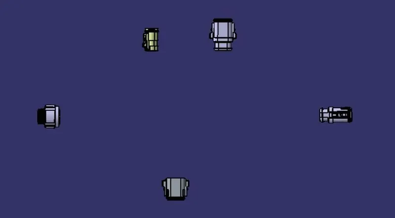
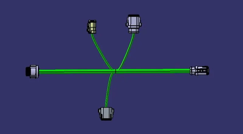
PROBLEM STATEMENT:
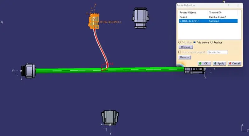
If the bend radius is not sufficeint bwteen the two conncetors then there will be an error in creating the bundle,so to avoid that error there are 2 options
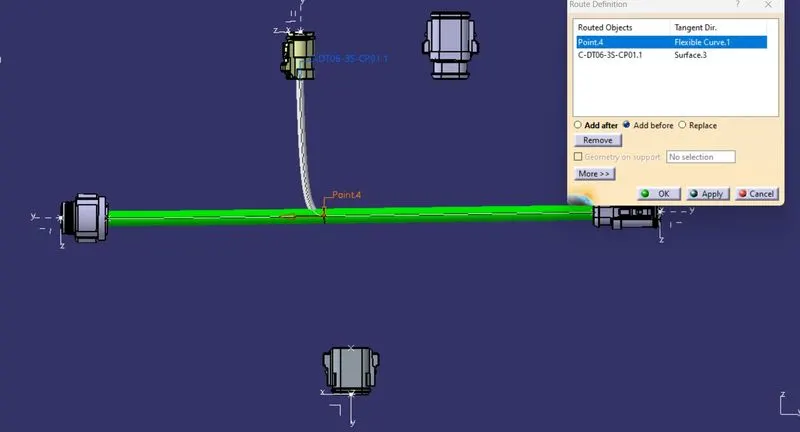
- Goto route definition try to reverse the tangent direction for the conncetor always ensure that the direction shold be inbetween the two conncetors.
- Increase the slack % so that it can be resolved or try or move the branch point .
In our case the error had resolved by reversing the tangent direction for the point which is shown below.
Now create a new product and switch to "Electrical assembly design" and paste the 2 harness assemblies in it.By using connect electrical devices ,conncet the Harness-a & Harness-B.
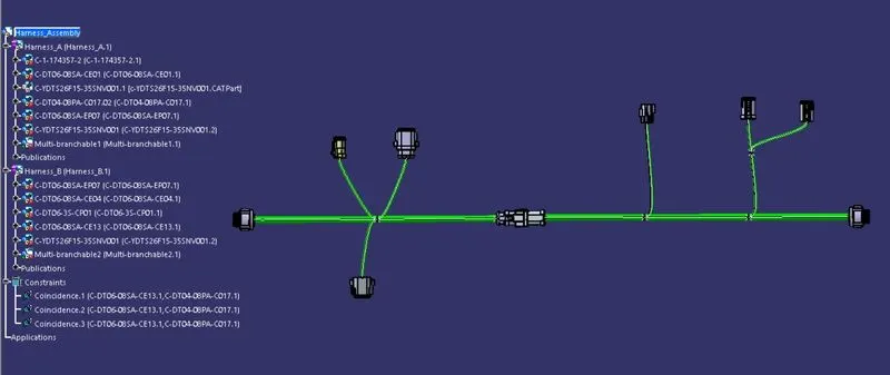
Now we can annote the conncetors for that switch to "Mechaniacl Assembly Design" and by using view creation select the plane for annoting the parts and then by using "Flag not with leader"annote the parts according to the layout.
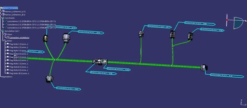
After annoting the conncetors we need to convert the assembly product into part file for that
Goto Mechanical Assssembly Workbench>>Tools>>Generate CATPART from Poduct.Now our product file is converted into part file and be converted into igs or stp file .