Wiring harness design in CATIA V5
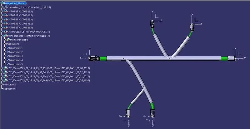
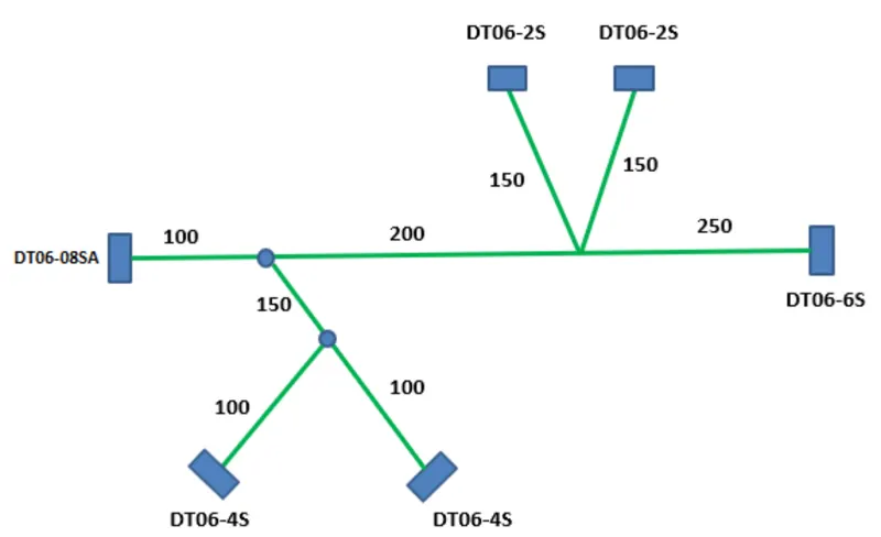
AIM:To Route the following harness layout in Electrical workbench and to make assumption for harness bundle diameters and add protective covering on all branches connected to DT06-2S & DT06-4S connectors. Keep end extremity at 30mm (from connectors end).
The following connectors are to used for making the electrical harness layout
- DT06-4S
- DT06-6S
- DT06-2S
- DT06-08SA
Connectors Layout Design:
For converting the mechanical component into electrical component these are the stes to be followed:
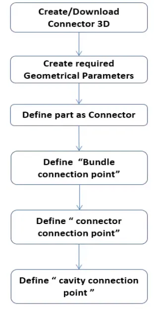
- First download the components(DT06-4S,DT06-6S,DT06-2S,DT06-08SA) from the link.
- Provide the required geometrical parameters like points,axis system.
- The points are to be created by using point>>between command at the bundle entry point and the connector connection point.
- Create an axis system at the connector connection point.
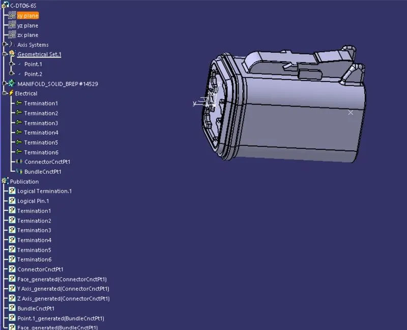
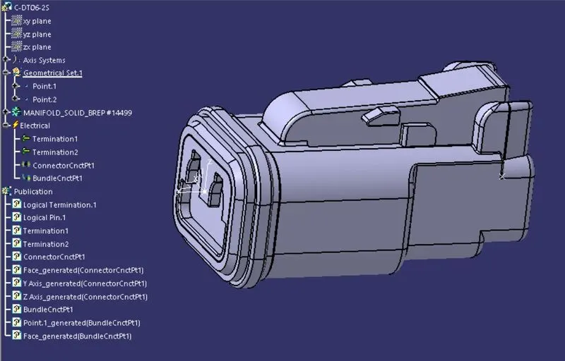
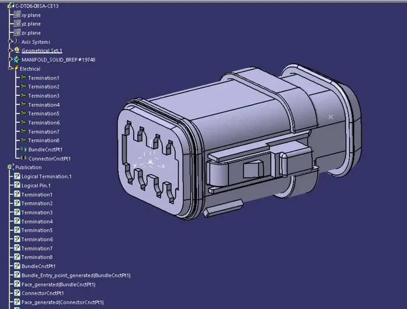
- Now Switch to Electric Part Design and define the part as connector in catia v5, give no. of termination according to the conncetor type.
- Define Bundle connection point.
- Define connector connection point.
1.DT06-4S:
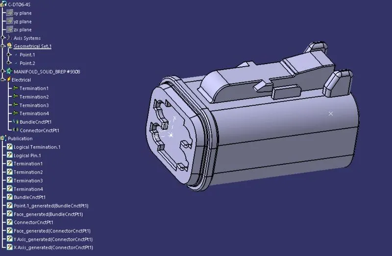
2.DT06-6S:
3.DT06-2S:
4.DT06-08SA:
Once It is done,goto part wokbench and prepare a sketch as per the layout by using the dimensions.

Goto >> electrical assemblyworkbench and copy past the entire sketch and the connectors and place them in appropriate position as shown in the fig.
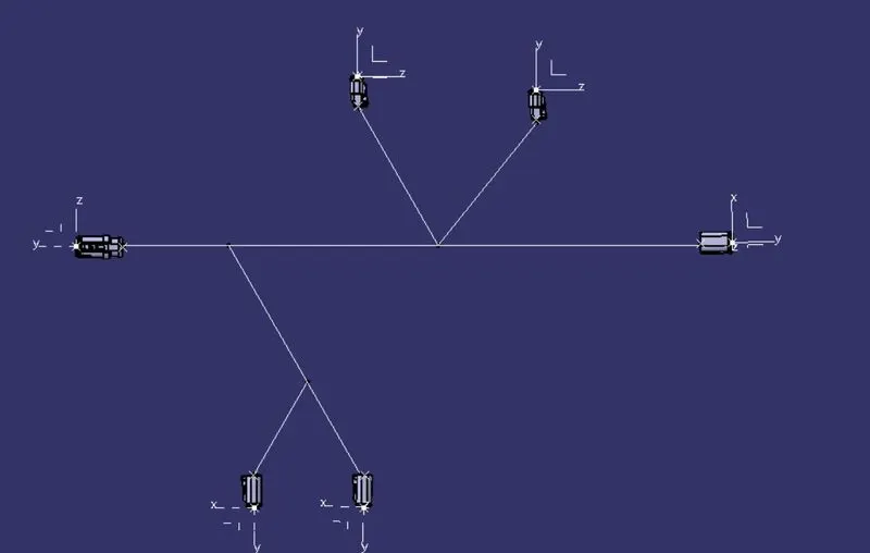
Now got "Electrical harness assembly " and then define the bundle eletcrially by using "Gemotrical bundle" option and then by using Multi branchable document make branches between the connectors.
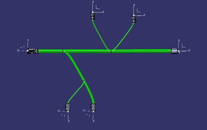
Once it is done add protective coverings over the branches and make the ends 30mm gap blw the conncetors and the branches.