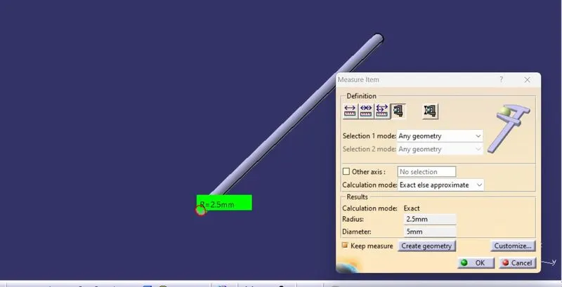
Wiring harness routing & packaging Rules
AIM:To define the given components as Electrical Connectors using Electrical Part design Workbench & to define all the necessary properties to the Connectors & Clip.
INTRODUCTION:
WIRING HARNESS:A wiring harness is an organised set of wires,terminals & connectors that runs throughout the entire vehicle & transmit the information and electrical power thereby playing a cruical role in connecting a vareity of components.The wirng harness is a combination of both mechanical & electrical data.
1. Download following cad data & define it as Electrical support using Electrical Part design Workbench. Define all the necessary properties.
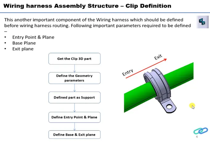
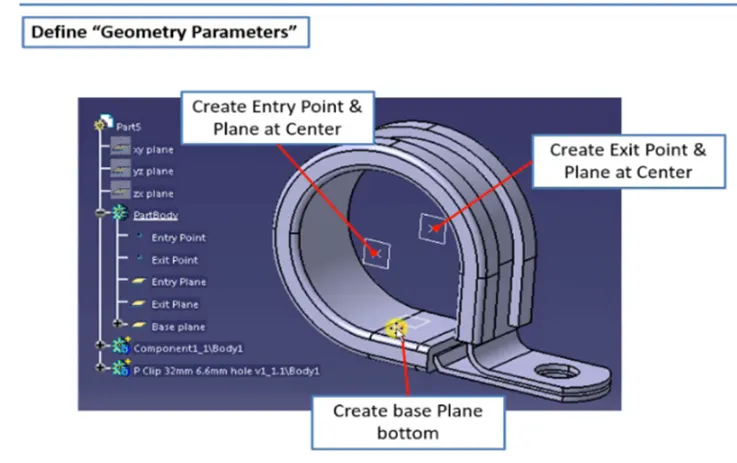
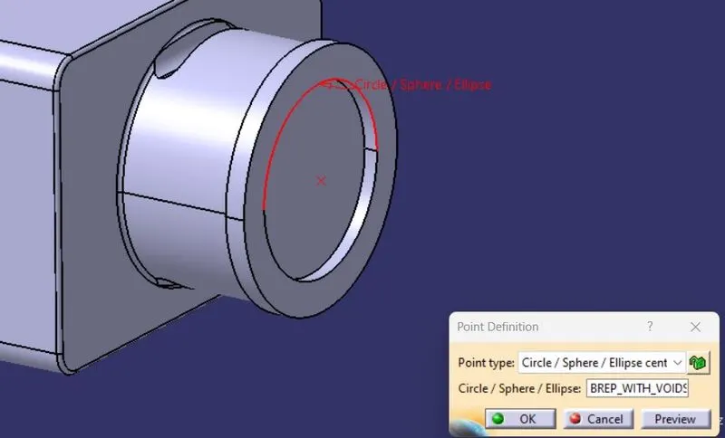
- Once downloading the partfile,create 2 pints for entry & exit by point>>center/sphere method.
- Create planes at that 2 points by using parallel through points and the base plane by using offset method.
- Now switch to Electrical part design.
- We need to define the part as support part for that,
- Click on "Define support part ">> select part >> select entry point, select entry plane,exit plane, and base plane.
- Again Click on "Define support part ">>select part >>select exit point ,select exit plane and base plane as the second plane is automatically taken.
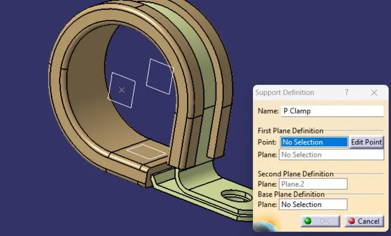
- Once the Entry side is sone the entry side point gets hidden and again do the same process for exit.
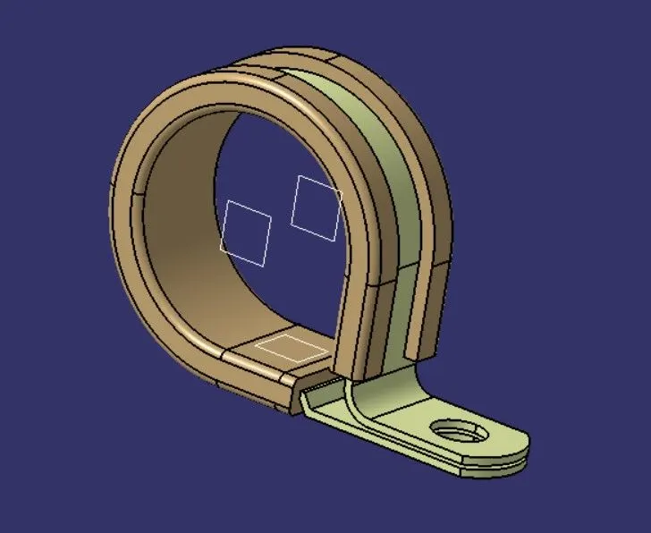
2.Download following Back shell cad data & define it as Electrical back shell using Electrical Part design Workbench. Define all the necessary properties.
Tyco 1738312-1 https://www.te.com/usa-en/product-1738312-1.html
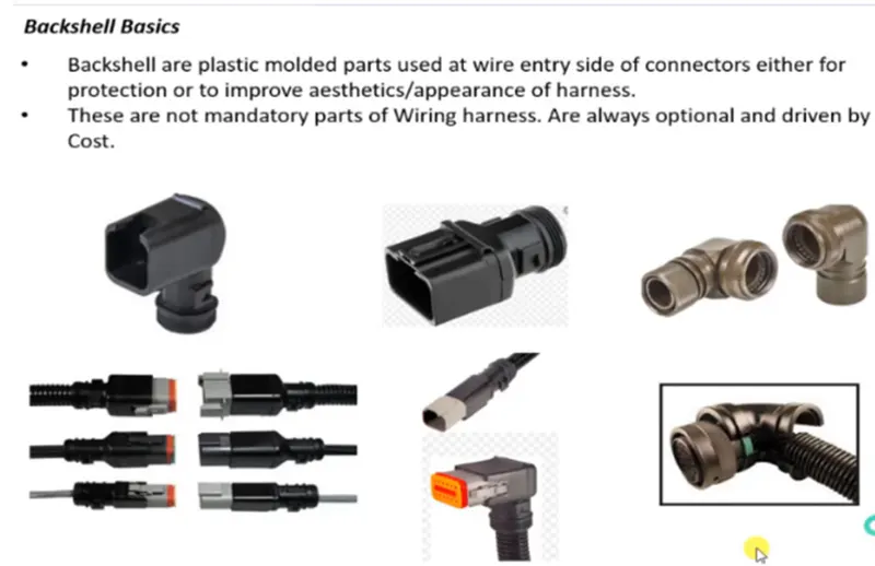
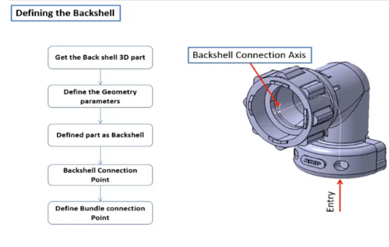
- First download the component from the link.
- Provide the required geometrical parameters like points,axis system.
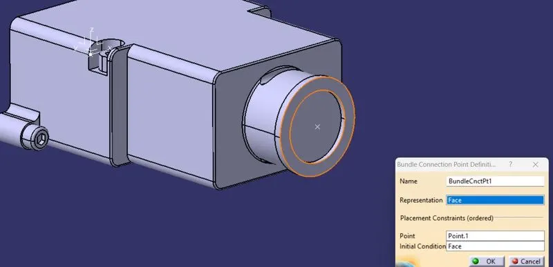
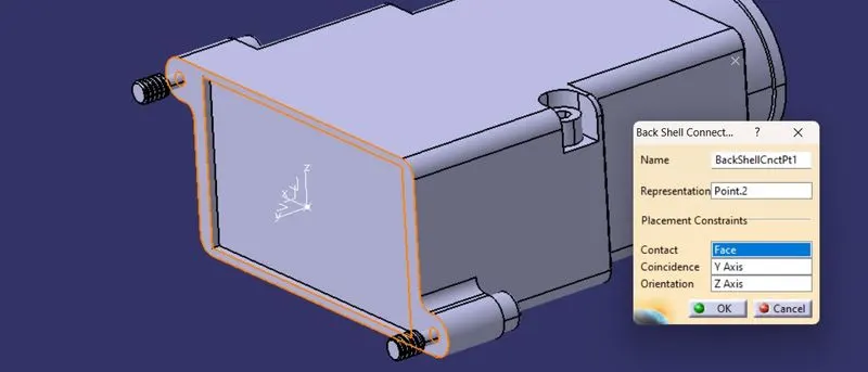
- The points are to be created by using point>>between command at the bundle entry point and the backshell connection point and an axis system at that point.
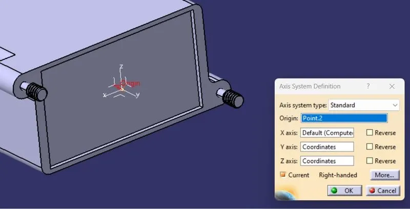
- Now Switch to Electric Part Design and define the part as Backshell.
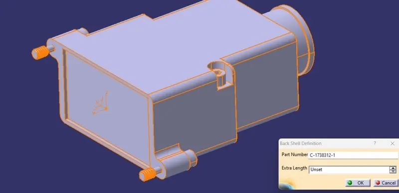
- Define Bundle connection point.
- Define backshell connection point.
3.Create Following Corrugated tubes & Add them in Catalogue under “Slit COT” family.
|
Name |
ID (mm) |
OD (mm) |
Thickness (mm) |
|
15mm COT |
12 |
15 |
1.5 |
|
20mm COT |
17 |
20 |
1.5 |
|
35mm COT |
32 |
35 |
1.5 |
|
10mm COT |
7 |
10 |
1.5 |
|
5mm COT |
3 |
5 |
1 |
- For creating protection cover-
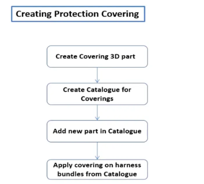
- Open CATIA V5 >> Electrical Part Design.
- Using Define Protection Part
- Select the type as Corrugated Tube.
- Give the Required Parameters (Inner dia, Thickness, Bend Radii( Bend Radii= 1.5 times the OD)
- Click on OK
- After giving the necessary properties save the file.
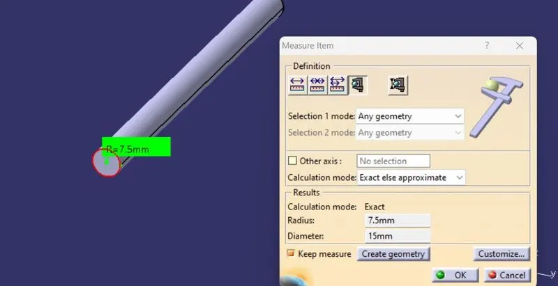
15mm COT
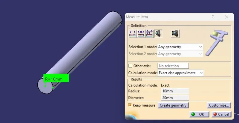
20mm COT
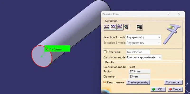
35mm COT
10mm COT
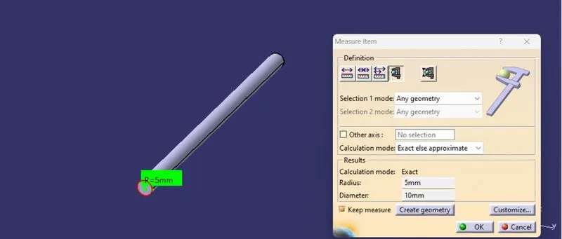
5mm COT