DEVELOPEMENT OF A DOOR TRIM PANEL
DEVELOPEMENT OF A DOOR TRIM PANEL
DOOR TRIM PANEL: The Door Panel covers internal parts like the window regulator,the speaker box,the wiring and the engineering features. It is attached to the sheet metal component of the door. Besides its aesthetic look, it also has many parts such as Door armrest, Bottle holder, Speaker attachment,Map pocket,Lower substrate,Upper substrate etc.Door panels were formerly made of cardboard with an upholstered interior finish of vinyl, leather, cloth, carpet, or other materials for the decorative trim. Modern cars typically have door cards made of plastic component to which all the engineering features are attached and this plastic component is attached to the sheet metal component.
AIM:
To create a Door Trim panel from the inputs of class A surface & By using the Master section as a reference we need to create the engineering features that supports the part body,by following the Standard Design rules.
OBJECTIVES:
- Create a sketch by using positioned sketch and all the sketches should be iso-constrained.
- Ensure proper stree structure such that all the sketches need to be in geometrical sets
- Create a closed part by using thicken command.
- Create the mounting features as per the design rules.
- Creation of Draft analysis for CLass A surface and the final part body.
TOOLS USED:
Most commonly used tools in PART WORKBENCH-
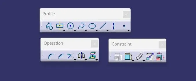
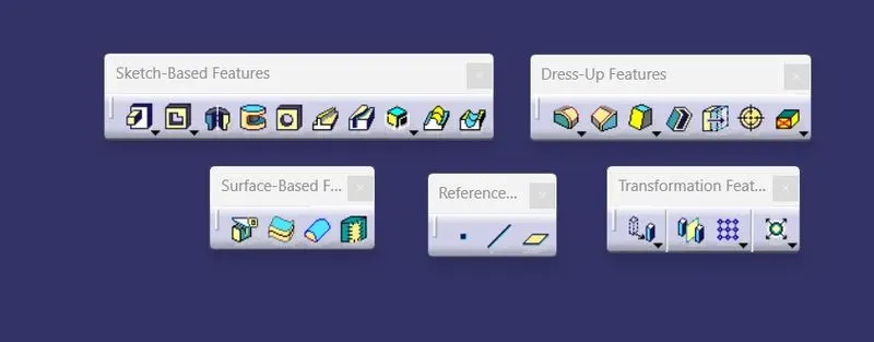
Most commonly used tools in SURFACE WORKBENCH-

GIVEN INPUT OF CLASS A SURFACE:
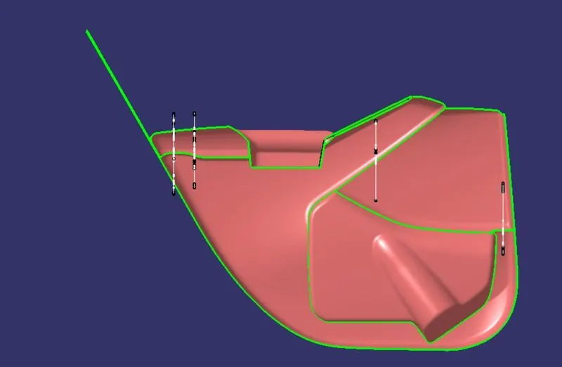
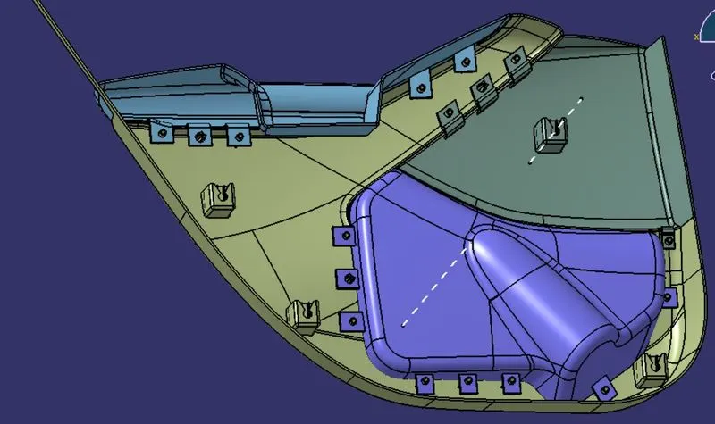
We can see that in the given class A surface we are provided with 4 different parts which we need to work separately to create the CLass B & Class C surface and need to make a part body out of it.Once all the parts are created separately in Catpart we can assemble them together in one CatProduct file and work on the engineering features like Heat stakes,Locators,Dog house,Flanges etc..
The Given input of CLass A surface of Door trim panel consists of:
- Door arm-rest
- Lower substrate
- Map pocket
- Bottle holder
- Master sections representing heat stakes and flanges
1)CREATION OF DOOR ARM REST -
Check the Class A surface by using the boundary command whether it is connected or not.
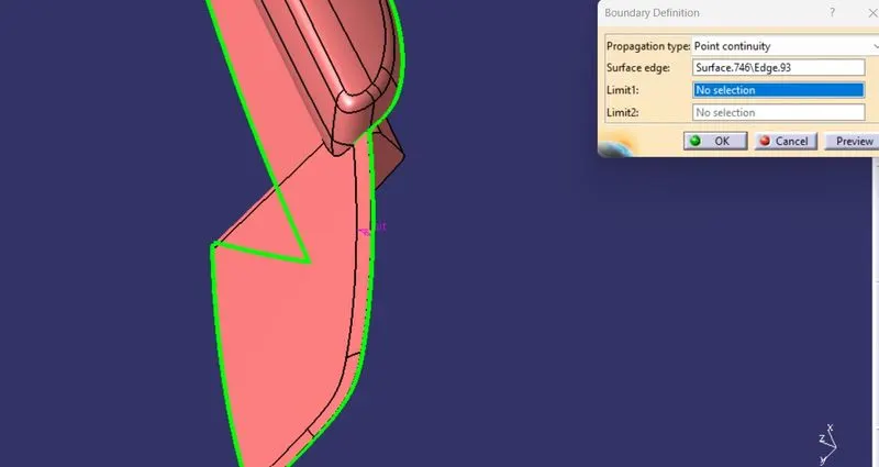
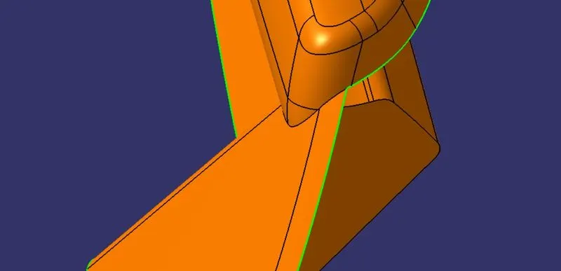
As we can see that there a small opening in the surface of the door arm rest,we need to report it to the CLass A designer,if the problem is resolved it is ok,if not wee need to work on it.
IMPROVING THE CLASS A SURFACE- If the CLass A surface has an issue we can fix it using join command by adjusting the merging distance to 0.09mm.But this 0.09mm of merging distance is to be used only in improving the classs A surface.For CLass B & class C surface we have to use blw 0.001-0.003mm of merging distance.After adjusting the merging ditance now our Class A surface looks good without any gaps so we work on creating Class B & class C surfaces.
TOOLING AXIS CRAETION- Check the given surface completely to identify the location to create the tooling axis,always select the surface which is flat and when viewing from the normal view,ensure all the surface can be visible with that view.
The tooling axis is created such that tha draft analysis can be done by that tooling direction.we have 3 conditions for this
1.With respect to the axis system(x,y,z axis)
2.Normal to surface
3.Bisecting mecthod
If any one condition is satisifed then continue with that condition.
Let us check withthe axis system,extract the flat face and create a point and then line by using point direction method.
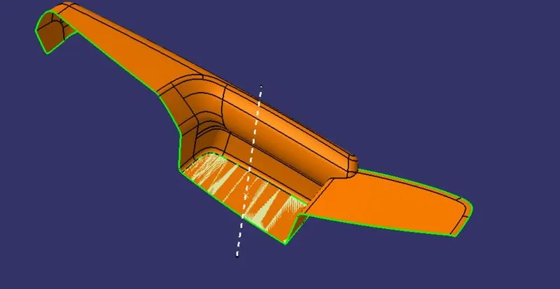
Once the tooling axis creation is completed check the draft anlysis with that tooling axis,if the draft anlysis is going to clear means we can proceed with that tooling axis.
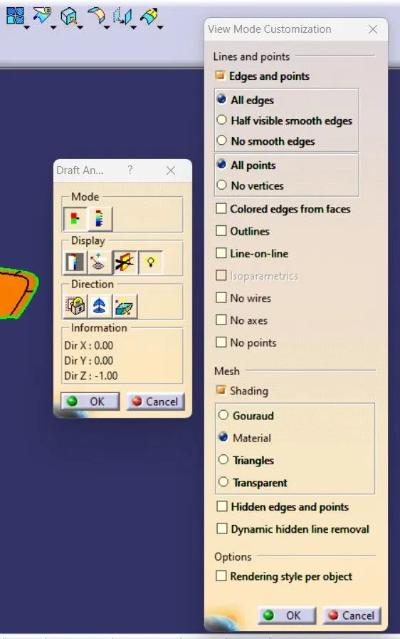
DRAFT ANALYSIS ON CLASS A SURFACE-To perform the draft analysis on the model, firstly we should open customize view parameters and then a dialogue box will be opened ( View mode customization ) and then in that we need to choose the
mode as material.
Then go to insert>Analysis>Feature draft analysis as shown in the fig:
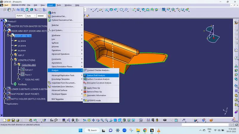
First we need to the align the compass with the tooling axis and then lock it.Now trace the point towards the surface and click on it,the the color changes to red or green now we can flip it,enable the green to be visible.set the draft angle to 3 deg.
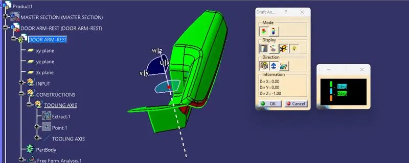
We can see that some faces on the surface are red because it is the problem with the Class A surface,so ourfinal part body can also be same as the CLass A surface at that area.We need to create a ise core tooling axis to clear the draft analysis.So we can proceed with creating the part body.
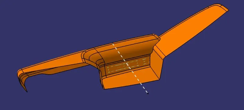
CREATION OF SIDE CORE TOOLING AXIS: Take an extract from th flat surface which is perpendicular to the main tooling axis and create a point and then make a line using point direction method.
SURFACE CREATION-
CLASS B SURFACE: The given Class A surface is to be offseted 2.5mm inwards.When offseted we have observe the patches over the surface which we need to fix them.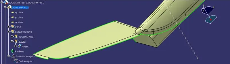
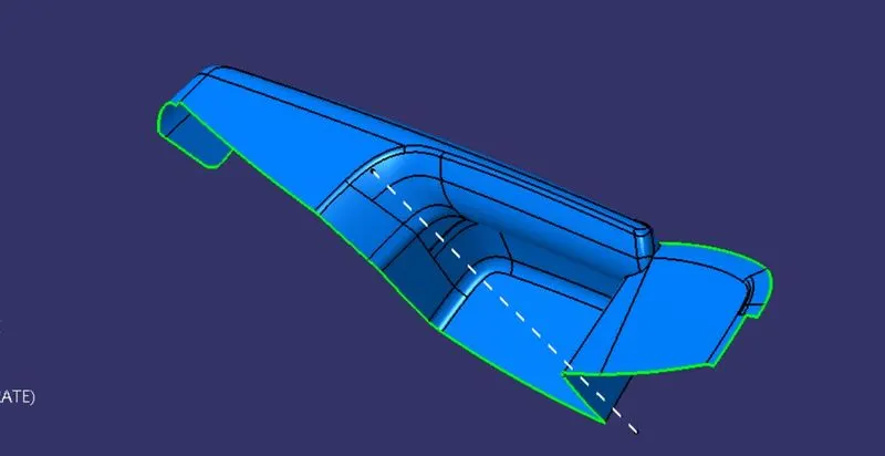
These patches can be fixed by using mutlisection at that area.And we need to use commands like spilt,extrapolate,multisection,join.The below image shows the final B surface.
CLASS C SURFACE: We need to create the sweep patch by patch.In this armrest,the sweep cannot possible on one shot,so we need to make patch by patch by creating a boundary where it is reuired and then creating the sweep.For creating the Class C surface we are going to use two options
1.With reference surface-If the C surface is perpendicular to tooling axis (90 deg)
2.With draft direction-If the c surface is parallel to the tooling axis.(3 deg)
At fillet area we are going to make multisection since thw sweep cannot be made on that area.The final C surface is shown below.
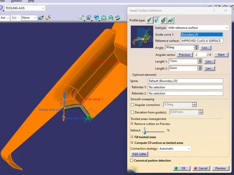
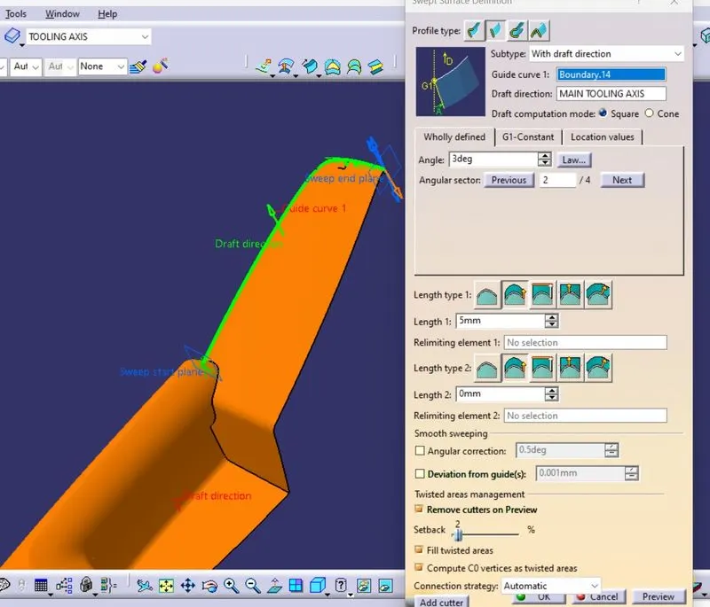
As shown in the above figures we need to apply the sweep command patch by patch since it can not obtain on one stretch.
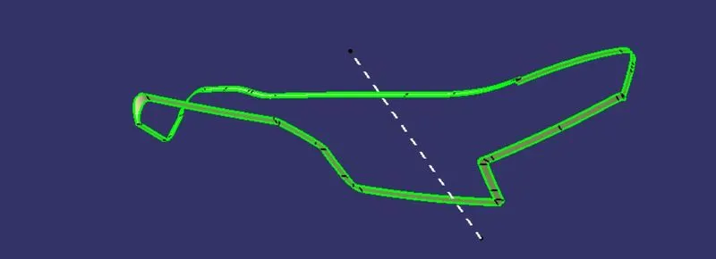
The sweep is be joined with the Class A surface.The final join is to be trimmed with the CLass B surface so th at we can obtain a closed surface.The below image shows the closed surface.
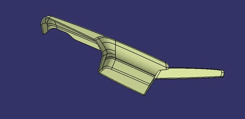
Insert a body goto part workbench and close the surface by using clossurface command.The below image shows the closed part body in different views.
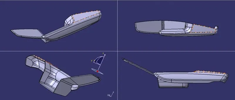
DRAFT ANALYSIS ON FINAL PART BODY: Goto feature draft analysis and check the draft anlysis on the part body.Here we
are going with 2.9 deg draft.And almost all the part body is clearing the draft anlysis.
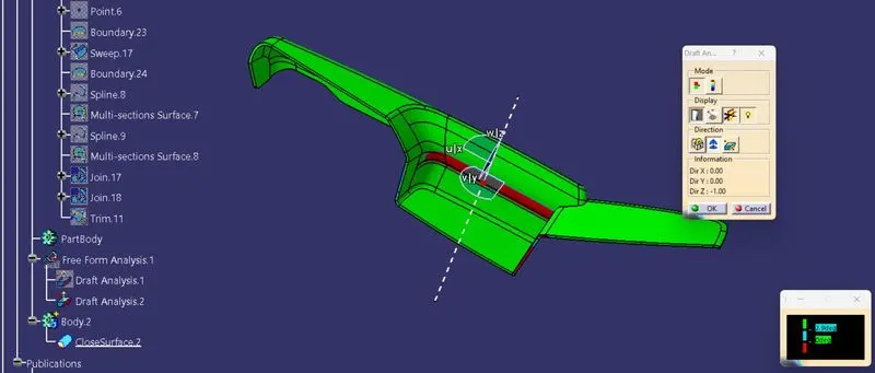
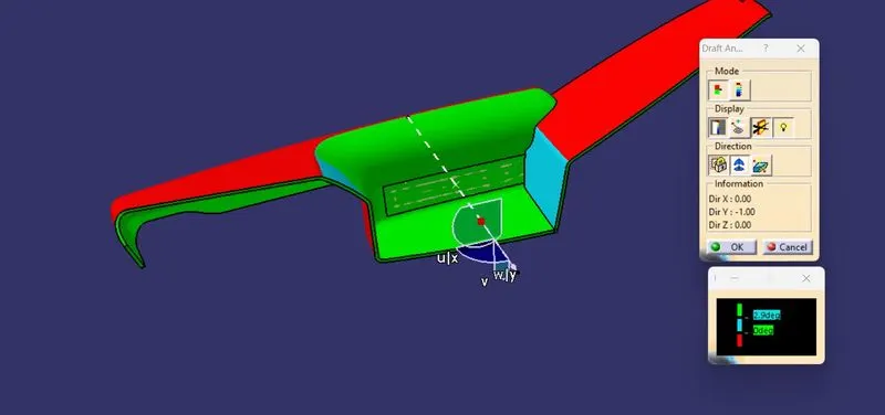
At the area which is not clearing the draft with the main tooling axis we need to create a side core toolingaxis w.r.t it,so that the red color region can be ceared w.r.t to that side core tooling axis.
2)CREATION OF LOWER SUBSTRATE -
Check the Class A surface by using the boundary command whether it is connected or not.We can not find any openings in the lower substrate ,so we can proceed.
TOOLING AXIS CRAETION- Check the given surface completely to identify the location to create the tooling axis,always select the surface which is flat and when viewing from the normal view,ensure all the surface can be visible with that view.
The tooling axis is created such that tha draft analysis can be done by that tooling direction.we have 3 conditions for this
1.With respect to the axis system(x,y,z axis)
2.Normal to surface
3.Bisecting mecthod
If any one condition is satisifed then continue with that condition.
Let us check withthe axis system,extract the flat face and create a point and then line by using point direction method.
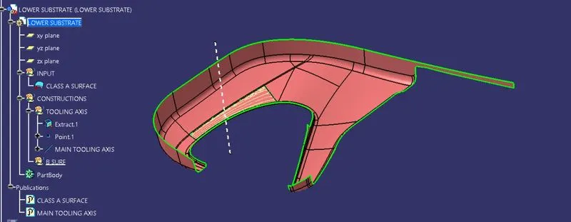
DRAFT ANALYSIS ON CLASS A SURFACE: First we need to the align the compass with the tooling axis and then lock it.Now trace the point towards the surface and click on it,the the color changes to red or green now we can flip it,enable the green to be visible.set the draft angle to 3 deg.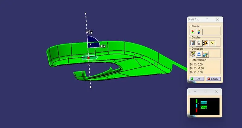
As we can see the draft anlysis is goint to clear hence we can conform with that tooling axis.
SURFACE CREATION-
CLASS B SURFACE: The given Class A surface is to be offseted 2.5mm inwards.We can not find any patches or gaps on the surface so we can extrapolate the B surface to a miminum vlaue so that when trimmed with the A+c surface there will be no issues.The below image shows the final extrapolated B surface .
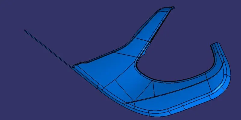
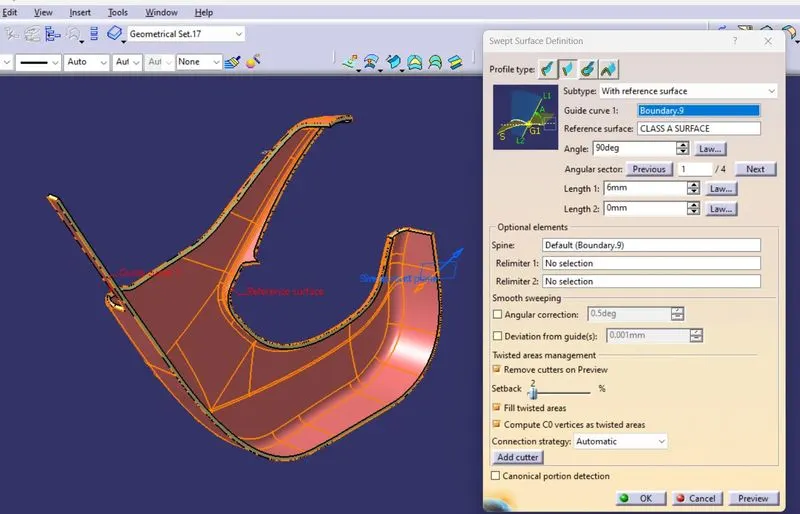
CLASS C SURFACE: We can create the sweep on one shot by creating a boundary.For this lower substrate we are going to use
1.With reference surface method-If the C surface is perpendicular to tooling axis (90 deg).The final sweep is shown below.
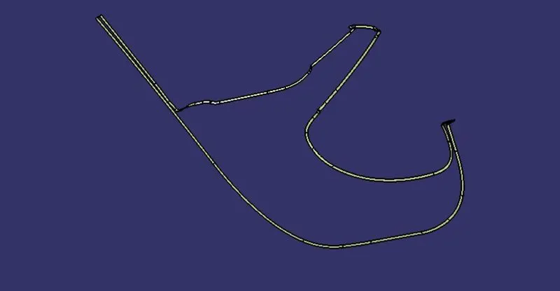
The sweep is be joined with the Class A surface.The final join is to be trimmed with the CLass B surface so th at we can obtain a closed surface.The below image shows the closed surface.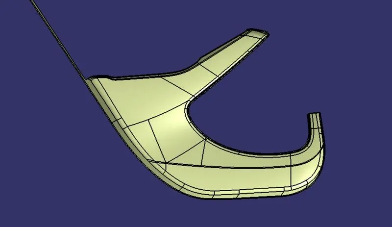
Insert a body goto part workbench and close the surface by using clossurface command.The below image shows the closed part body in different views.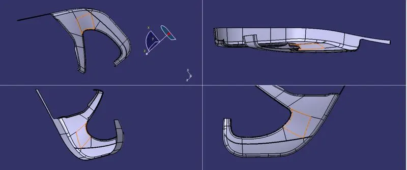
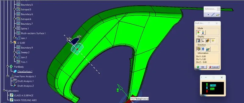
DRAFT ANALYSIS ON FINAL PART BODY: Goto feature draft analysis and check the draft anlysis on the part body.Here we
are going with 2.9 deg draft.
3)CREATION OF MAP POCKET -
Check the Class A surface by using the boundary command whether it is connected or not.We can not find any openings in the MAP POCKET ,so we can proceed.
TOOLING AXIS CRAETION- Check the given surface completely to identify the location to create the tooling axis,always select the surface which is flat and when viewing from the normal view,ensure all the surface can be visible with that view.
The tooling axis is created such that tha draft analysis can be done by that tooling direction.we have 3 conditions for this
1.With respect to the axis system(x,y,z axis)
2.Normal to surface
3.Bisecting mecthod
If any one condition is satisifed then continue with that condition.
Let us check withthe axis system,extract the flat face and create a point and then line by using point direction method.
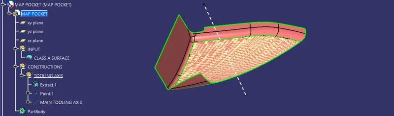
DRAFT ANALYSIS ON CLASS A SURFACE: First we need to the align the compass with the tooling axis and then lock it.Now trace the point towards the surface and click on it,the the color changes to red or green now we can flip it,enable the green to be visible.set the draft angle to 3 deg.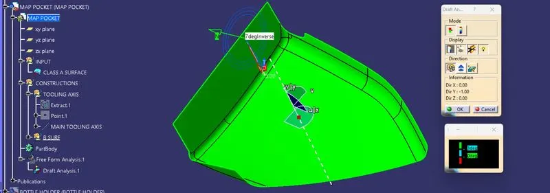
As we can see the draft anlysis is goint to clear hence we can conform with that tooling axis.
SURFACE CREATION-
CLASS B SURFACE: The given Class A surface is to be offseted 2.5mm.We can not find any patches or gaps on the surface The below image shows the final extrapolated B surface .
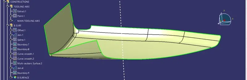
CLASS C SURFACE: We can create the sweep on one shot by creating a boundary.For this lower substrate we are going to use
1.With reference surface method-If the C surface is perpendicular to tooling axis (90 deg).The final sweep is shown below.
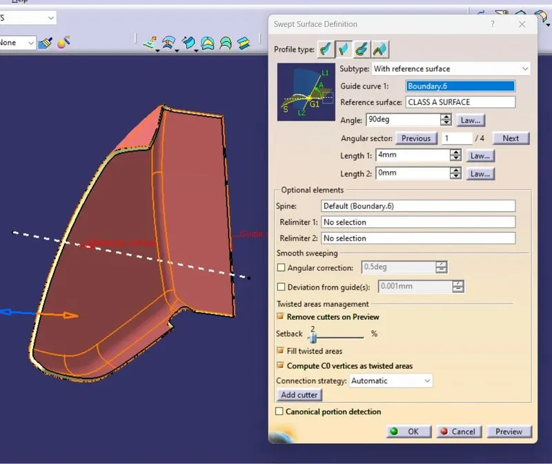
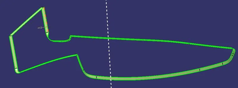
The sweep is be joined with the Class A surface.The final join is to be trimmed with the CLass B surface so th at we can obtain a closed surface.The below image shows the closed surface.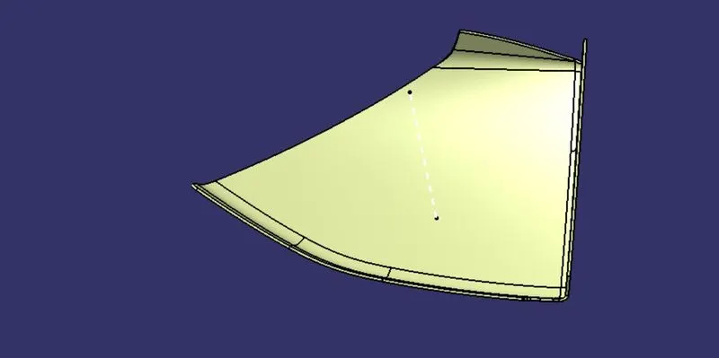
Insert a body goto part workbench and close the surface by using clossurface command.The below image shows the closed part body in different views.
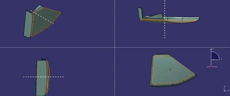
DRAFT ANALYSIS ON FINAL PART BODY: Goto feature draft analysis and check the draft anlysis on the part body.Here we
are going with 2.9 deg draft.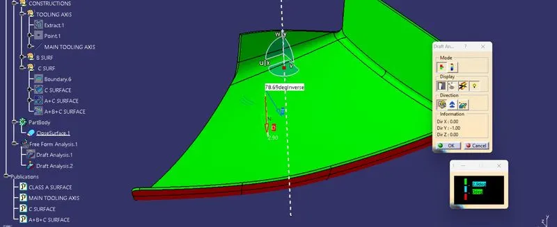
4)CREATION OF BOTTLE HOLDER -
Check the Class A surface by using the boundary command whether it is connected or not.We can not find any openings in the MAP POCKET ,so we can proceed.
TOOLING AXIS CRAETION- Check the given surface completely to identify the location to create the tooling axis,always select the surface which is flat and when viewing from the normal view,ensure all the surface can be visible with that view.
The tooling axis is created such that tha draft analysis can be done by that tooling direction.we have 3 conditions for this
1.With respect to the axis system(x,y,z axis)
2.Normal to surface
3.Bisecting mecthod
If any one condition is satisifed then continue with that condition.
Let us check withthe axis system,extract the flat face and create a point and then line by using point direction method.
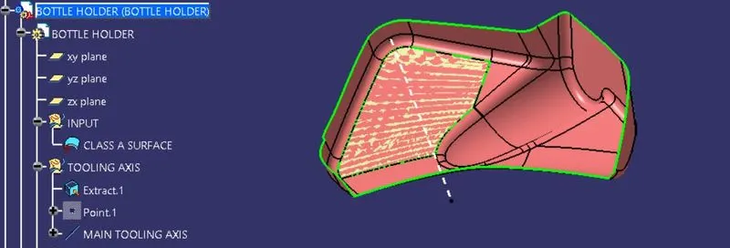
DRAFT ANALYSIS ON CLASS A SURFACE: First we need to the align the compass with the tooling axis and then lock it.Now trace the point towards the surface and click on it,the the color changes to red or green now we can flip it,enable the green to be visible.set the draft angle to 3 deg.
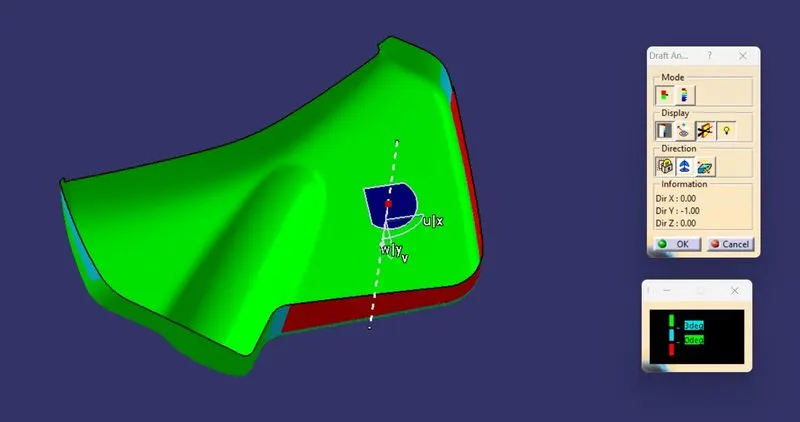
We can see that some area are not clearing with the draft analysis,but this is the problem with the CLass A surface.
SURFACE CREATION-
CLASS B SURFACE: The given Class A surface is to be offseted 2.5mm.We can not find any patches or gaps on the surface The below image shows the final extrapolated B surface .
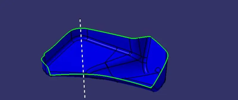
CLASS C SURFACE: We can create the sweep on one shot by creating a boundary.For this lower substrate we are going to use
1.With reference surface method-If the C surface is perpendicular to tooling axis (90 deg).The final sweep is shown below.
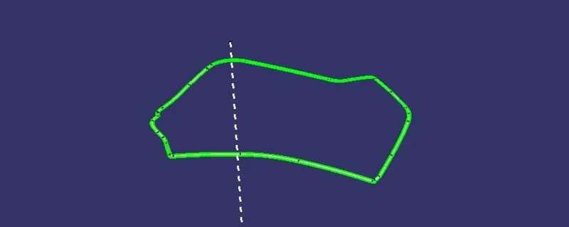
The sweep is be joined with the Class A surface.The final join is to be trimmed with the CLass B surface so th at we can obtain a closed surface.The below image shows the closed surface.
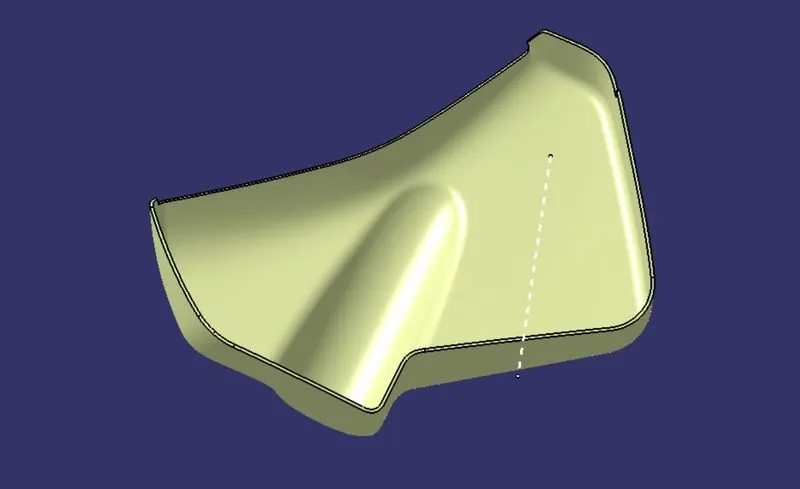
Insert a body goto part workbench and close the surface by using clossurface command.The below image shows the closed part body in different views.
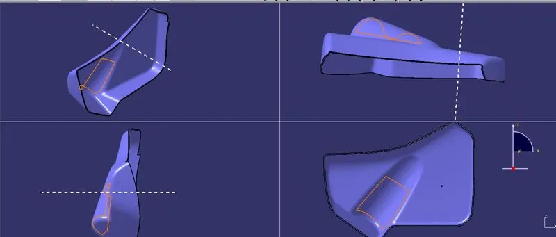
DRAFT ANALYSIS ON FINAL PART BODY: Goto feature draft analysis and check the draft anlysis on the part body.Here we
are going with 2.9 deg draft.
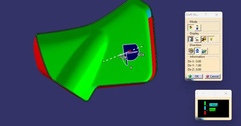
Since it is the problem with the class A surface,even if we tried to decrease the draft angle also we cannot get the green color at that area ,so it need to be reported to Class A design engineer.
CREATION OF ENGINEERING FEATURES:
1)HEAT STAKES-
Heat stakes are mainly known as thermoplastic staking, it is the process of joining two dissimilar metals or non-metals together.In general thermal stacking is an assembly method that uses the controlled melting and reforming of plastic stud or boss to capture another plastic or metal component of an assembly in place.
As in this assmbly the lower substrate is the sutable part to create the heat stakes.so consider the lower substrate and cretae a positioned sketch over the given mastersection area.Create a point by using between method and create a sketch using the master section such that the outer dia and inner dia as 7.5mm and 4.5 mm.
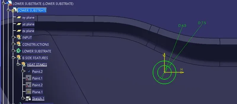
exit the sketch and then pad it to the required height as in the mastersection.We need to apply a draft of 0.5 deg to the faces w.r.t the main tooling axis.
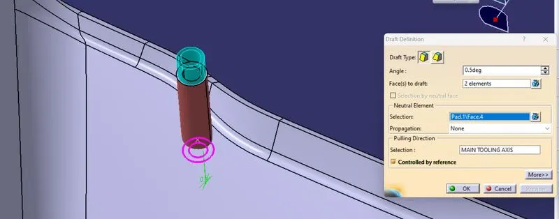
We need to provide minimum fillet to the top face.
The heat stakes are to be provided with the RIBS.The ribs provide sufficient support to the heat stakes so that we need to create the ribs according to the design rules.Provide 0.5 deg draft to the ribs and 0.25 fillet radius.We can pad the ribs by providing a thickness of 1mm and then using boolean operations it cn be removed from the heat stake body.
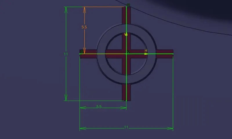
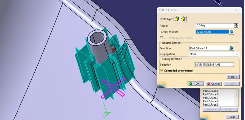
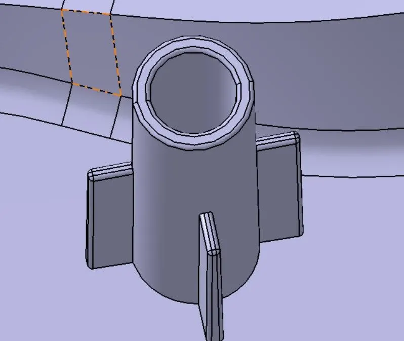
We can translate the heat stake wherever it is need by using point to point method and Maintain a 50mm minimum distance between two heat stakes .
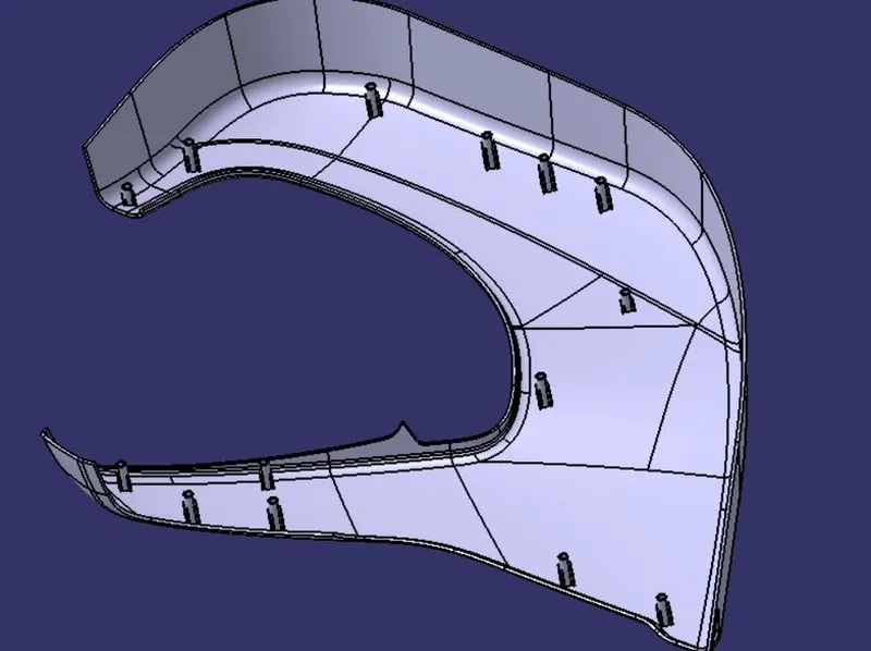
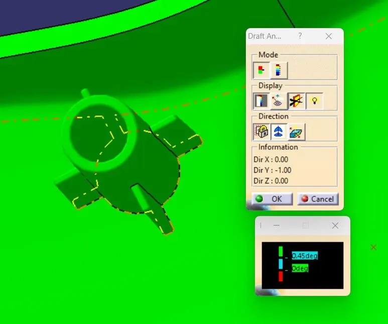
Draft analysis on heat stake:
2)LOCATORS-
Create a point and make a positioned sketch over it as per the design rules shown in the fig.The length os the locator is to be minimum 12 to 15mm but in our sketch it is only 10mm due to the length os the locators is merging with the fillet os the lower substrate and makes sink marks over there,so to avoid the sink marks i have reduced the length.
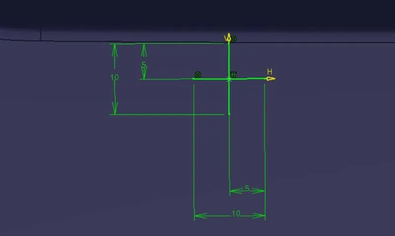
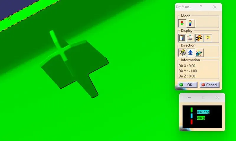
By using pad command it can be extruded,THe height of the locators must be 1 or 2mm more than the height of the heat stakes.Draft the locator for minimum of 0.5 degree .Add Chamfer of 3mm on every edges and add 3 mm fillet to it.Add 0.25 mm fillet to all faces .Assemble all the 4-way locators to one part body and then using boolean opearations,union trim with the lower substrate.
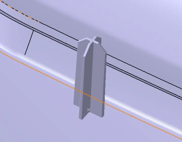
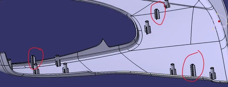
Draft analysis on the locator pin:
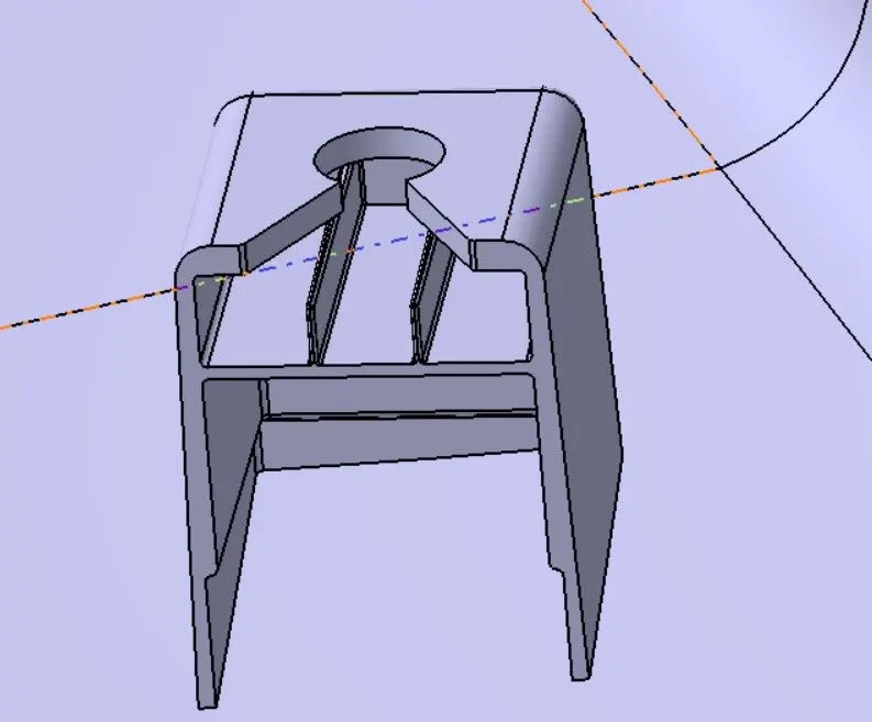
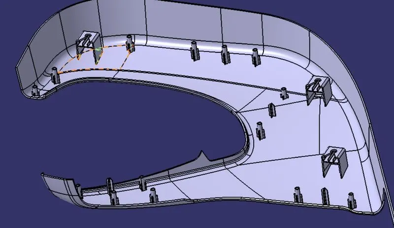
3)DOG HOUSE-
Extract the flat surfaceon the lower substrate and create a point on it and then create a plane using parallel through point and then create a positioned sketch over it.
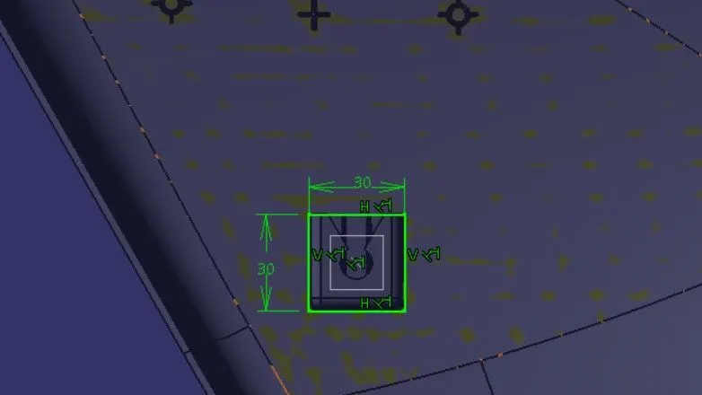
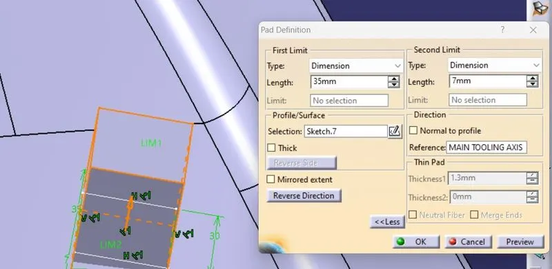
We can pad it to a height of required dimensions and provide the direction as the main tooling axis so that it will clear with the draft analysis.
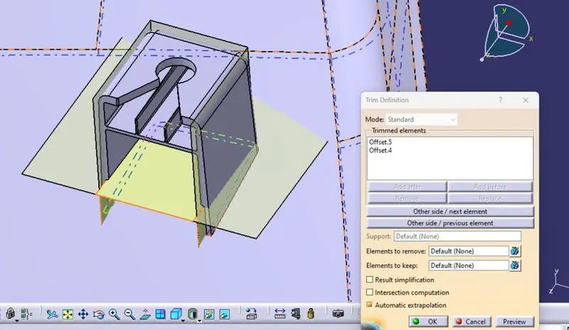
By using shell command give a thickness of 2.5mm on the face side of the dog house.Provide a draft of 1.5deg to the outer faces of the dog house and add fillets to it.
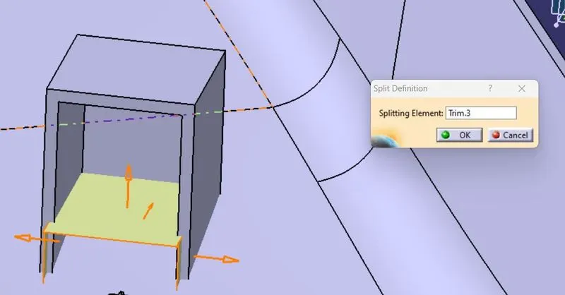
For creating the C portion,take a line and extrude it and trhen offset it to 6mm as it can be 3-6mm.By using multiple extract command take the inner 3 portions and then extrapolate and then offset them to 1mm as the C must be 40%more or less.
SPilt the obtain trim with the part body we may obtain the C portion as required.
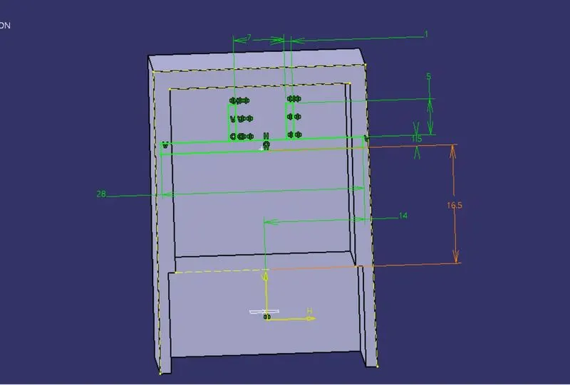
We nee to the rib portion in the dog house for need create a sketch as shown in the fig.
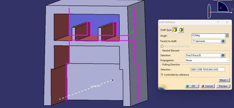
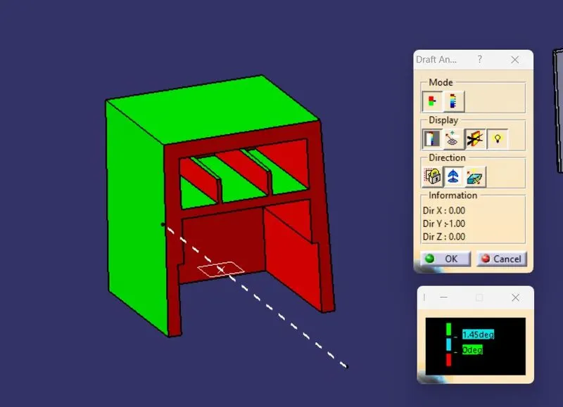
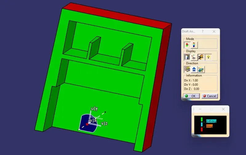
Exit the sketch and pad it.We must have a side core tooling axis to clear the draft on the inner portion of the dog house.Create a line which is perpendicular to the main tooling axis.And provide draft to the inner portion and add fillets to it.
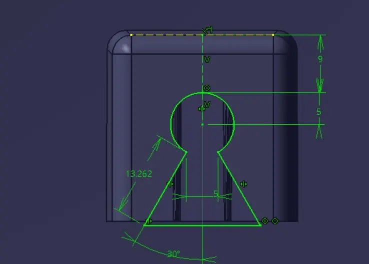
For inserting the push pin over the dog house we need a sketch which is shown below.
Final DOG HOUSE
Draft analysis on DOG HOUSE w.r.t MAIN TOOLING AXIS-
Draft analysis on DOG HOUSE w.r.t SIDE CORE TOOLING AXIS-
4)FLANGE CREATION:
We neeed to create the flanges which holds the heat stakes and the locators.We can take the reference of the flange creation from the master section.Add fillets to it.place the flanges wherever there are heat stakes and locators are placed by using point to point translation.
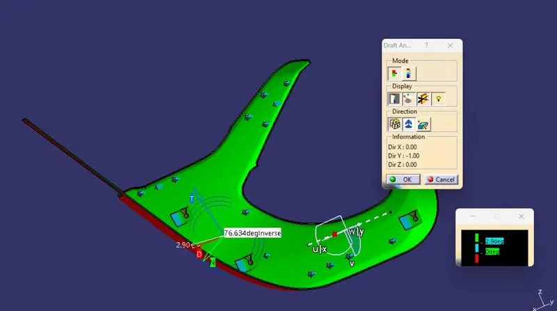
Once the engineering features are done we need to check draft analysis along with the part body.
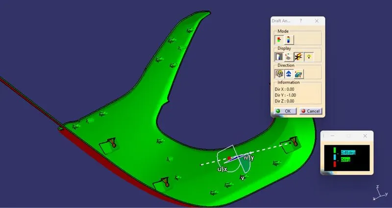
Lower subsrtate draft analysis w.r.t main tooling axis,
Since the main part body is provided 3 deg draft the enginnering features are not clearing with it as we have provided them with 0.45 deg draft.
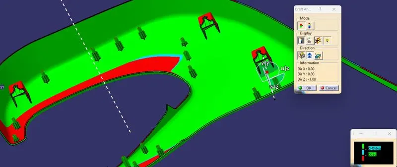
The dog house inner portion can be cleared with side core tooling axis.
Draft analysis on map pocket:
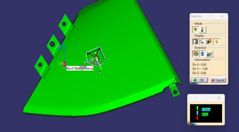
Draft anlysis on bottle holder:
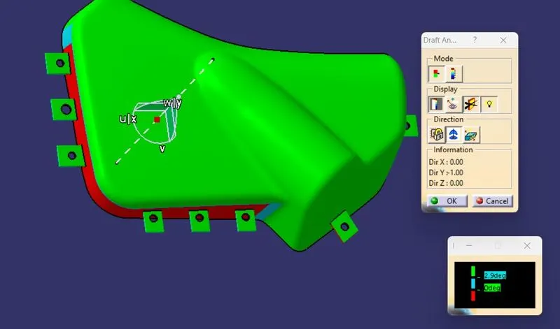
Draft analysis on door armrest:
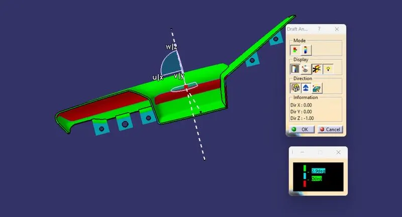
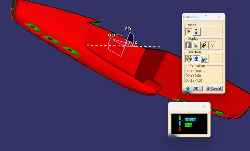
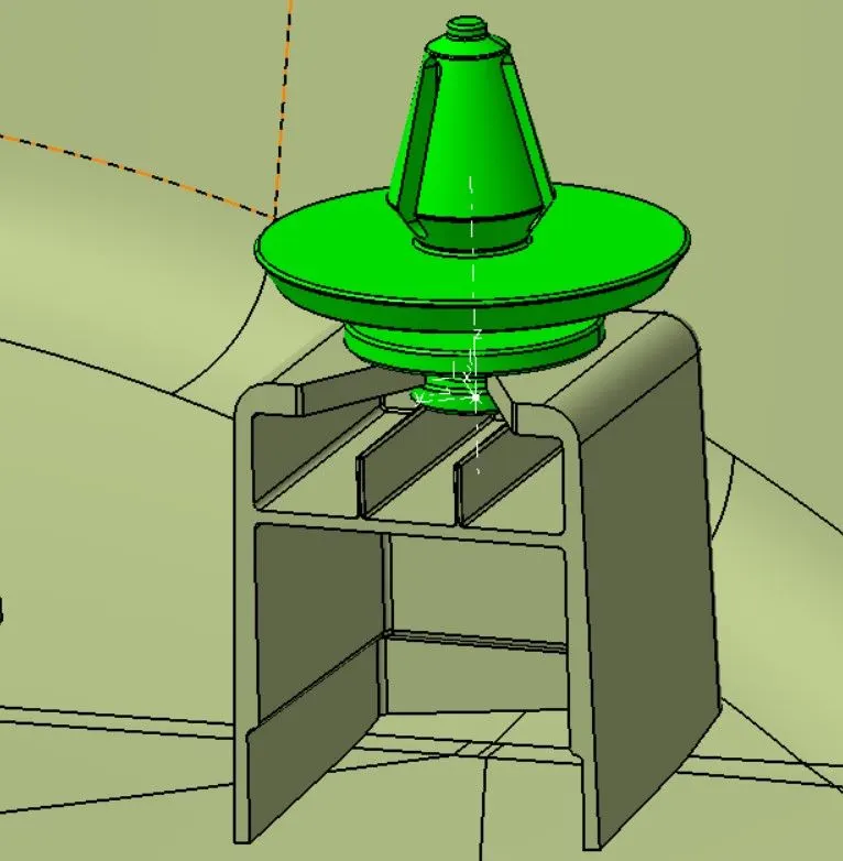
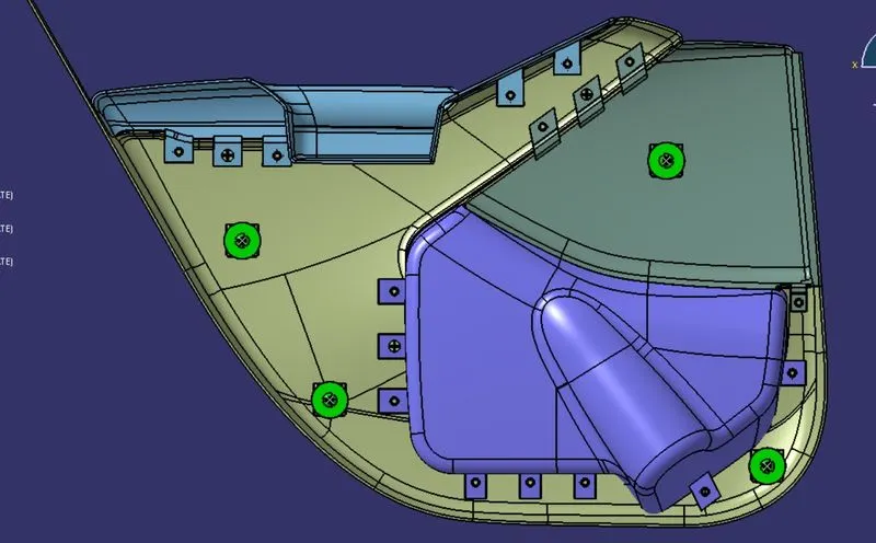
We need to attach the push pin which is given to us with the part body .so that we need to work on assembly workbench.
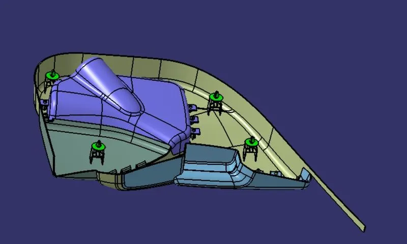
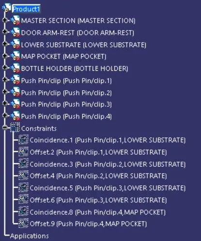
Goto assembly workbench and attach the push pin with the dog house by using coincidence(give axis to axis coincidence) and offset constraints
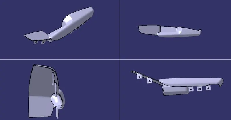
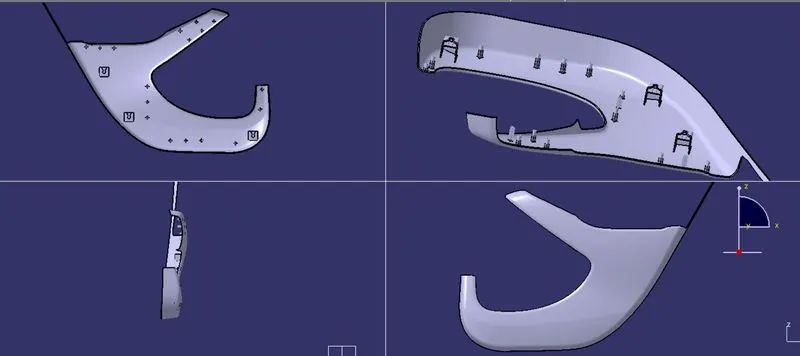
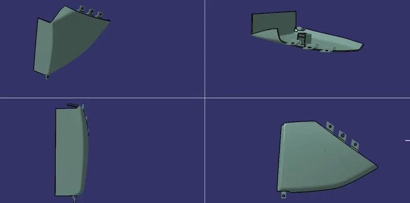
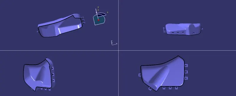
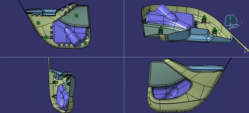
VARIOUS ORIENTATIONS OF PART BODIES:
1-DOOR ARMREST
2-LOWER SUBSTRATE
3-MAP POCKET
4-BOTTLE HOLDER
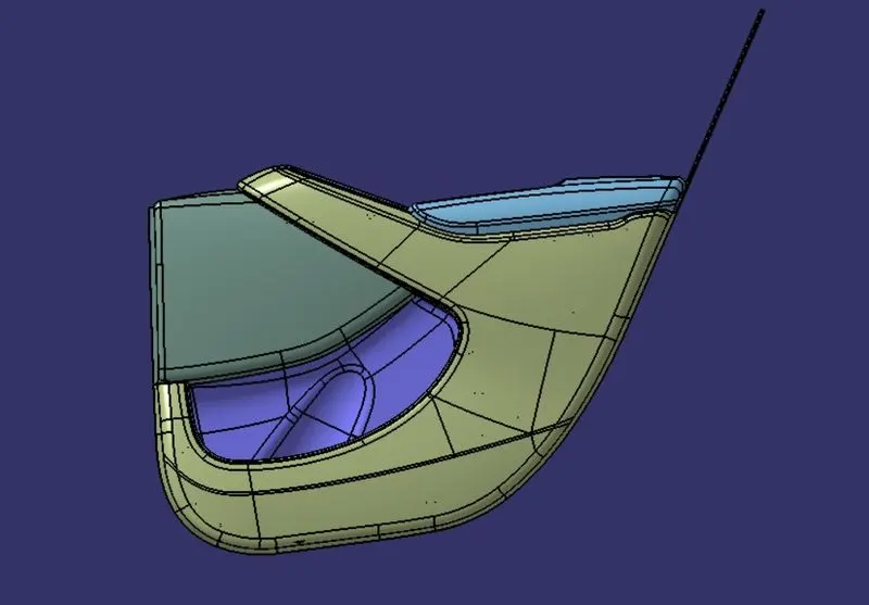
FINAL ASSEMBLED MODEL OF DOOR TRIM PANEL
APPLYING MATERIAL:
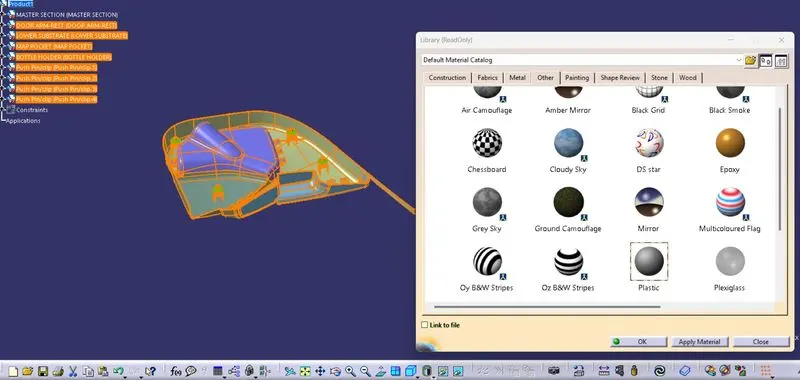
We can apply material to our part body by using apply material command.select all the part bodies(door armrest,lowersubstrate,map pocket,bootle holder and pushpin)and click on plastic and apply material then our part body is having the plastic material.
SInce most of the parts of the door trim panel are made up of plastic material we can use plastic material to our component.
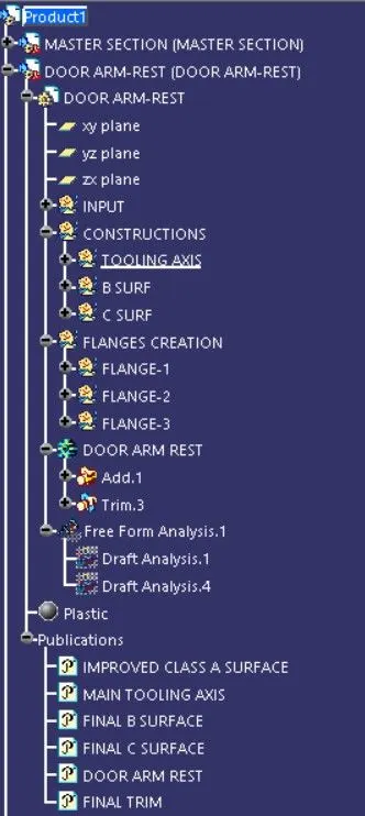
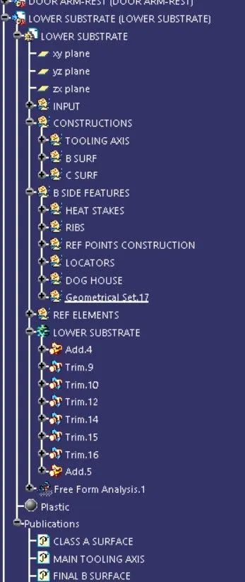
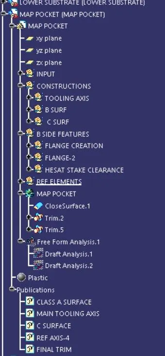
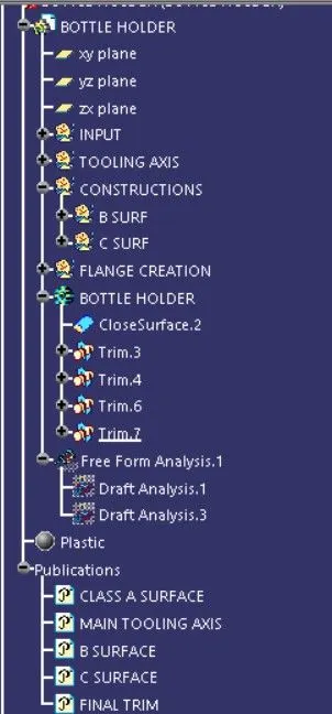
TREE STRUCTURE:
CONCLUSION:
Thus the Door trim panel is created by using the given CLass A surfaces and Mastersection provided as per the Design rules.