Core & Cavity Design
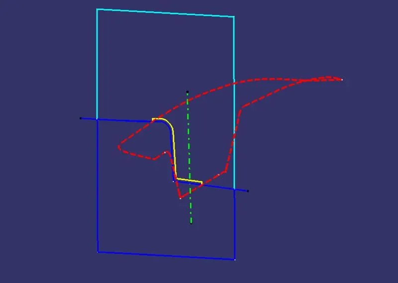
TOOLING AXIS: For creating the tooling axis ensure proper direction for it,for that check the given CLASS A SURFACE in all the directions.By looking into it we can say that z axis is the best suitable direction.Create a dummpy tooling axis by creating a point on the surface of the base by extracting it.Create an axis system at that point and make a sketch on yz plane.Intersect the 3d surface with that point and it craetes and intersection line along the surface.Create 2 lines on the sides of the curves with line command and then make a bisceting line which bisects the created line 1 and line 2.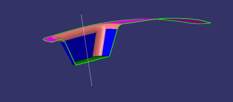
similarly create a sketch 2 on zx plane and intesect the 3d surface with the sketch.Draw a line paralle to the axis and craete a line with 6 deg to the previous line.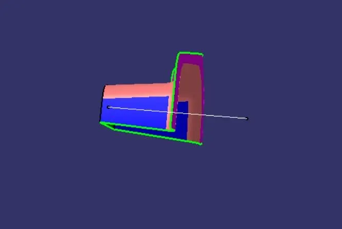
Now create a bisecting line which bisects the yz plne line and zx plane line.The final obtaining line is the tooling axis for the given switch bezel.Ensure that by viewing the tooling axis we can complete the whole sketch with it.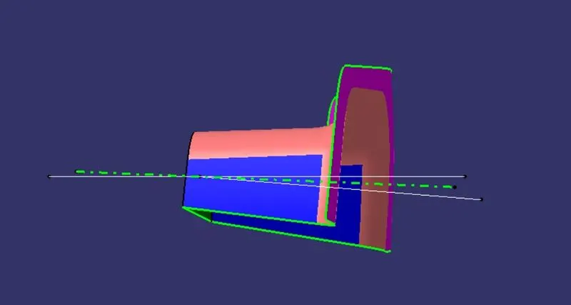
DRAFT ANALSYIS: Select Feature draft analysis command and goto mode options which shows 3 colors(blue, red,green).The green is preferable and set the draft angle to 3 deg.Then goto display option and click on analsyis under running point and check the angles on all thesides os the surface,and goto direction option selection compass and drag it into the tooling axis and fit in it such that the w face should coincide with the tooling axis.If the surface is in blue color change it to green by using flip option in the directions.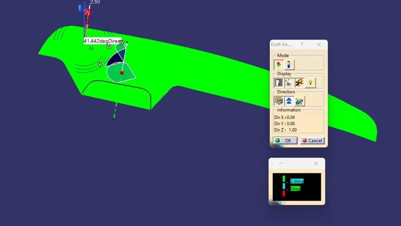
The final draft analysis on switch bezel is shown below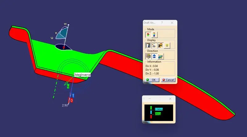
PARTING SURFACE CREATION: The parting surface is the intersection between the core and cavity block.For creating the parting surface extrapolate the class A surface and then trim the extraolate with the final join of class A+ C.it is then intersected with the parting line so that we can obtain the parting surface.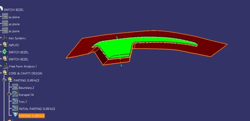
PARTNG LINE: It splits the core and cavity with each other.It is the intersection between the parting surface and the surface of the component.The red color dotted line is the parting line shown below.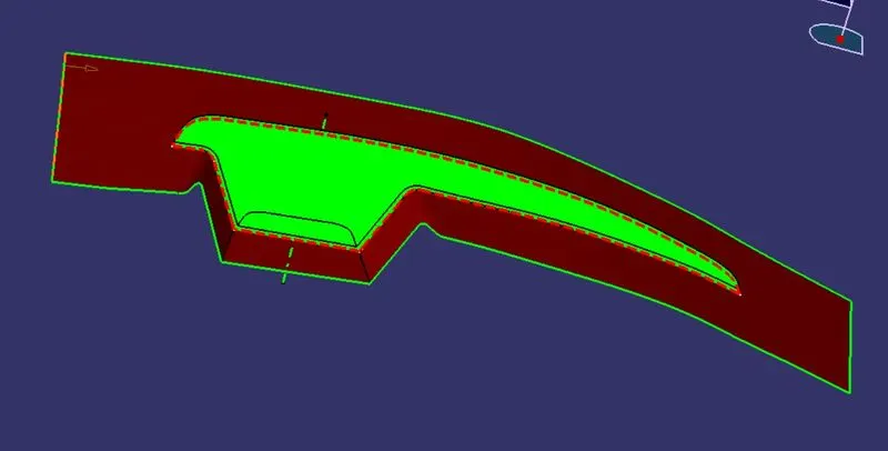
Core and Cavity design:Now we need to create the core and cavity one by one.The core block has the projection od the component whereas the cavity block has the depression of the component.
Core creation-We need make a sketch of rectangle on the surface by selecting the axis system.The sketch must be inside the parting surface.extrude the rectangle by using the tooling axis as the direction. Now trim the upper surface of the extrude with the parting surface.And then by using fill command close the surface of the upper part.Join the fill and the trim part.Goto part workbench and then close the surface by using close surface.we can obtain the closed body of the core.It can translated so that the inner cmponent may be clearly visible.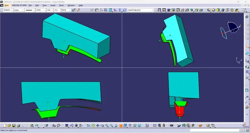
Cavity creation-similarly by using the extrude of previoulsy used sketch ,trim the lower surface with the parting surface,and then by using fill ommand close the surface of the lower part.join the fill and trim by using join commandclose teh surface by using close surface command.It can also be translated to a minimum distance .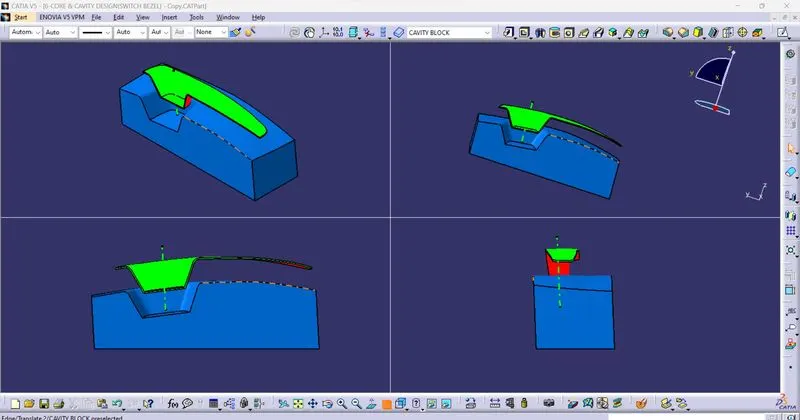
The core and cavity in different views is shown below,we can adjust the translation so that we may clearly see the
comoponent core block and cavity block.
.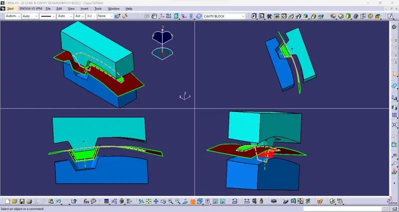
The intersection is to be made for the axis system with respect to the core block,cavity block,parting surface,switch bezel,so that it can be clearly identifed where the component is filled by the material.