Wiring harness design in CATIA V5
AIM:To define the given components as Electrical Connectors using Electrical Part design Workbench & to define all the necessary properties to the Connectors & Clip.
INTRODUCTION:
WIRING HARNESS:A wiring harness is an organised set of wires,terminals & connectors that runs throughout the entire vehicle & transmit the information and electrical power thereby playing a cruical role in connecting a vareity of components.The wirng harness is a combination of both mechanical & electrical data.
WIRING HARNESS ROUTING:The best design for wiring harness routing is the distance we need to keep the wiring harness from the different components of the vehicle system such as exhaust,coolant lines,heater lines etc..
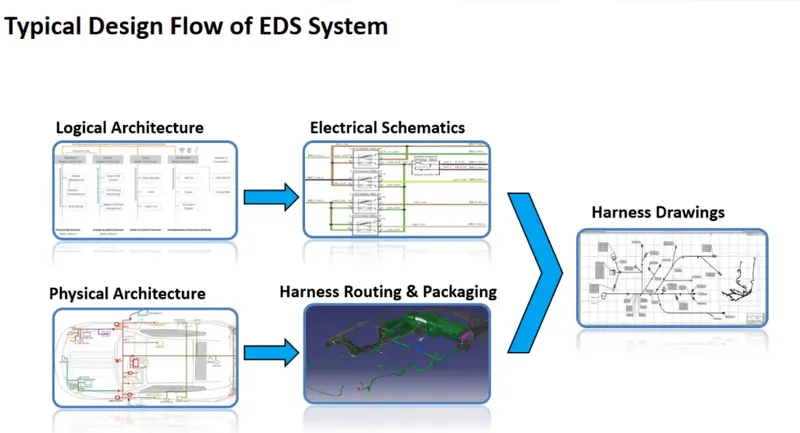
ELECTRICAL DISTRIBUTION SYSTEM(EDS):EDS basically deals with
- Physical &logical architecture.
- Schematic development.
- Power distribution.
- Wiring harness design.
- Wiring harness component design.
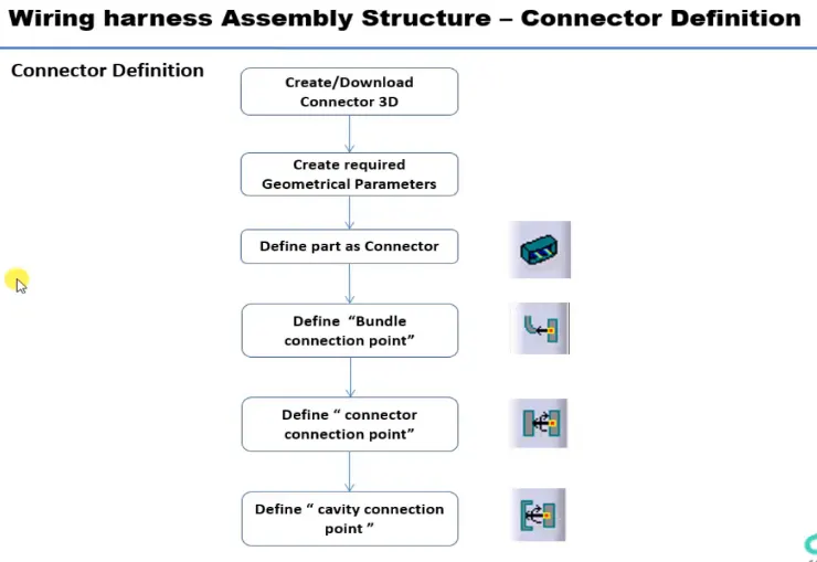
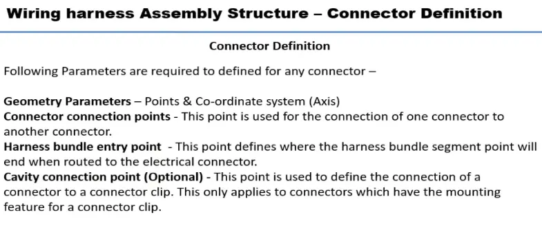
CONNECTORS:An electrical connector,is an electro mechanical device used to join electrical termination & create an electric circuits.
The connectors that are used in this challenge are:
1.Deutsch DT06 – 08SA ( https://www.te.com/usa-en/product-DT06-08SA.html)
- First download the component from the link.
- Provide the required geometrical parameters like points,axis system.
- The points are to be created by using point>>between command at the bundle entry point and the connector connection point.
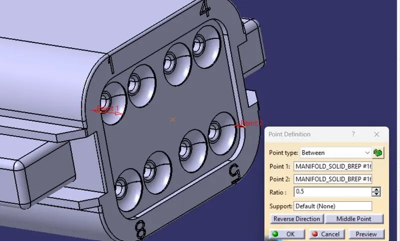
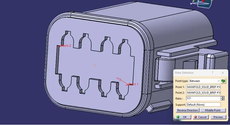
- Create an axis system at the connector connection point.
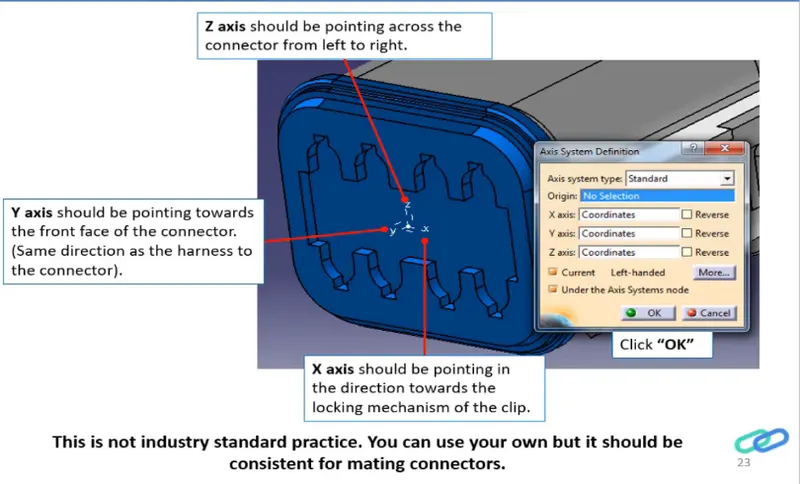
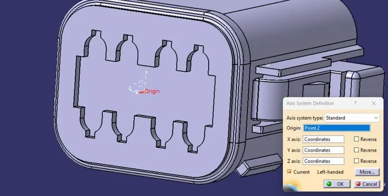
- Now Switch to Electric Part Design and define the part as connector in catia v5, give no. of termination as 8 because we have 8 entry points for wire.
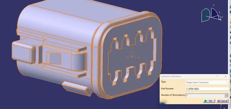
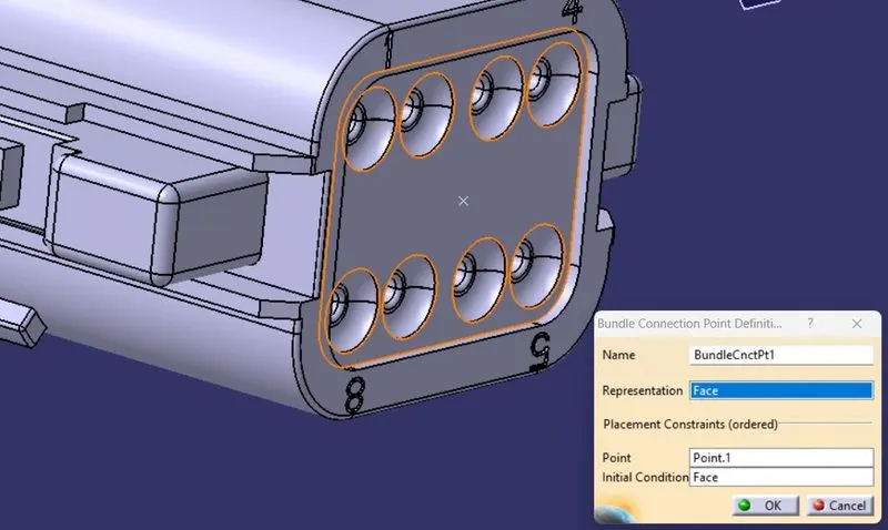
- Define Bundle connection point.
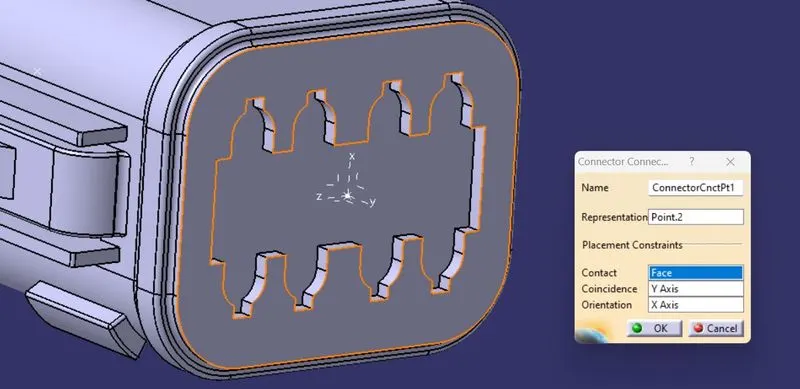
- Define connector connection point.
2.Tyco 174357-2 (https://www.te.com/usa-en/product-2-174357-2.html?source=header-match)
- First download the component from the link.
- Provide the required geometrical parameters like points,axis system.
- The points are to be created by using point>>between command at the bundle entry point and the connector connection point.
- Create cavity connection point and then axis system for the cavity connection.
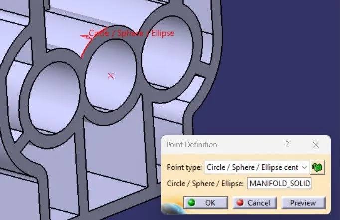
- Create an axis system at the connector connection point.
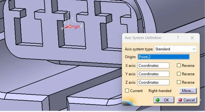
- Create an axis system at the cavity connection point.
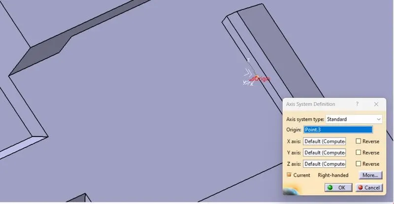
- Now Switch to Electric Part Design and define the part as connector in catia v5, give no. of termination as 8 because we have 3 entry points for wire.
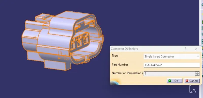
- Define Bundle connection point.
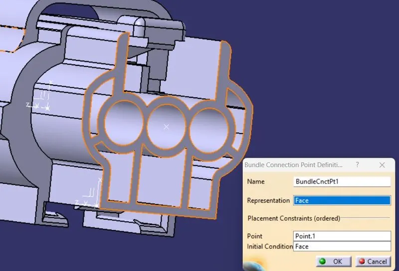
- Define connector connection point.
- Define cavity connection point.
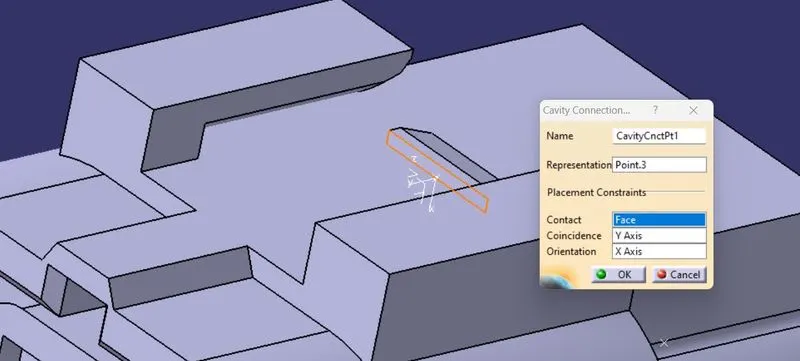
3.Tyco 85229-1 – (https://www.te.com/usa-en/product-85229-1.html?q=85229&source=header)
- First download the mounting clip from the link.
- Provide the required geometrical parameters like points,axis system.
- The points are to be created by using point>>between command at the bundle entry point and the connector connection point.
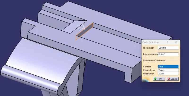
- Create cavity connection point and then axis system for the cavity connection.
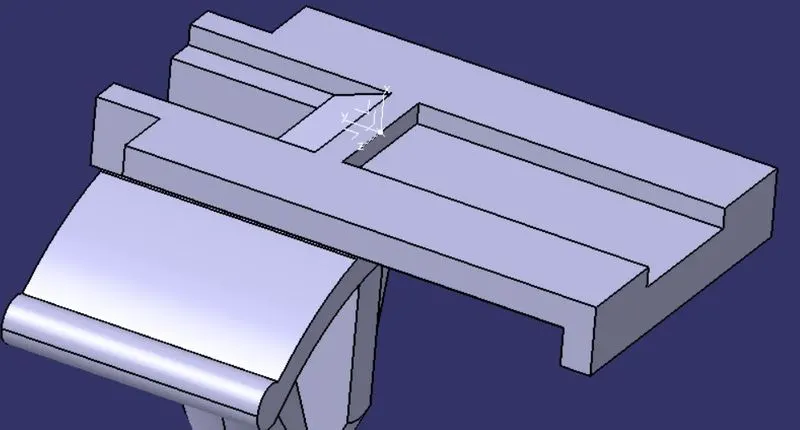
- Now Switch to Electric Part Design and define the part as cavity.
ELECTRICAL ASSEMBLY DESIGN:
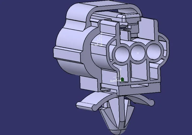
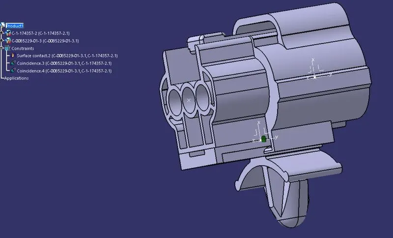
- Switch to electrical assembly design and copy the connector 2 i.e Tyco 174357-2 and paste it,similarly copy the clip i.e Tyco 85229-1 and paste it.
- Select "Connect electrical devices" command and select the cavity ad then connector to fix them.
CONCLUSION:
Given connecters and clips are successfully electrically defined and assembled the connecter and clip.