Attachment Feature Creation (Ribs & Screw Boss)
The given CLASS A SURFACE is to be checked properly,for making sure the given surface has no gaps.Once if it confromed ,then go for tooling axis creation , by using boundary.If any gaps we need to work on it and not we can continue with creating the,tooling axis,intial draft analysis and then b surface.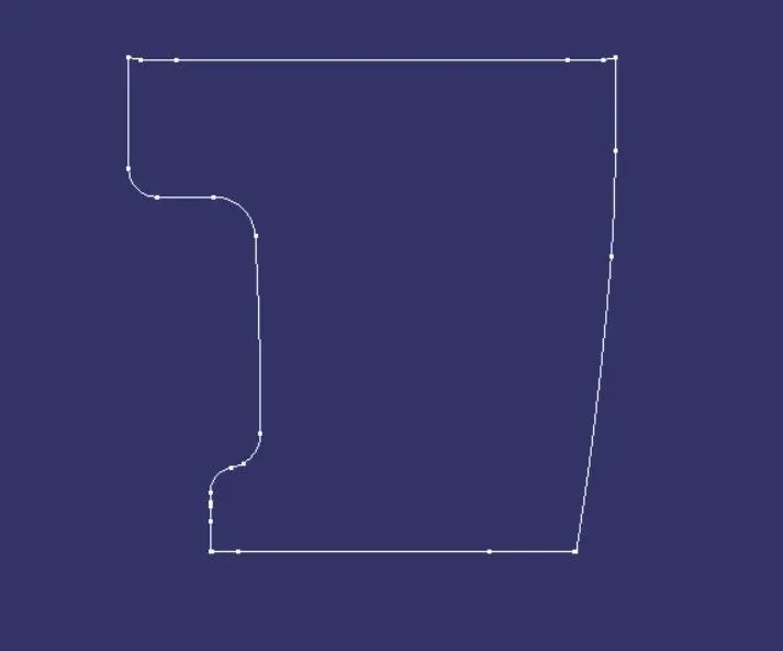
Tooling axis creation:check the given surface completely to identify the location of tooling axis,always select the surface which is flat and when viewing from the normal view ensure all the surface can be completed with that view.
The tooling axis is created such that tha draft analysis can be done by that tooling direction.we have 3 conditions for this
1.with respect to the axis system(x,y,z axis)
2.normal to surface
3.bisecting mecthod
If any one condition is satisifed then continue with that condition.
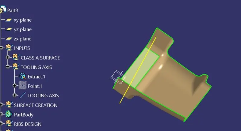
In this challenge,let us consider the axis system,take the given surface and extract the flat surface and then make a line by using point direction method,lets check the draft analysis with the tooling direction.In this case the draft analysis is going to clear ,so we can name name the line as tooling axis.In this Below fig the surface i extracted is shown clearly and made the tooling axis.
.
Bisecting method:lets us check with this method also.we need to us boundary commadn over the edge of the part and make lines by suing point to point mehtod.when two lines are created at the ends use bisectign method and make a bisecting line by them.but in this case the draft analysis is not going to clear so we go for axis system tooling analyisis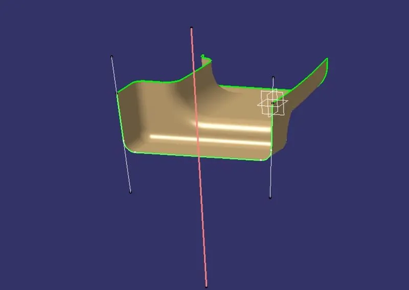
DRAFT ANALYSIS: Once the tooling axis is completed then we can proceed with the draft analysis of the given surface.For that open Feature draft analysis and select modes to set proper mode options which shows 3 colors(blue, red,green).The green is preferable and set the draft angle to 3 deg.Then goto display option and click on analsyis under running point and check the angles on all thesides os the surface,and goto direction option selection compass and drag it into the tooling axis and fit in it such that the w face should coincide with the tooling axis.If the surface is in blue color change it to green by using flip option in the directions.Initial darft analysis of the class A suraface is shown below. in this case we take draft anle as 2.9 deg.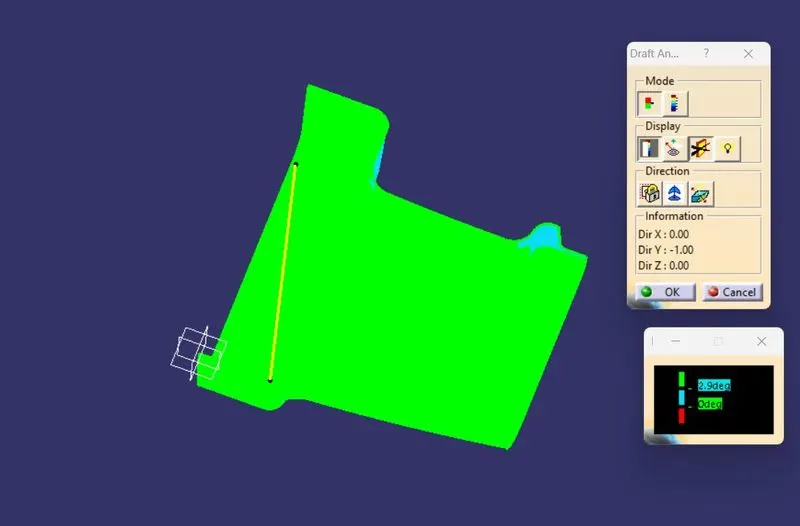
final draft analysis is hown below.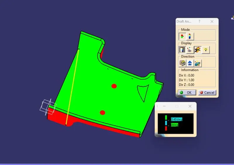
CLASS B SURFACE CREATION:For creating the B surface,the given A surface is offseted to 2.5mm as given.we can observe a small patchor a gap on the surface.which we are going to work on it.These pathes can be cleared by using multi section surface,weare going to create 3 boundary over the patchand fill by sisng multi section surface command.the surface is to be extrapolated all around by a minimum thickness so that when trimmed with A+C surface there will be no issues.This is the final B surface.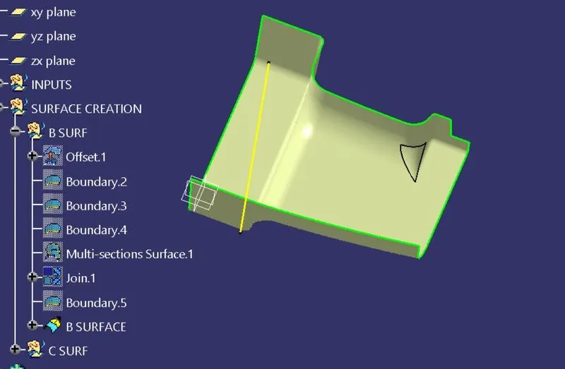
CLASS C SURFACE CREATION:Once the B surface is created we need to work on C surface.The c surface can be created part by part from the given class A surface.For creating the Class C surface we are going to use two options
1.with reference surface-if the c surface is perpendicular to tooling axis (90 deg)
2.with draft direction-if the c surface is parallel to the tooling axis.
At fillet areas we are going to use multi section surface so that ther be will be no issues.all the sweep part sare joined at the end as one surface.ensure proper length while creating the c surface so that it must overlap with the b surface.
The final c sruface is shown below.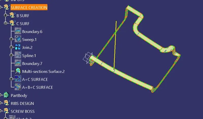
The C surface is joined at 2 two areas one is the join 2 and the other id the mutli section wich we separtly created.and the the whole surface is joined with A surface and then trimmed with the b surface.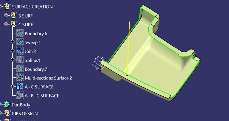
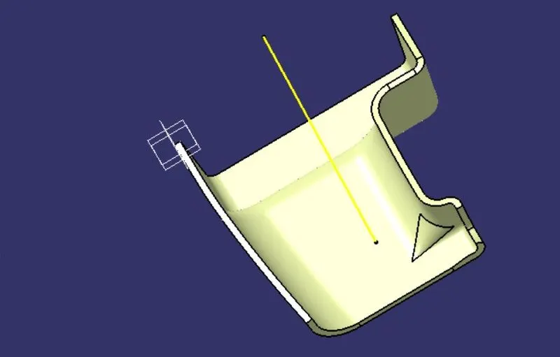
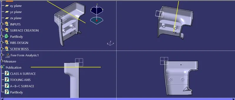
Onve it completed we can go dor creating the b side features which gives support tothe part body ,they are ribs and screw bosses.
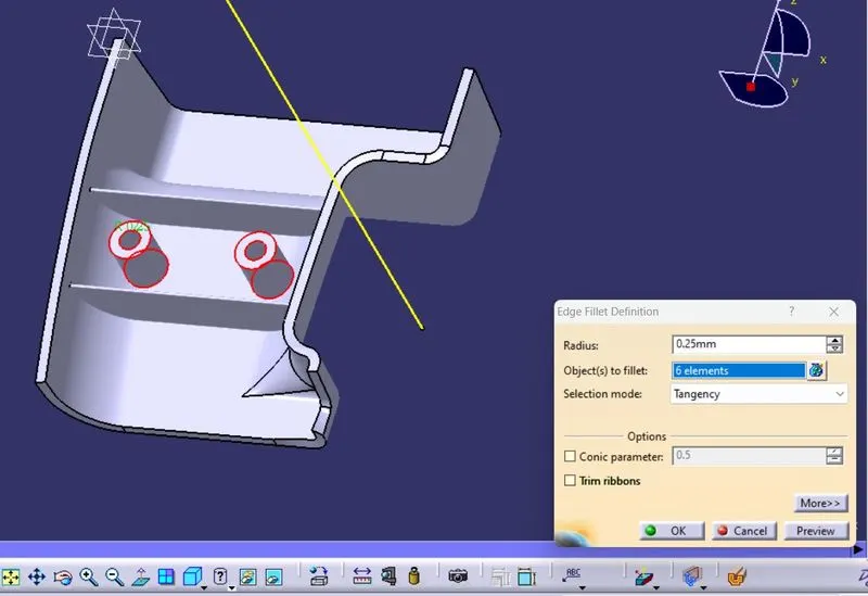
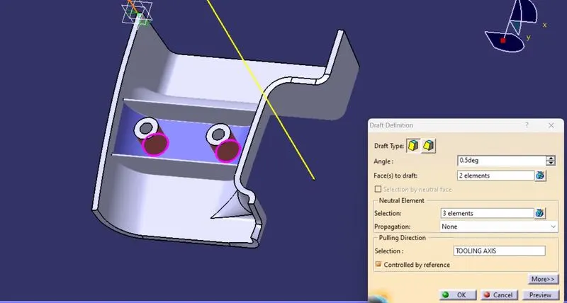
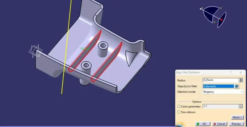
Ribs design-The ribs are designed as per the design clacuaktions.create a line and then extrude it to desired length,it is then given thicknessof 1 mm and then trimmed with the part body.siilarly we can create another rib.Then we can give drfat angle of 0.5 deg on all sides adn then finally giving fillet radius of 0.25 mm.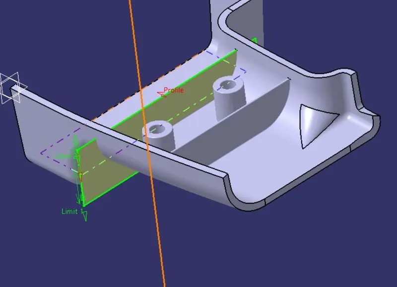
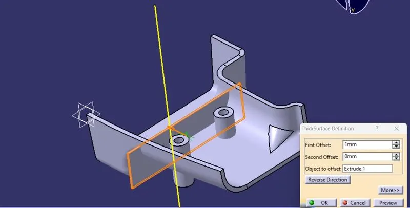
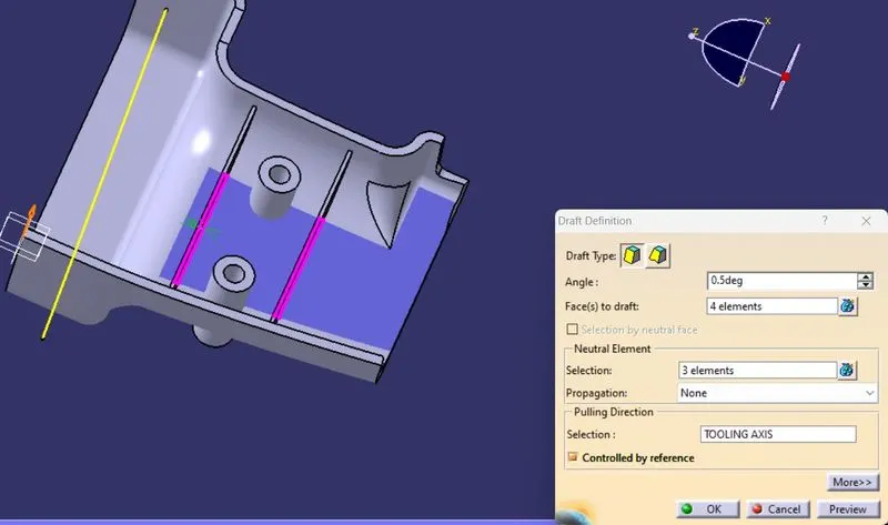
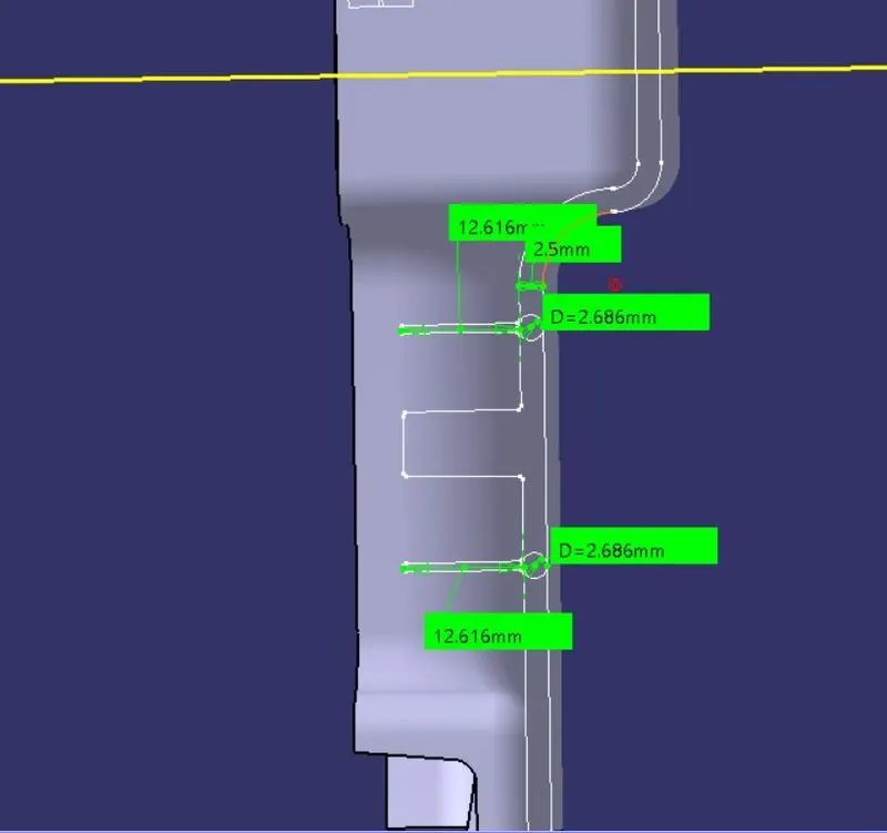
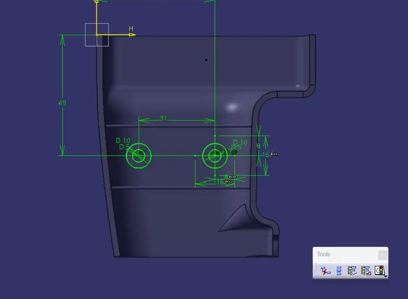
Screw boss-now we need to create the scre boss with by iven dimesnions and then pad it and then trimmed with the part body.the outer body of the screw boss is given a draft angle w.r.t tooling axis upside of 0.5 deg and the inner side is given downside of 0.5 deg.and then giving fillet to the outer and inner parts of the scarew body