Project 1 - 2D meshing on the instrumental Panel
Aim: For the given component, check for the geometrical errors and mesh with the given element Quality criteria. After meshing the component the thickness has to be assigned.
Procedure: Methodology is the same as a basic model to do geometrical cleanup,topological cleanup followed by midsurfacing and following that meshing of the model with given quality criteria and then cleaning the mesh flow, but this is done on a bigger scale in this model and various methodology are combined to obtain the result in record time.
1. Import the model in the ANSA interface
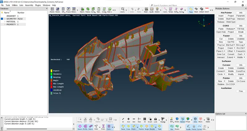
2. Give TOPO command to define the geometry
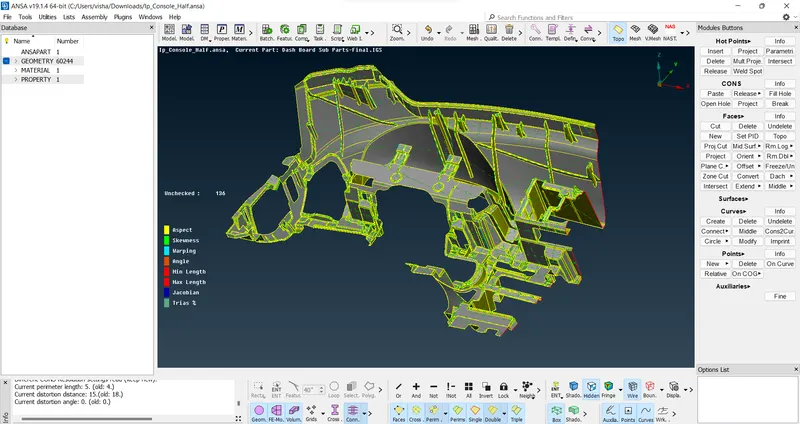
3. Check the geometry
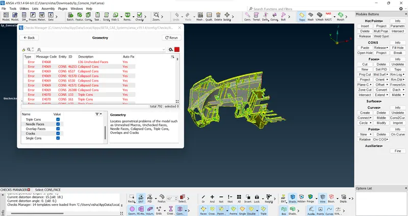
4. Clear the geometry errors using autofix and manual fix options wherever necessary and fill open surfaces as this is a section of a full model.
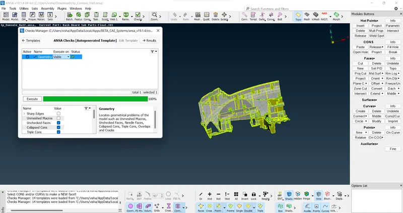
5. Orient the model using visible mode
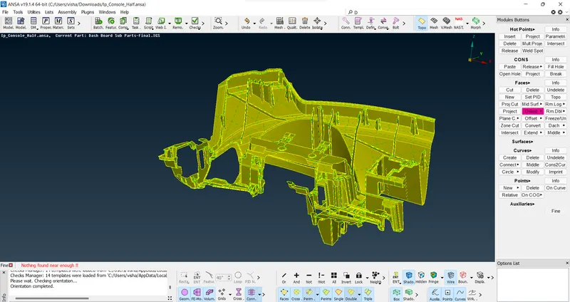
6. Take measurements of the thickness of the model for midsurface extraction
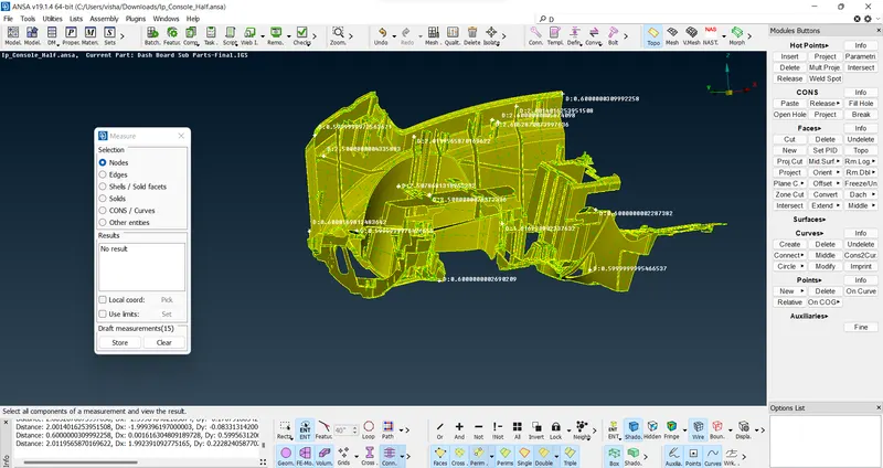
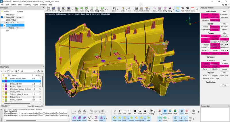
7. Set PID for the features according to their thickness so that they all can be distinguished
Extract midsurface using manual midsurfacing options highlighted in the image as this is a complex feature model and will not yield a feasibe output and might crash due to its size.
A good number of methods are used for different features showcasing diversity of options that can be used on a single model.
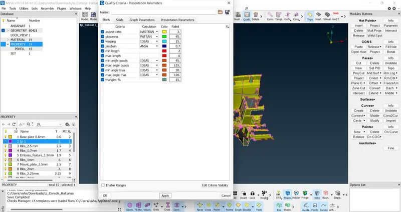
8. Input quality parameters and mesh criteria
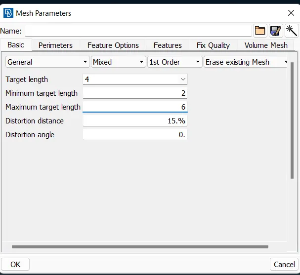
9. Use length option to assign perimters and macros length as 4 to the model and define a mesh surface for the process.
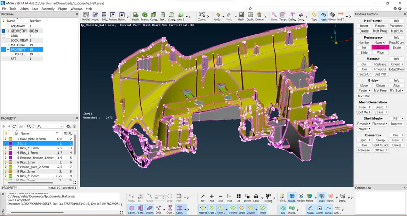
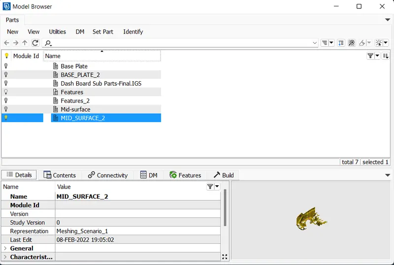
10. Defeature unnecessary or optional cons that can be removed without sacrificing the model features using various methods such as using midcurve option, or moving the cons, making a simple geometrical cons arrangement, deleting unnecessary hot points etc and then input the midsurface into the model browser.
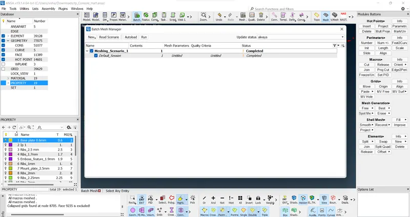
11. Create a batch mesh scenario and run the mesh which will have failed elements and an medium level mesh flow which can be reworked using manual meshing options which will be used in abundanace to perfect the mesh flow.
12. The obtained mesh flow is then worked on by the manual options until a satisfactory mesh flow is achieved, the mesh pattern has some minor failing elements due to the geometry constraint of triple con features and can not be removed and thus can be ignored.
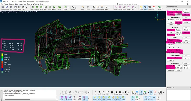
13. The desired model is generated with the highlighted specifications.
Result: A meshed midsurface of a complex model is generated with minor failing elements that can be ignored and thus said model can be used for analysis.
Learning outcomes:
1. Overall knowledge of the modules and how to use them on a large model
2. How to combine multiple methods on the same model
3. Overall idea of expected work of analysis engineer
Drive link of the model: Drive link