Week -2
Aim 1: Make a Simulink model of Doorbell using solenoid block with the following details:
In the above arrangement, when the switch is closed the electromagnet receives electrical power from the battery and pulls the metal arm to hit the bell producing sound.
Create a situation where the switch is closed for 2 seconds and then released. Observe the physical movement of the plunger.
Assume remaining parameters.
Theory: The diagram of the circuit is as shown
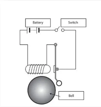
A doorbell works by using a solenoid recieving electrical energy that generates an magnetic field around it causing the hammer to move and hit the bell gong to produce a sound and as long as the solenoid is recieving electric current, the bell will keep ringing.
Simulation block chart:
Logic:
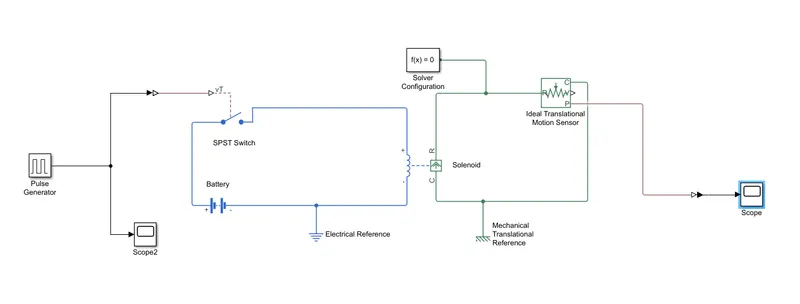
1. The pulse generator is used for generating wave pulses that will be fed as input to the system with the following configuration
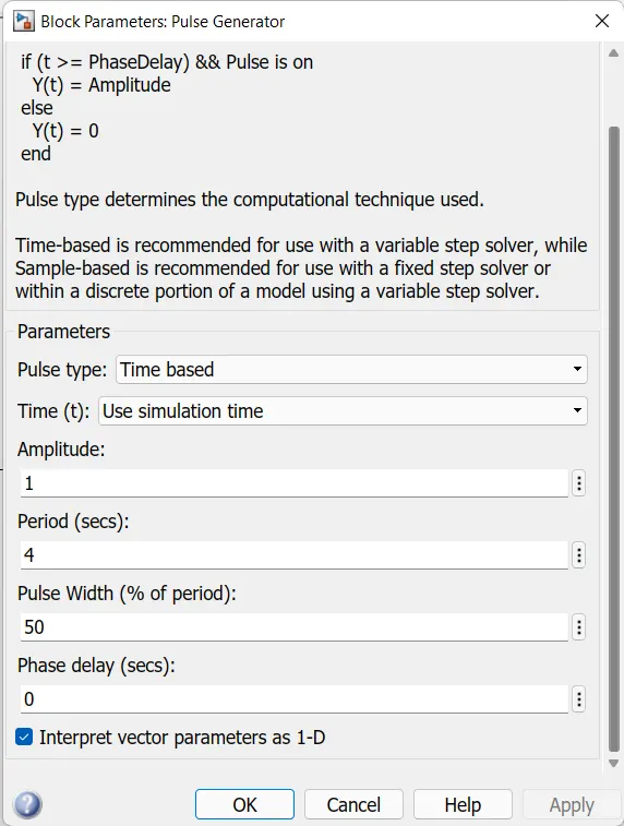
this configuration is selected to simulate the situation where the switch is closed for 2 seconds and then released.
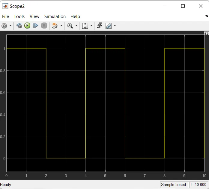
2. A scope is connected to monitor the output of the pulses
3. The output is fed to the SPST switch that completes a solenoid electrical circuit with a battery block, electrical reference and the solenoid.
4. The solenoid is configured with a mechanical parameter to dampen the movement of the hammer so that no large movements can disturb the results.
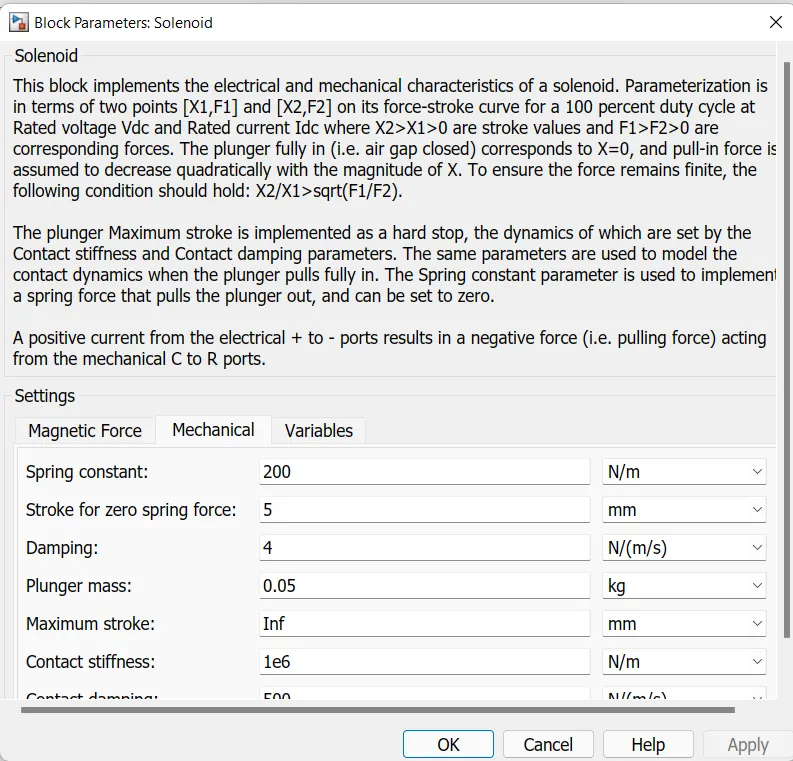
5. The solenoid's mechanical side forms a closed circuit consisting of ideal translational motion sensor, solver configuration and mechanical reference block.
6. The sensor is connected with a scope to monitor the position of the hammer
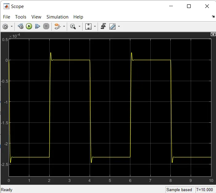
Results:
1. The doorbell circuit is simualted with visible movement of the plunger every 2 seconds
Conclusion:
The simulation is completed with the position of the plunger as expected.
Aim 2: Use a thermistor to sense the temperature of a heater & turn on or turn off the fan as per the below conditions:
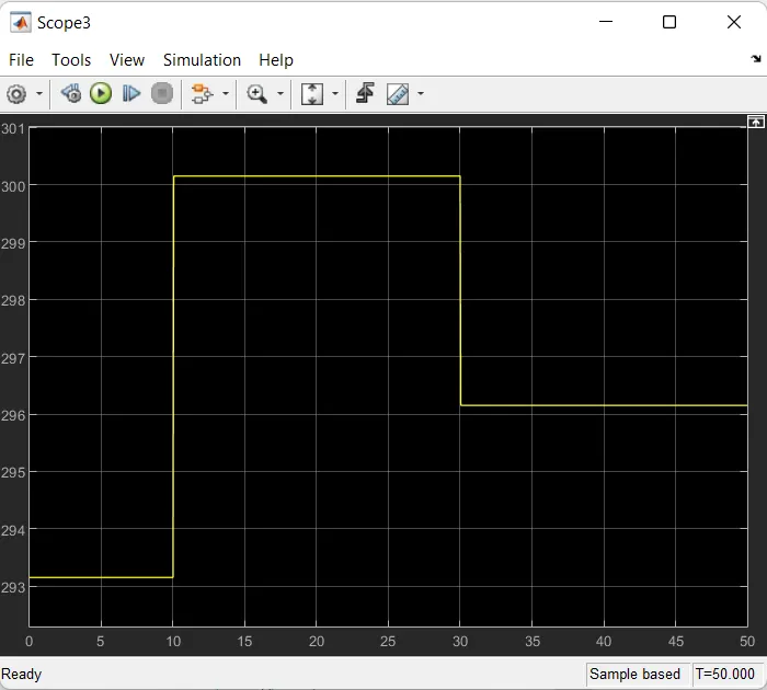
Temperature source: 20 °C from 0 to 10 seconds, 27 °C from 10 to 30 seconds, 23 °C from 30 to 50 seconds
Fan conditions: ON if the temperature above 25 °C, OFF otherwise
Theory: The voltage increases with the increase in temperature and the change in voltage can be used as a trigger for a signal such that the fan turns on when the temperature reaches above 25 deg C, this can be achieved by measuring the threshold voltage of 25 deg C temperature and then the value can be fed to a normal switch with the configuration to only send an output if the input voltage signal crosses the 25 deg C threshold. The output can be fed to a DC motor and the motion can be sensed via a sensor and suitable results can be studied.
Simulation block chart:
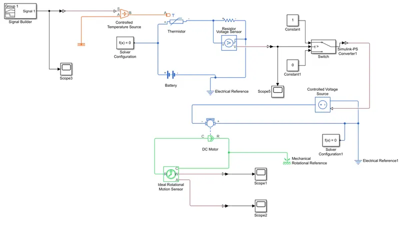
Logic:
1. A signal builder is inserted to input variable time dependent pulses to be fed to the system in the for of temperature values.
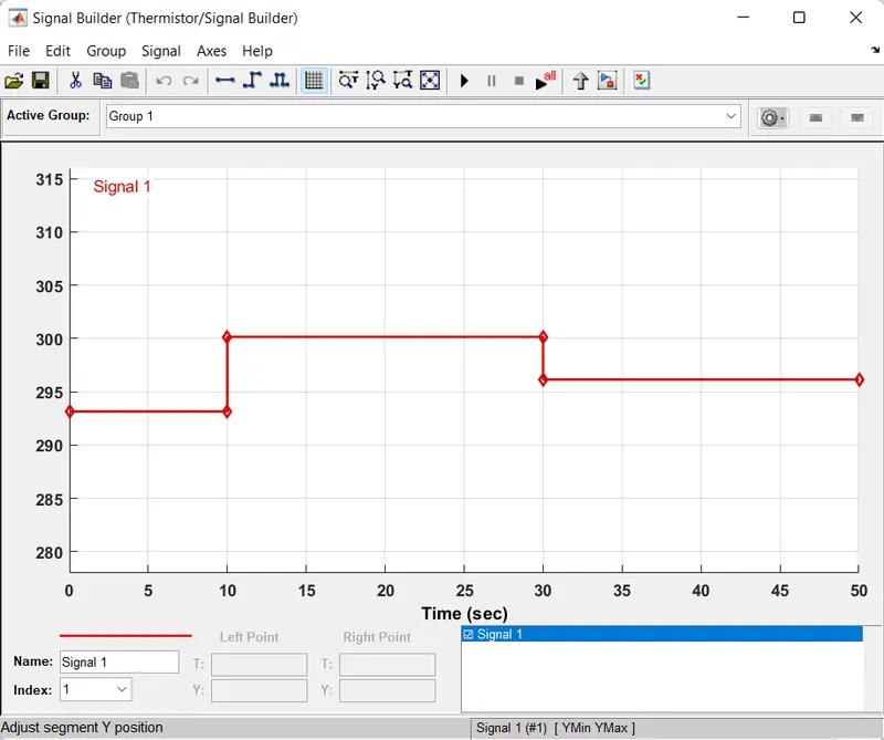
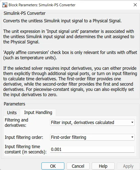
2. The signal is then converted into a simulink signal using simulink PS converter using the following configuration to filter inputs with derivatives calculated as we have time dependent multiple inputs
3. The output signal is connected to a scope to monitor
4. The converted signal is fed to a thermistor block that forms a closed electrical circuit with voltage sensor and resistor to sense the change in voltage with varyinf temperature, a battery and electrical reference.
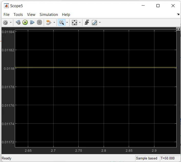
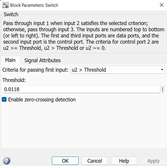
5. The output of the voltage sensor is connected to a switch with the condition to only send the signal if the threshold value crosses the 25 deg C voltage threshold that is 0.0118 and was measured by inputting a 25 deg C constant feed.
7. The output signal is fed to a controlled voltage source that forms a closed electric circuit with the DC motor and solver configuration and an electrical reference.
8. The DC motor forms a closed mechanical circuit with an Ideal rotational motion sensor and a mechanical reference.
9. The output of the sensor are monitored with scopes
Results:
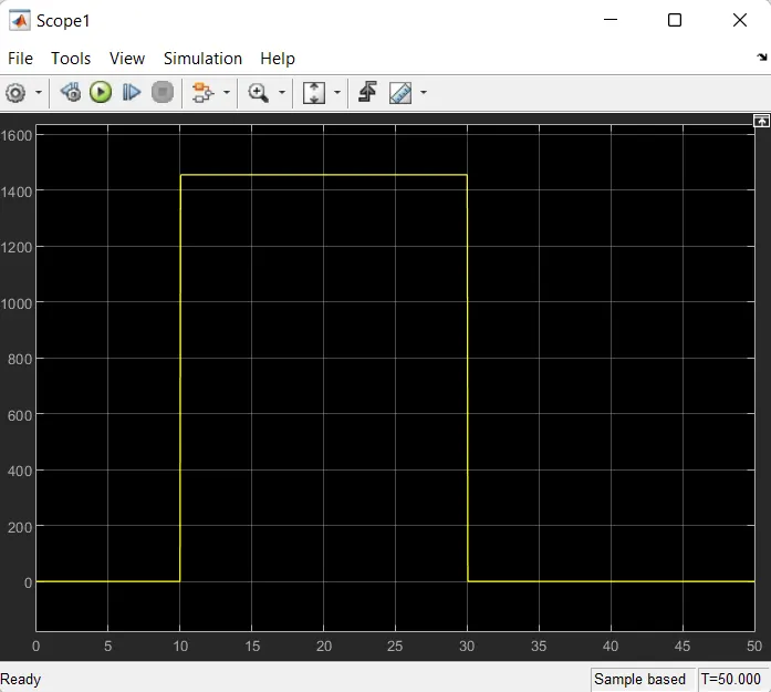
1. The fan turns on for time period 10 sec to 30 sec as temperature reaches above 25 deg C
Conclusion:
The simulation works and yields results as expected
Drive link: Link