Week - 4
Aim:
- Implement control logic of a “washing machine” using Stateflow as per given sequence:
- If the power supply is available, the system gets activated
- If the Water supply is not available, stop the process & indicate through LED
- Soaking time should be 200s followed by Washing time of 100s.
- Then rinsing happens for next 20s & dryer runs for 50s
After all the processes have completed turn on the finished LED
Theory:
1. The washing machine can be built with connecting a stateflow of the machine logic with two inputs(Water supply and power) and can have multiple outputs that can be connected to lamps to indicate the process.
2. The logic can be assembled as given in the question by giving the input water supply two outputs on the condition provided namely water supply off and on, if the waters supply is off, the circuit does not advance and the processes do not advance while if power and water supply are on, the whole process finishes and the lamps light up.
Procedure:
1. Import the stateflow chart in the panel where we can write the logic of the washing machine
2. Import two constant value switch which can be connected with a constant bloack to the stateflow as input namely, Power input and water supply
3. Create the stateflow logic with the condition that if water supply is giving 0 value, there is no water supply indication and the washing does not progress
4. And if the warter supply is 1, then the whole process including, soaking, washing, rinsing and drying happen with their time period and give outputs for their respective time and a finished state output.
5. Connect the outputs to display block and then connect those display blocks to lamps which give green light if the process is finished and the output is 1 otherwise they give red light with 0 output.
6. Carry out processes with different inputs to check the working of machine.
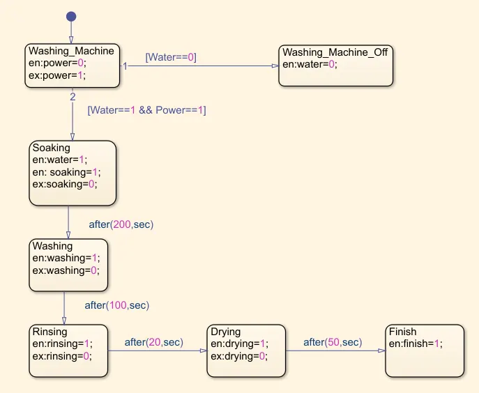
Stateflow logic:
1. Washing machine recieves the inputs and has two different output in accordance to the water input,
2. If water supply is off, the logic is to shut down the machine
3. If water supply is on, the logic follows to th end as defiend.
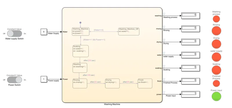
The power input is on but the water supply is off
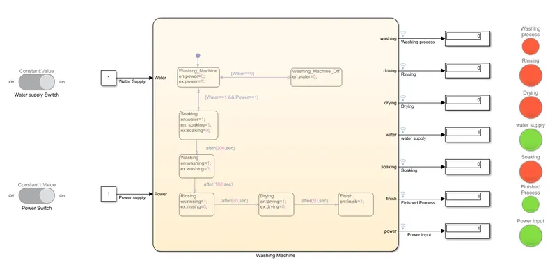
The power and water input are on and thus the process completes
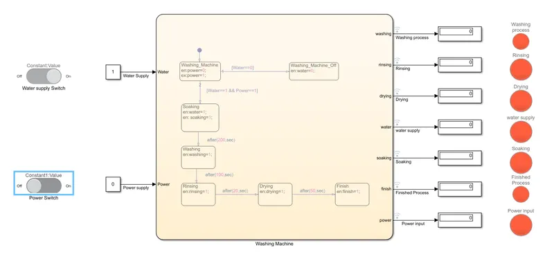
The power input is OFF and thus no process is carried out
Conclusion: achieved the simulation of washing machine with multiple input conditions and output gauging
Aim:
2. Make a Simulink chart for the “Gear shift” logic as per below conditions:
Speed Range(kmph) Gear
0 to 15 1
16 to 25 2
26 to 40 3
41 to 60 4
Above 61 5
Give speed input while the simulation is running & display the gear number.
Theory:
1. We can make a stateflow logic where the respective speed gives out the respective gear number and that output can define the lamp output
Procedure:
1. Import the stateflow chart and write the logic defining the gear speed with gear number and make a reversible logic
2. Connect the a constant block with a slider gain and connect that as an input speed to the stateflow
3. connect the output to a display block
4. The output gear can be connected to a lamp that has a definite color for every gear and displays the different gear with color change
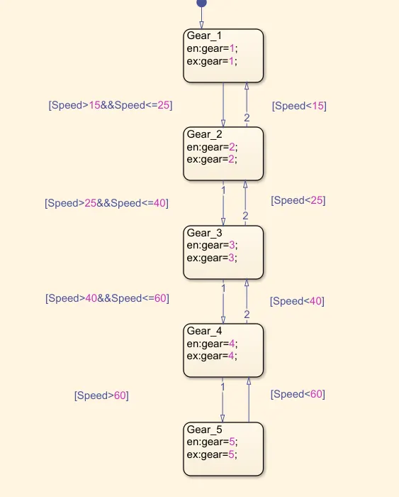
Stateflow logic:
1. The input speed has been given multiple conditions according to the gear and speed conditions and a definite output for every gear
2. The logic is reversible in case speed lowers
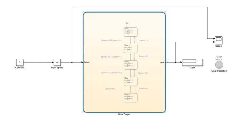
Simulation
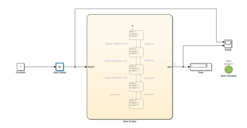
The simulation is ran inifinetly until stopped
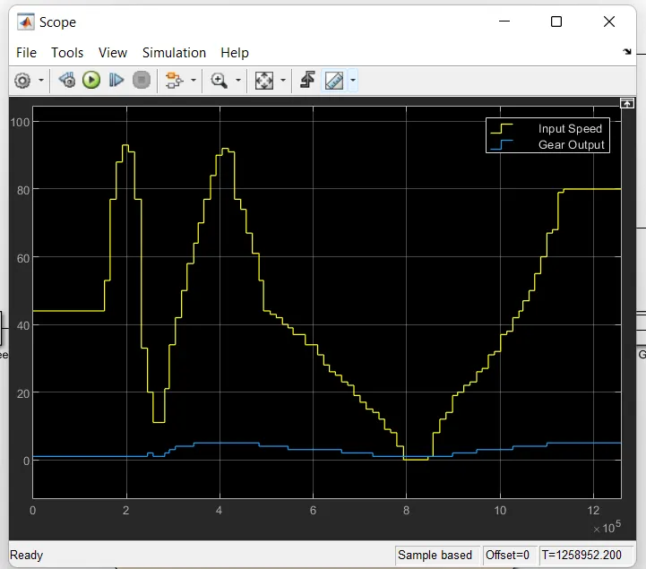
This is the scope view of the speed and gear with the time the simulation ran
Conclusion:
Achieved gear simulation with multiple speed inputs and variable speeds.
PS: files have been attached for review