Week 3 - 2D meshing for sheet metal
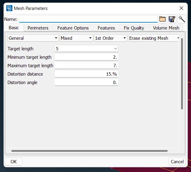
Aim: For the given Hood model, Take the mid surface for all the components after checking the geometrical errors and mesh the mid surface with the given element Quality criteria. (Refer the table Below for the Quality criteria)
|
S.No |
Quality Criteria |
Value |
|
1 |
Target/Average length |
5 |
|
2 |
Minimum Length |
2 |
|
3 |
Maximum Length |
7 |
|
4 |
Aspect |
3 |
|
5 |
Warpage |
15 |
|
6 |
Skewness |
45 |
|
7 |
Jacobian |
0.7 |
|
8 |
Minimum Quad Angle |
45 |
|
9 |
Maximum Quad Angle |
135 |
|
10 |
Minimum Tria Angle |
30 |
|
11 |
Maximum Tria Angle |
120 |
|
10 |
Tria Percentage |
15 |
Theory:
Before initiating an actual task it is important to prepare for the task in order to achieve the desired result. This is true in the simulation world too. Every CAE simulation requires some preparation to be done before it can be numerically set up and performed. This step is called Pre-processing. In this step, you will amongst other things upload and clean the CAD geometry, create the simulation domain, and generate the mesh. For the uploaded CAD geometry to be valid it is necessary to be checked for any errors, for eg. intersecting faces or open edges. This is done by cleaning the geometry and making it mesh friendly. A mesh is a discretization of the domain to be simulated into tiny cells or segments. This discretization will most likely fail if the geometry is invalid. For Finite Element Analysis, you will usually create a mesh of the actual model.
For a correct and efficient setup of your simulation, you should make sure that your CAD model has the right topology for the simulation to run. In general, a CAD model consists of different types of topological entities such as solids, faces, edges, or vertices. You should be aware of this topology since it will have an impact on how the mesh is generated.
A mid surface is generated for the solid modelas when we do mid surface meshing (in 2D shell meshing), there is no need for a detailed volume mesh as the thickness of the geometry is not needed for a detailed volume mesh.
The element thickness is assigned as half in one direction and half in other direction. Mathematically, half in the + Z direction (element top) and the other half in the – Z (elements bottom).
A mesh is a network that is formed of cells and points. It can have almost any shape in any size and is used to solve Partial Differential Equations. Each cell of the mesh represents an individual solution of the equation which, when combined for the whole network, results in a solution for the entire mesh.
Solving the entire object without dividing it into smaller pieces can be impossible because of the complexity that is within the object. Holes, corners and angles can make it extremely difficult for solvers to obtain a solution. Small cells, on the other hand, are comparably easy to solve and therefore the preferred strategy.
It’s common to classify mesh types as structured or unstructured.
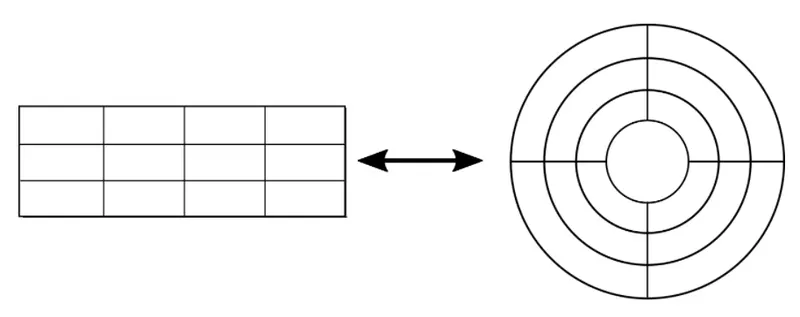
Structured meshes, also commonly called grids, are meshes whose structure and formation allow for easy identification of neighboring cells and points, This property is derived from the fact that structured meshes are applied over analytical coordinate systems (rectangular, elliptical, spherical, etc.), forming a regular grid.
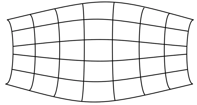
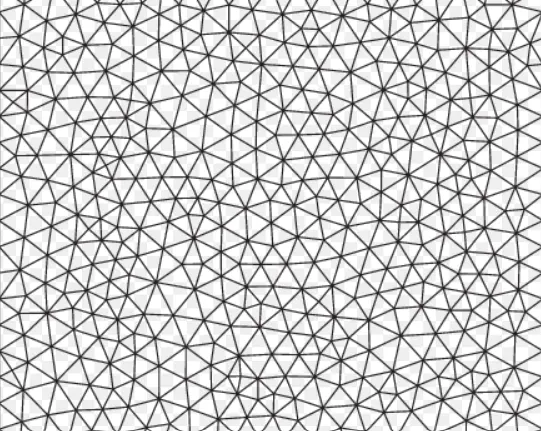
Unstructured meshes are more general and can arbitrarily approximate any geometry shape. In contrast with structured meshes, where the coordinates and connectivities map into the elements of a matrix, unstructured meshes require special data structures, such as an adjacency matrix or list and the node coordinates list. The unstructured mesh node/cell numbering can be arbitrary and sparse since it does not require any analytical form of adjacency query.
Procedure:
1. Input the given hood model in ANSA software
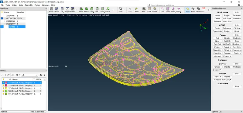
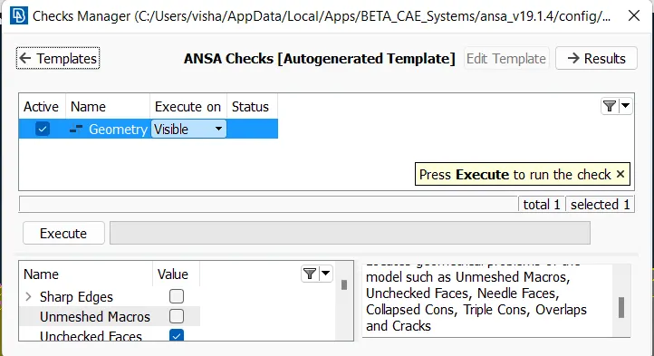
2. Check for geometry errors in the check menu
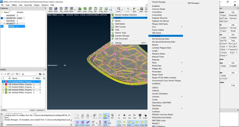
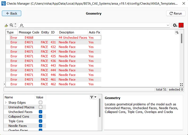
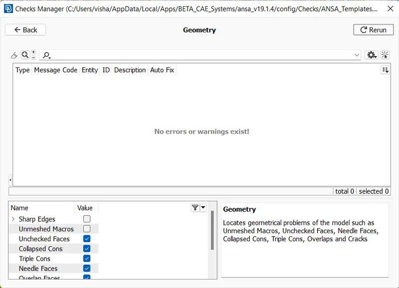
3. Fix the errors from that window
4. Select each part of the assembly individually and check the thickness of the part and then extract the midsurface by using midsurface option from the modules button(Faces)
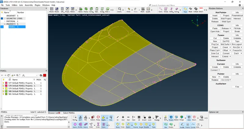
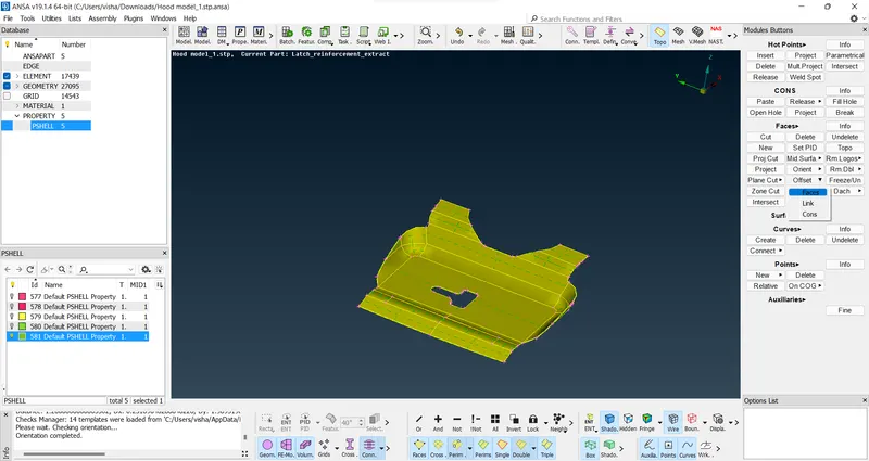
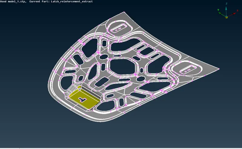
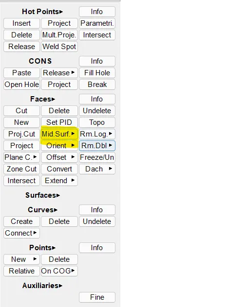
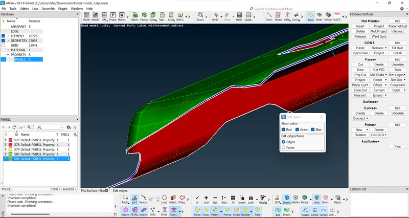
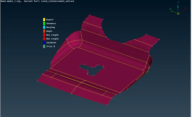
There are two ways to extract the midsurface of a model, manually by ofsetting the individual faces and automatic by using mid surface option, selection is based upon the complexity of the model(If model is complex and midsurface is not properly defined by the automatic method, we use manual approach to achieve precision).
5. Create a new PSHELL material for the midsurface and assign the thickness of the part in the properties tab.
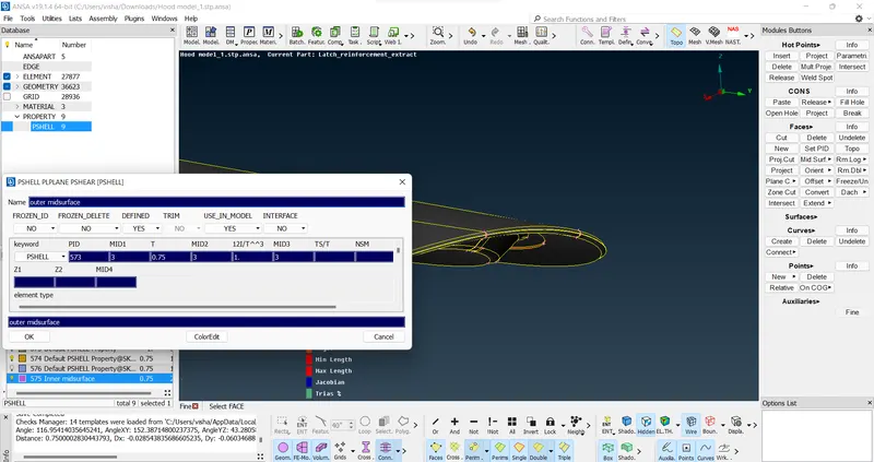
6. Apply the created PSHELL to the created midsurface
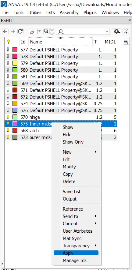
7. Define the mesh parameters and the given quality criteria

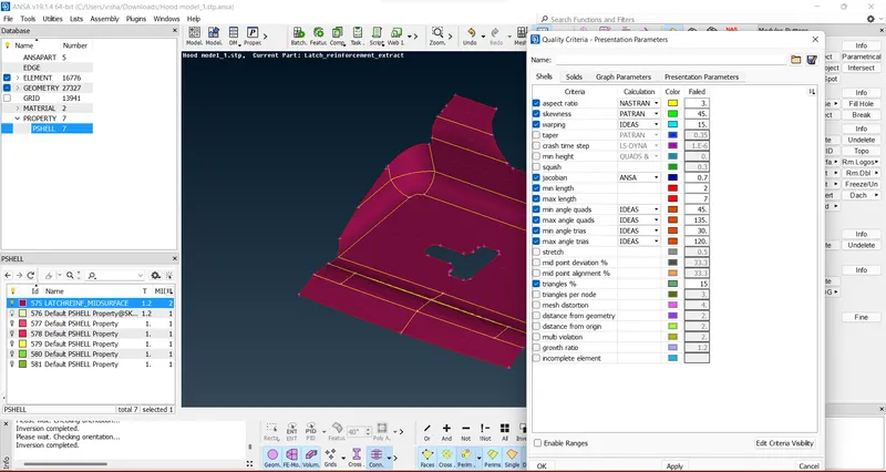
8. Open the mesh module button tab and define the perimeter and macros length as 5 as given
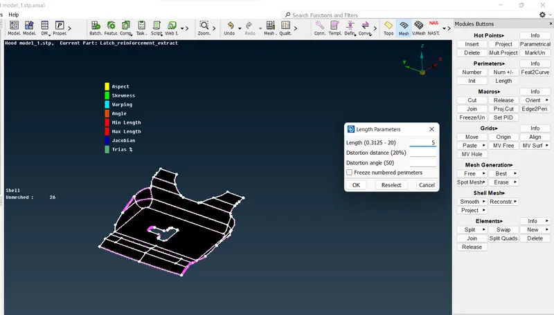
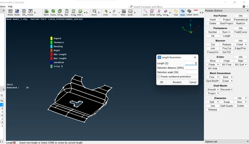
9. Mesh the faces of the models using various meshing options as shown
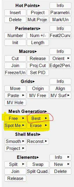
The maximum use is of the best mesh module in this particular model as it provides better results without much experience needed.
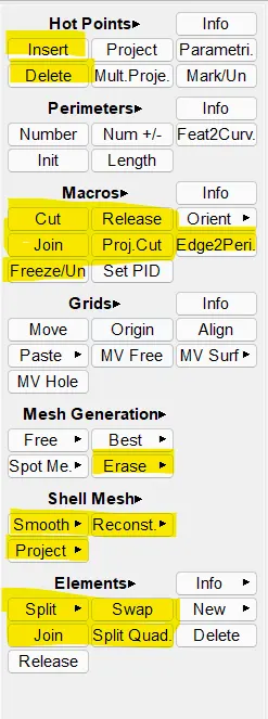
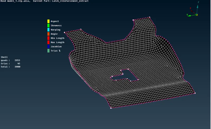
10. Switch to hidden mode of the graphic window and focus on failing quality criteria and fix them with the available tools and try to remove trias as much as possible with no trias touching the corner or holes of the model.
11. Check the geometry with the check option to do a final check of the mesh surface with unmeshed macros option ON
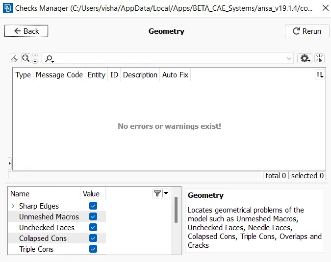
12. Repeat this process for every part and achieve best mesh for the assembly file.
Inner extract-
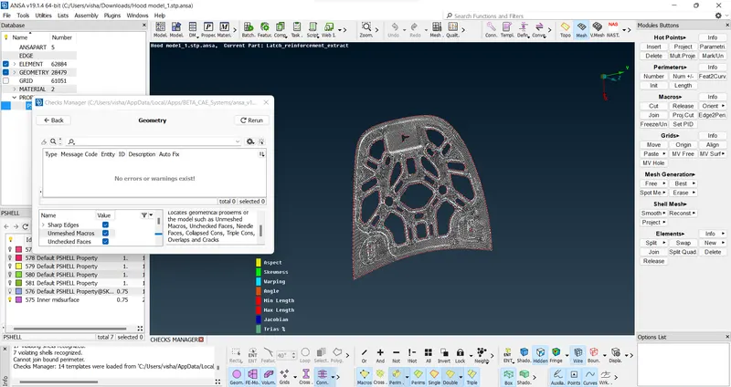
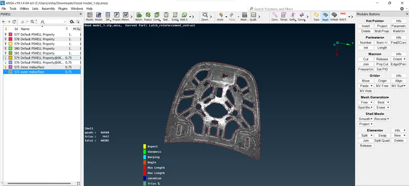
Outer extract-
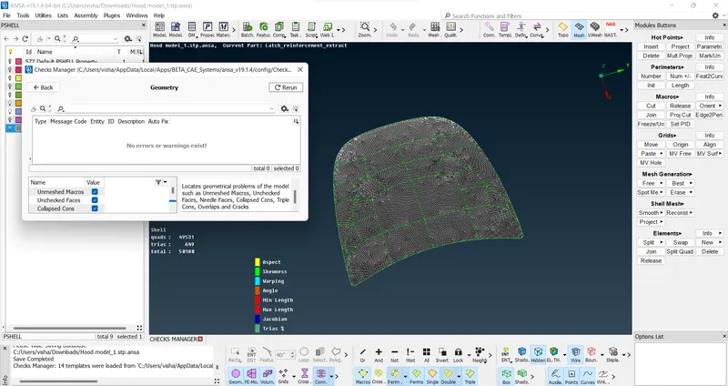
Latch-
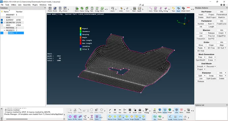
Hinge-
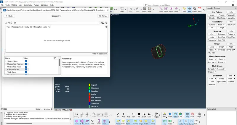
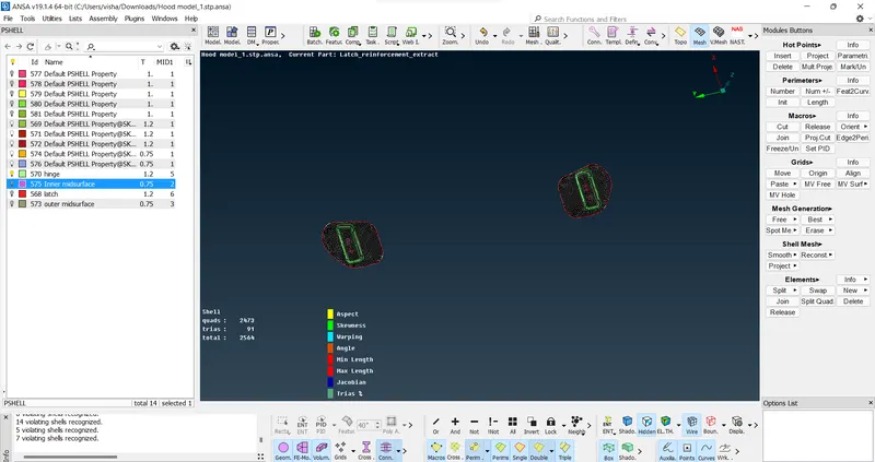
13. The final step is to check the trias percentage in the model i.e, visible in the left corner of the graphic window
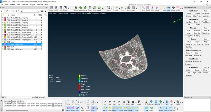
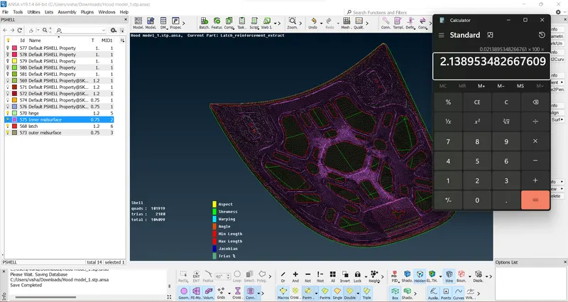
The trias percentage in the model is 2.13% that is well below the allowed limit and thus the mesh can be considered to be under quality restrictions and a good mesh.
Learning outcomes: The outcome is a meshed model with a good mesh pattern and the user has more confidence and exposure to the tools and what needs to be done to solve and rectify different errors in meshing and topology cleanup.
The link to the ansa file: ANSA file of car hood Google drive link.
Reference:www.simscale.com