Project - 2 - Meshing on the suspension Assembly
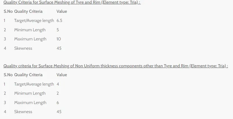
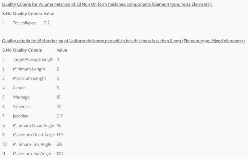
Aim: For the given assembly, check for the geometrical errors and mesh with the given element Quality criteria. After meshing the component the thickness has to be assigned for mid surfaces. Use tetra elements to model non-uniform thickness components. Also use Appropriate connections to connect the components, at last perform Symmetry command to reflect the half finished model to the other side.
Thoery:
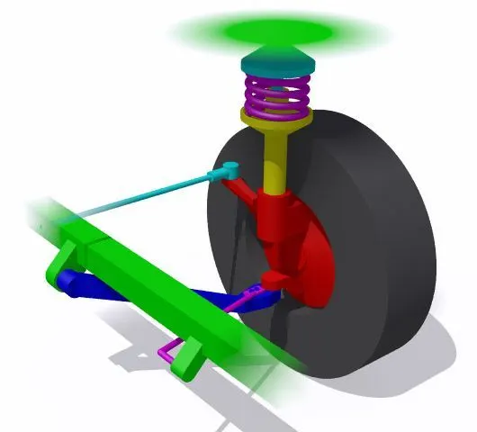
Suspension is the system of tires, tire air, springs, shock absorbers and linkages that connects a vehicle to its wheels and allows relative motion between the two. Suspension systems must support both road holding/handling and ride quality, which are at odds with each other. The tuning of suspensions involves finding the right compromise. It is important for the suspension to keep the road wheel in contact with the road surface as much as possible, because all the road or ground forces acting on the vehicle do so through the contact patches of the tires. The suspension also protects the vehicle itself and any cargo or luggage from damage and wear. The design of front and rear suspension of a car may be different.
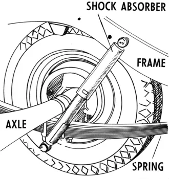
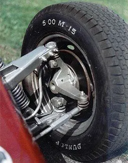
A MacPherson strut uses a wishbone, or a substantial compression link stabilized by a secondary link, which provides a mounting point for the hub carrier or axle of the wheel. The lower arm system provides both lateral and longitudinal location of the wheel. The upper part of the hub carrier is rigidly fixed to the bottom of the outer part of the strut proper. That slides up and down the inner part of it, which extends upwards directly to a mounting in the body shell of the vehicle. The line from the top mount of the strut to the bottom ball joint on the control arm gives the steering axis inclination. The axis of the strut may be angled inwards from the steering axis at the bottom, to clear the tyre, which makes the bottom follow an arc when steering.
To be really successful, the MacPherson strut required the introduction of unitary construction, because it needs a substantial vertical space and a strong top mount, which unibodies can provide, while benefiting them by distributing stresses. The strut will usually carry both the coil spring, on which the body is suspended, and the shock absorber, which is usually in the form of a cartridge mounted within the strut (see coilover). The strut can also have the steering arm built into the lower outer portion. The whole assembly is very simple and can be pre-assembled into a unit. As well, the elimination of the upper control arm allows for more width in the engine compartment, which is useful for smaller cars, particularly with transverse-mounted engines, such as most front wheel drive vehicles have. The assembly can be further simplified, if needed, by substituting an anti-roll bar (torsion bar) for the radius arm. For those reasons, it has become almost ubiquitous with low cost manufacturers. Furthermore, it offers an easy method to set suspension geometry.
Many modern versions replace the lower control arm with a wishbone. An anti-roll bar is optional and, if present, is attached by a ball-jointed rod to the spring-damper, or by a ball or elastomerically jointed rod to the wishbone.
Procedure:
1. Insert the model in the ANSA interface
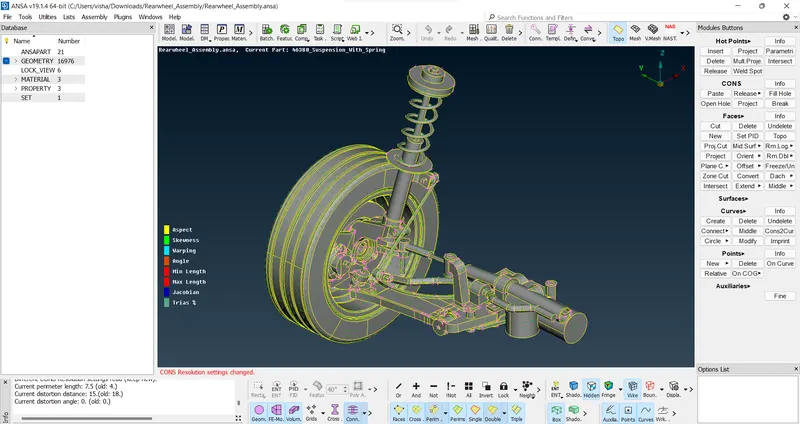
2. Check for geometrical errors and fix them via autofix and manual fix commands wherever necessary
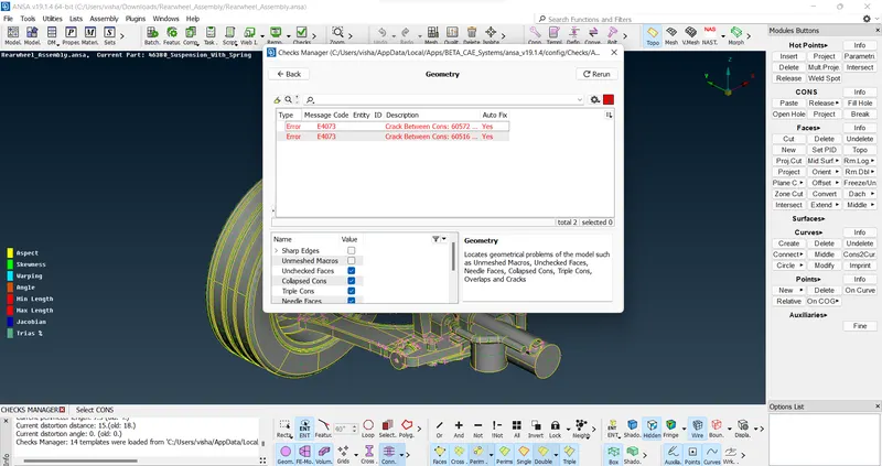
3. Measure the components and identify which part will be suitable for mid-surface extraction and mixed meshing and which ones will be suitable for volumetric meshing.
4. Extract the part suitable for midsurface extraction
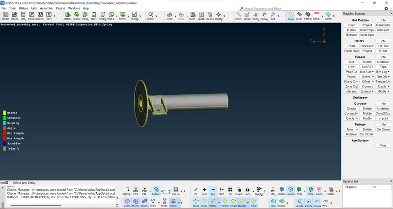
5. Check for geometrical errors once more and extract the midsurface using offset command

6. Mesh the extracted surface by first defining the element length and then inputting the quality criteria and mesh parameters
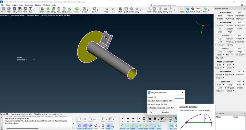
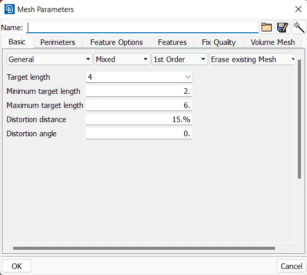
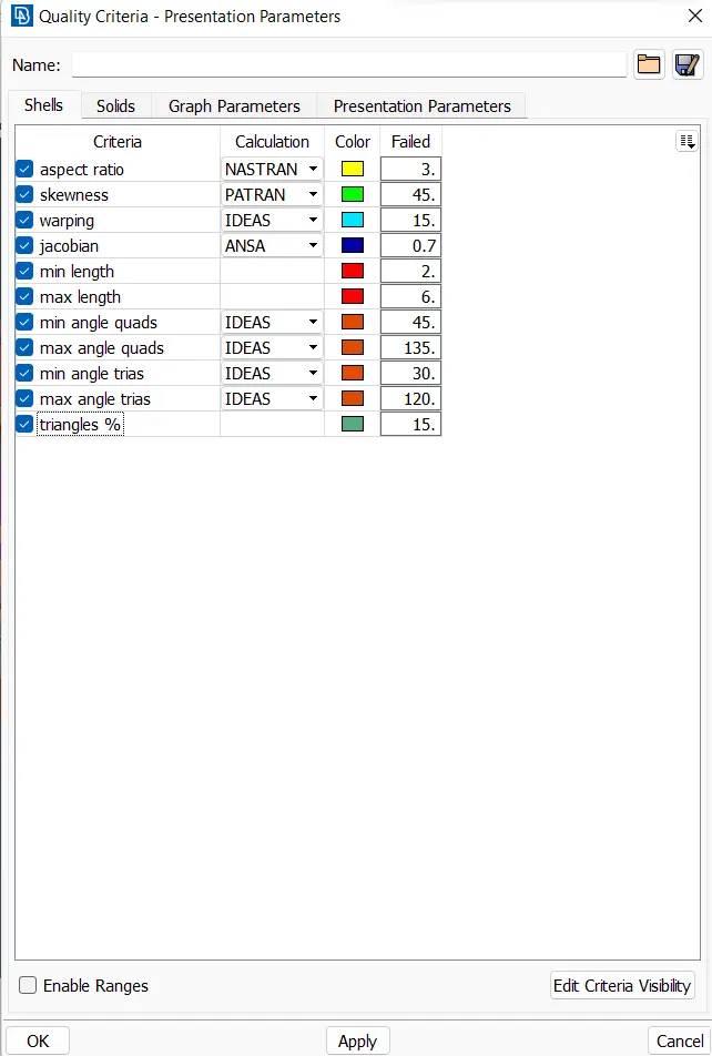
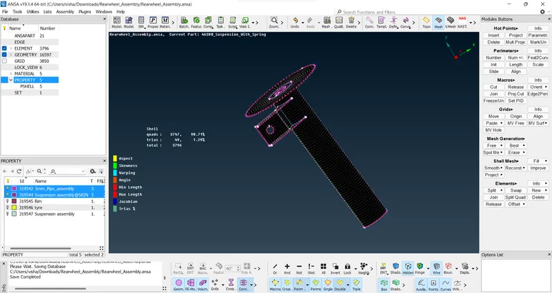
7. After that, extract the wishbone yoke as it is a constant thickness part with thickness less than 5mm, this part needs to be extracted out of the whole PID region and defined as a new PIDand repeat the steps as defined above
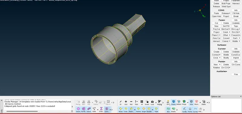
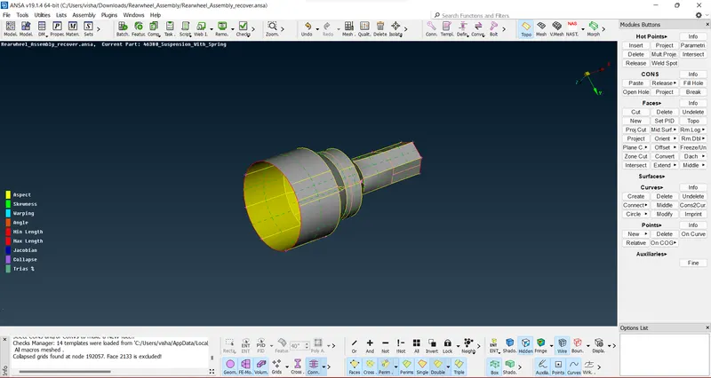
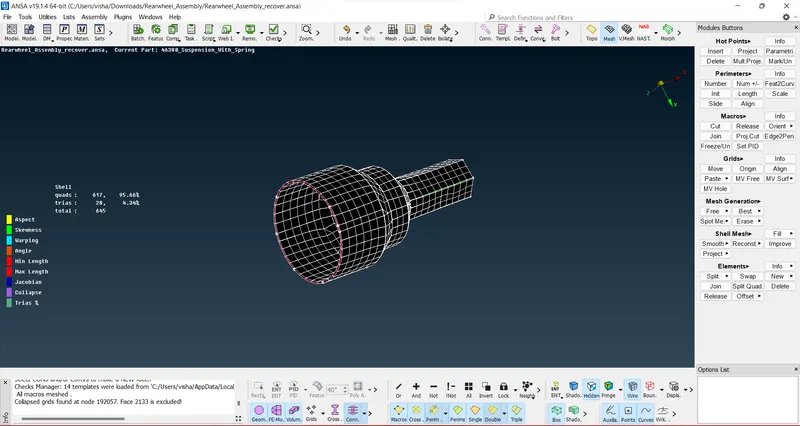
8. Extract the tyre and rim of the assembly and check for geometrical errors
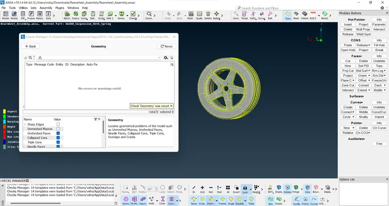
9. Define the numbers at the parts such that they are even numbers and clear topological cons if necessary
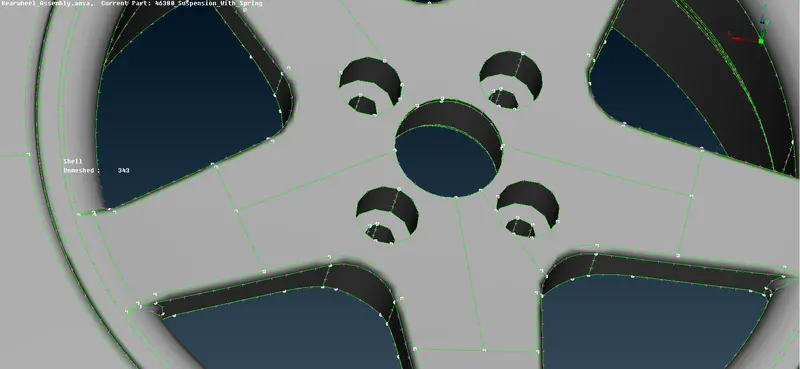
10. As this is a large assembly, batch meshing can be done to save time and necessary manual fix can be applied post batch meshing to save a lot of time.
These models need to defined in the model browser list and then they can be loaoded up in batch meshing module
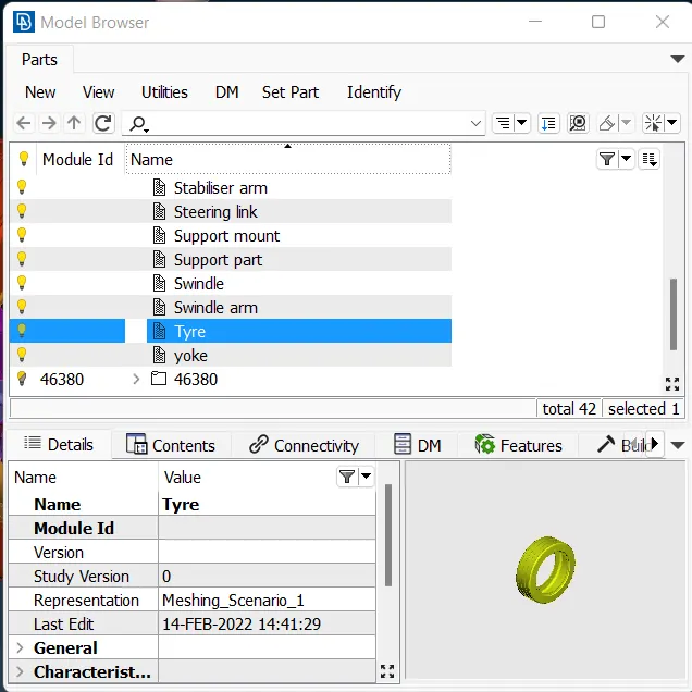
11. Create a meshing scenario and load up the model
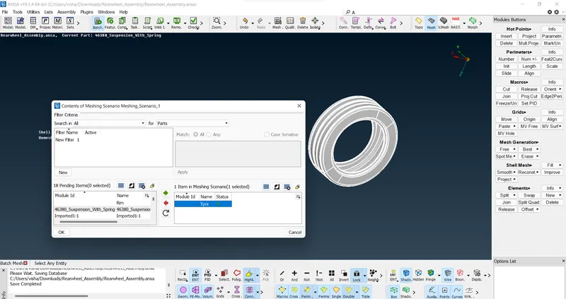
12. Define the quality criteria and mesh parameters
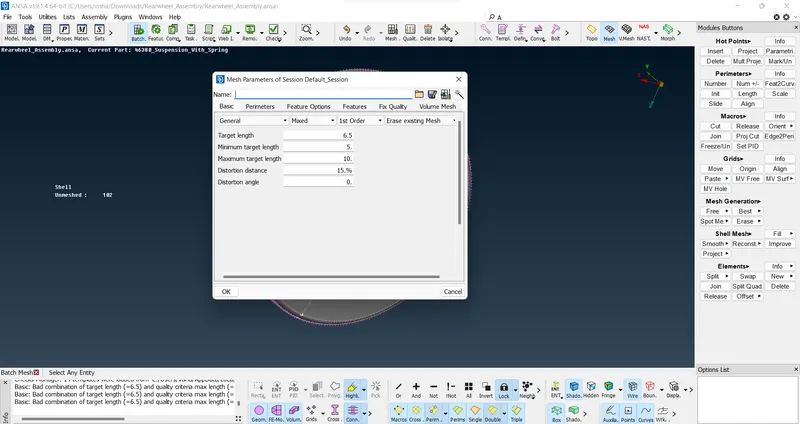
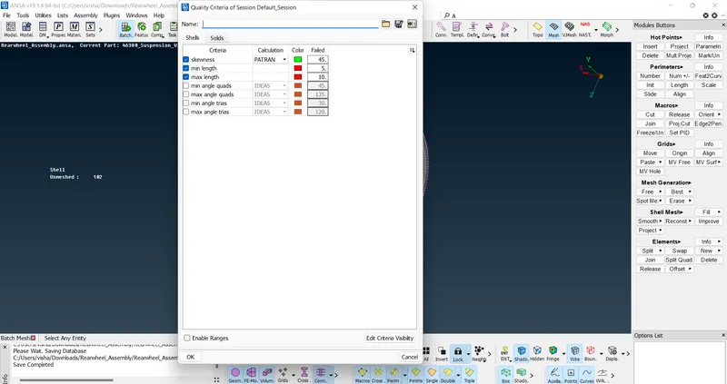
13. Run the scenario
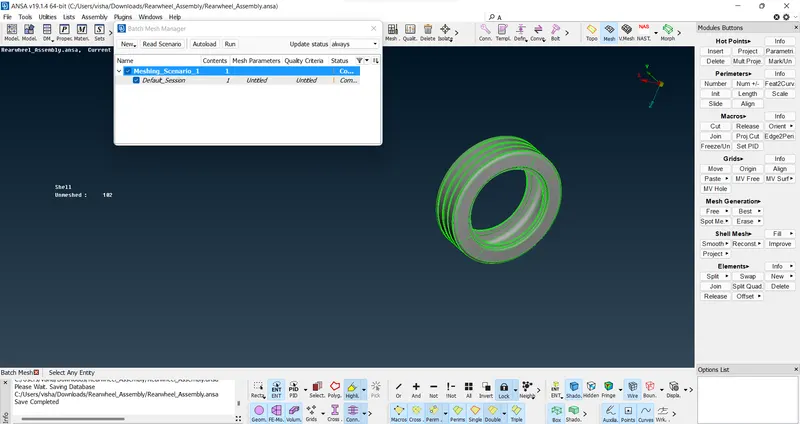
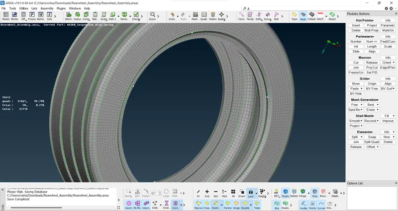
14. Check for failing elements and fix them by using reconstruct command and deploying necessary pattern.
15. After that, switch to volumetric mesh deck and define the volume using manual --> auto option and define the volume by selecting the visible model
16. Following that, mesh the defined volume using either Tetra rapid or tetra FEM,
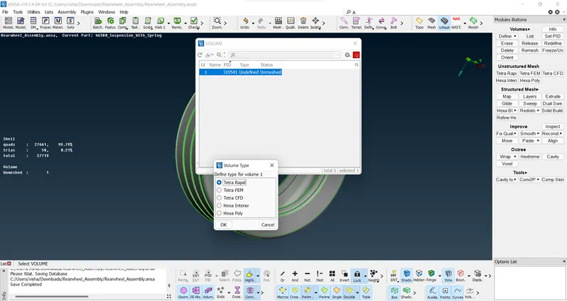
17. Fix any failing criteria if present and then apply PID using SET PID option to the volume MESH
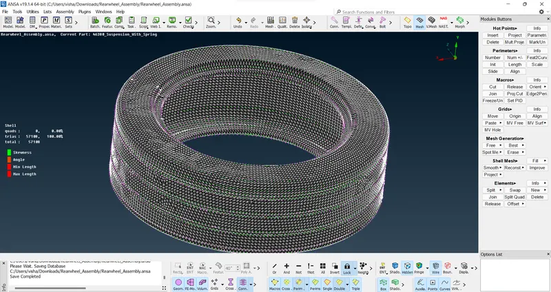
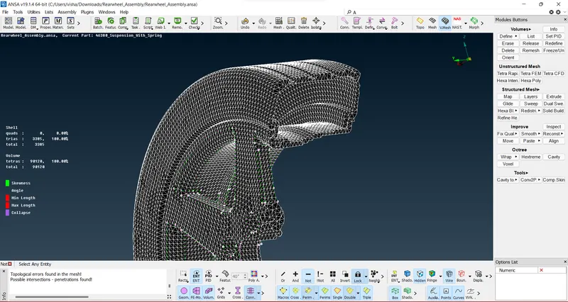
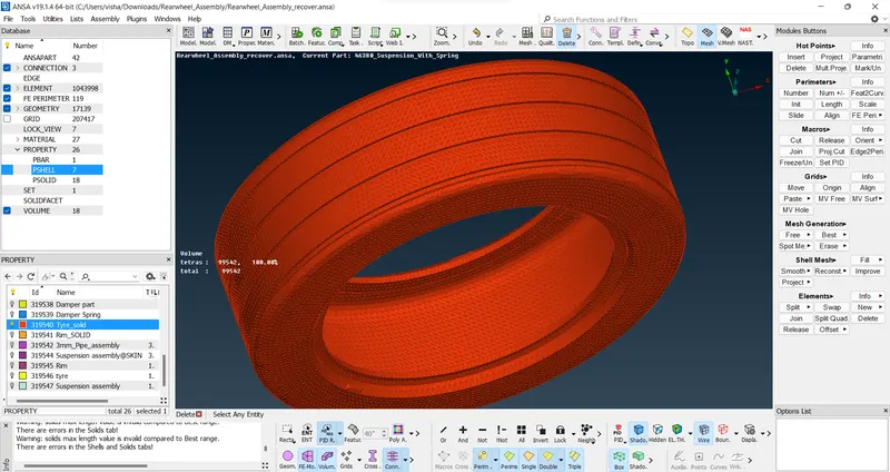
18. Repeat the same steps for the rim
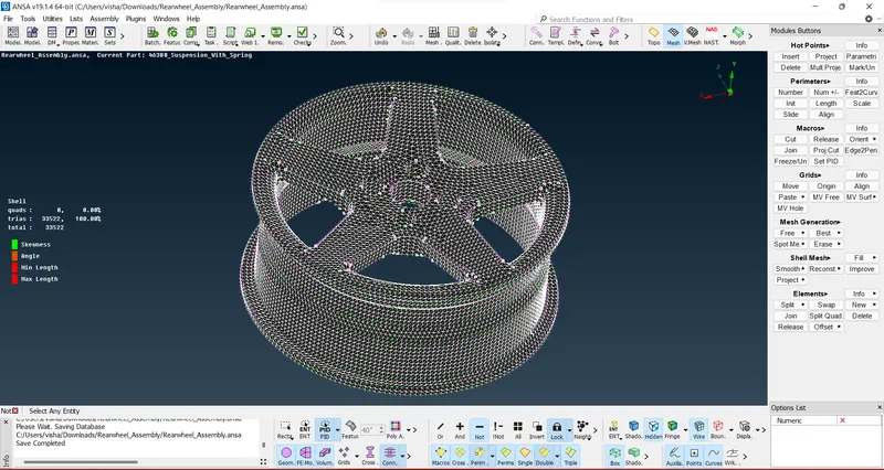
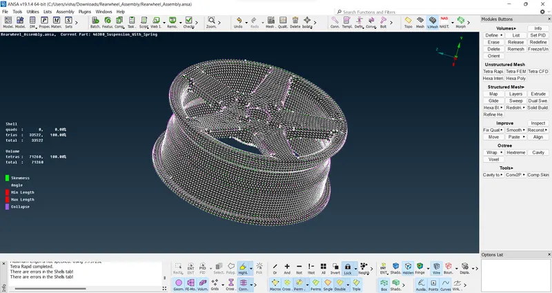
19. Define the meshing parameters and quality criteria for rest of the components and do the same process
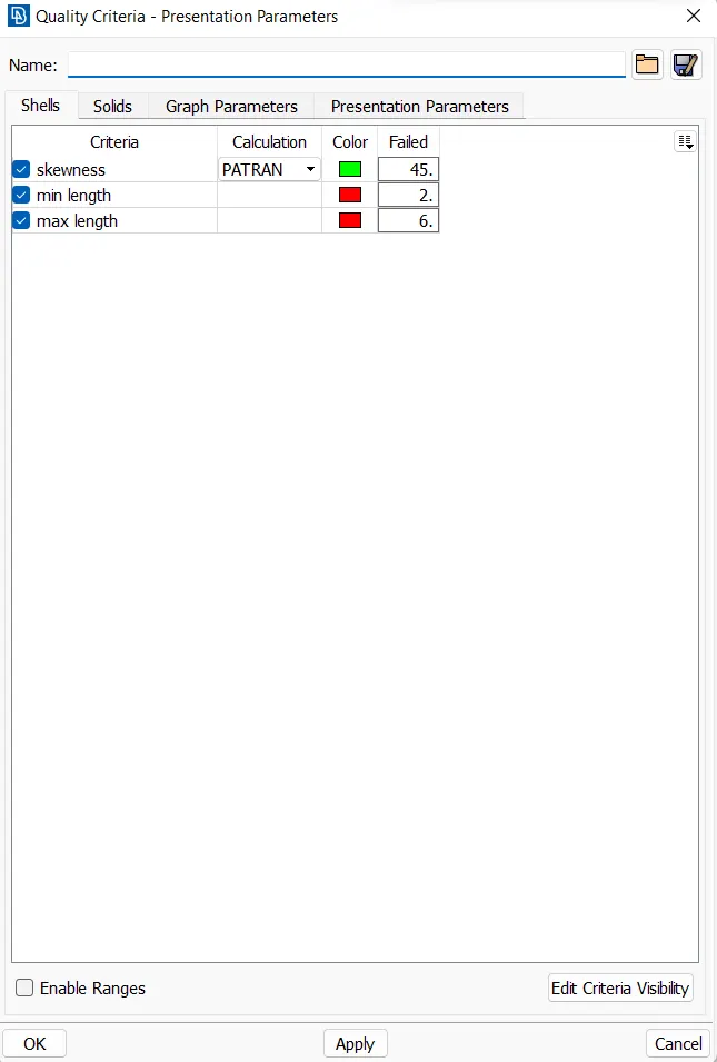
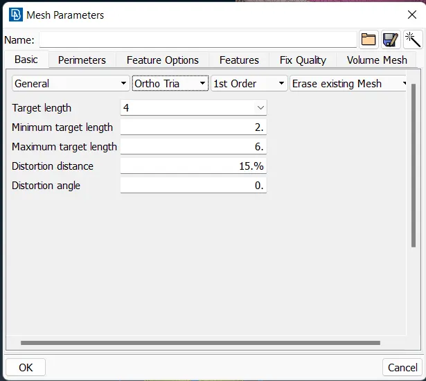
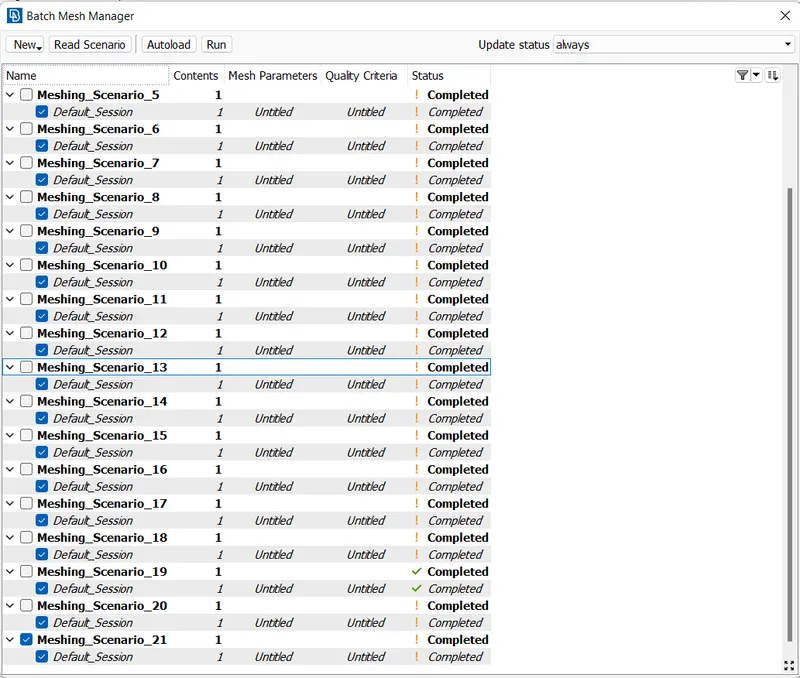
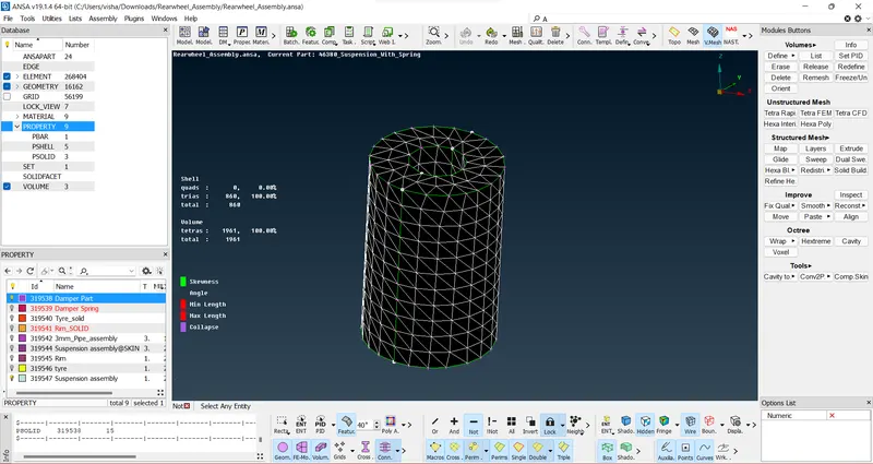
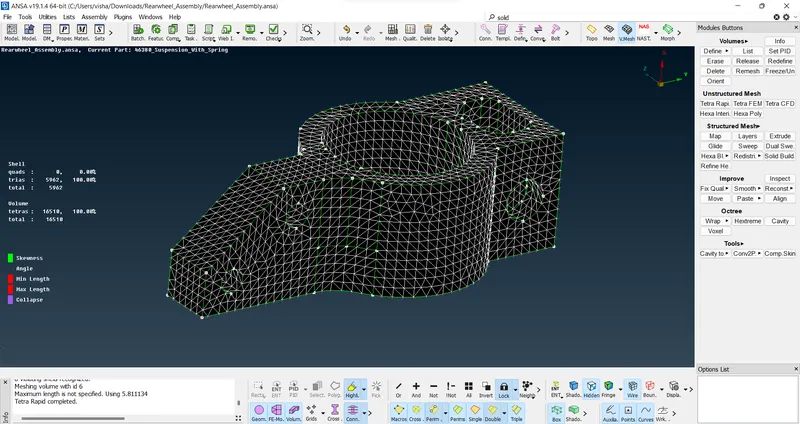
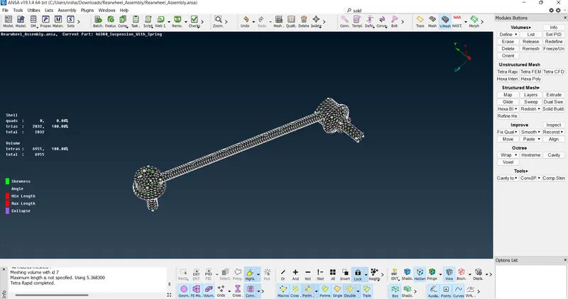
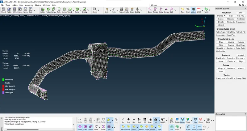
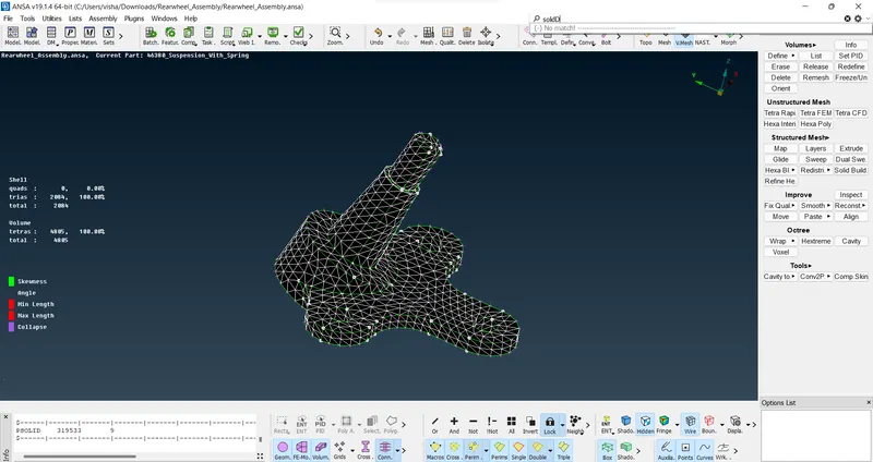
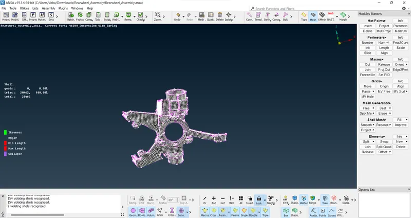
and so on,
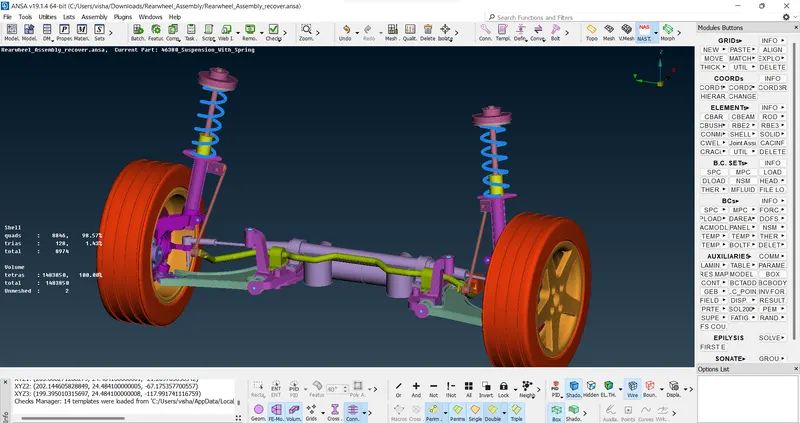
20. The model is obtained
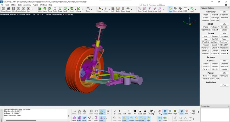
21. We apply the connections to the assembly:
The connections used are RBE2, seam weld connection, and bolt connection
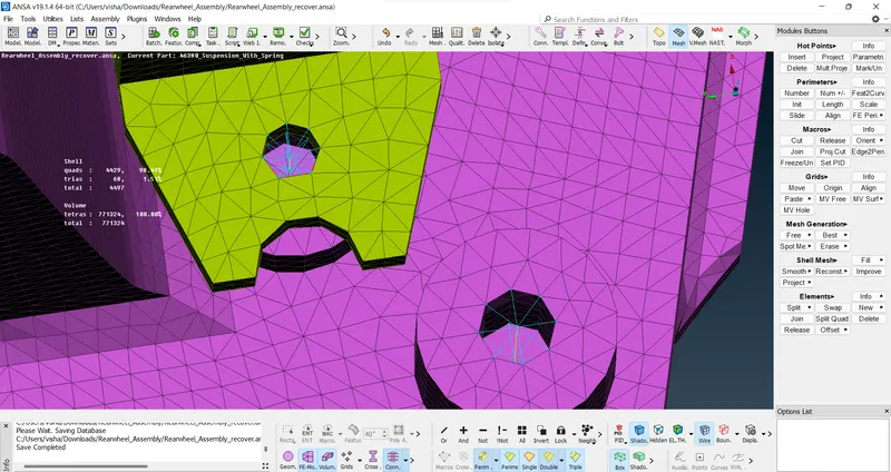
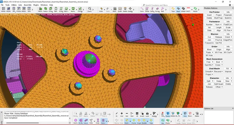
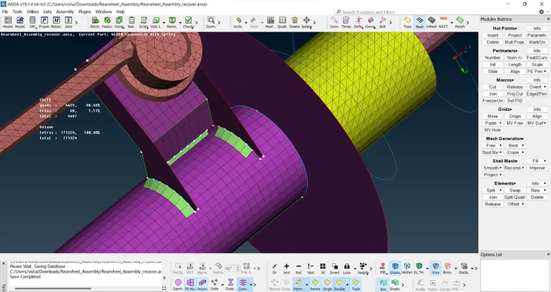
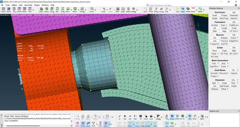
22. Release the mid surface FEA to incorporate it into the FE sheet
23. Define the spring by using the CBAR command and install a CBAR element to replace the spring.
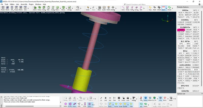
24. Release the voulemetric mesh from the vmesh deck and mirror the whole assembly by using transform --> copy option and selecting the mirror 3-point plane.
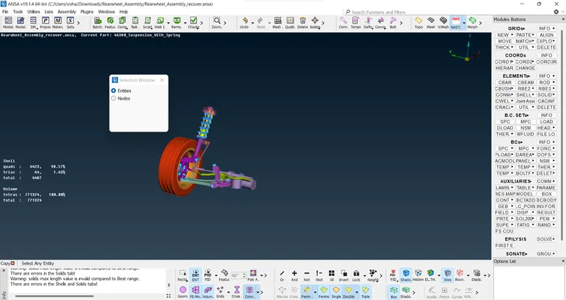
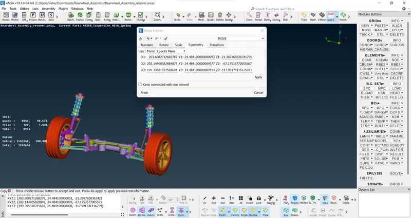
25. Paste the nodes of the transformed mesh at the interesction to make it a single volume using Paste --> auto --> selected elements and select the elements at the intersection.
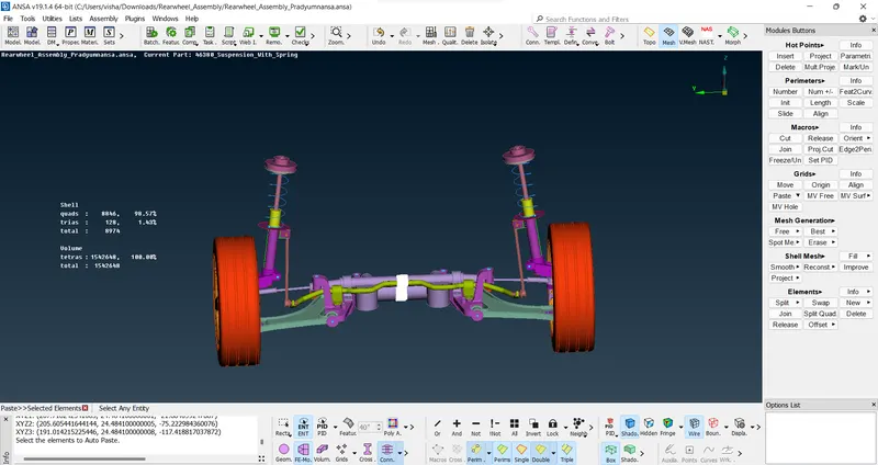
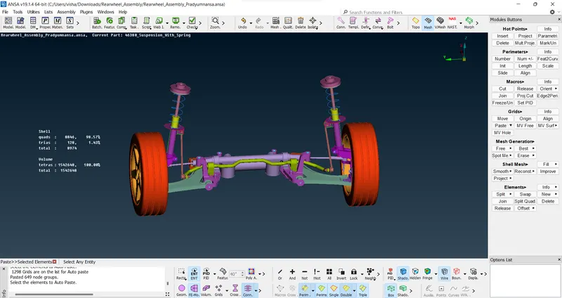
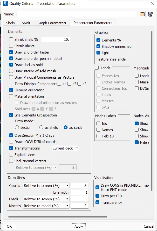
26. Turn on the draw shell as sold in line element cross section as solid option
Learning outcomes:
1. Gained knowledge of solving larger assemblies,
2. cleaning errors
3. Working with a large number of components and how to mesh different volumes and using differeent criterias
4. Gained perspective on which command to use in which scenario that will be most efficient
5. Learnt to solve multiple quality criteria models in a single assembly
6. Gained a better understanding of the connections and which connection to use in which scenario
7. Overall knowledge of a working assembly and how to prepare it from scratch for analysis.
Results:
Gained complete knowledge of the multiple decks of the ANSA module became familiar and comfortable with the multiple options available. I have gained a broader perspective of the whole software and the process and how to use it efficiently in different scenarios as can be seen from the above report where i showcased a lot of the skills needed in efficient ways.
I can now comfortably solve and generate assemblies and connections and negate the errors that are encountered during the process.
The model is attched in this link -