Assignment 3-2D Element Formulation Challenge
Objective:
1.Using the crash beam file from the previous assignment, change the run time to 55 ms.
2. Change the number of animation steps during simulation to a minimum of 25 and maximum of 60.
3. Run the base simulation without any modification to element properties.
4. At the end of the simulation, do the energy error and mass error checks and determine whether results would be acceptable.
5. If acceptable, Plot rigid wall forces, internal energy, hourglass energy, contact energy, total energy of the simulations.
6. Change all the shell elements properties to recommended properties, save this as separate, rad files and run the simulation.
7. Follow steps 5 and 6.
8. Create a brief report comparing all the results from steps 5 and 6 for both simulations.
9. Comment whether there is any change in the results and why there is any change in the result.
Theory:
Hourglassing is essentially a spurious deformation mode of a Finite Element Mesh, resulting from the excitation of zero-energy degrees of freedom. It typically manifests as a patchwork of zig-zag or hourglass like element shapes, where individual elements are severely deformed, while the overall mesh section is undeformed.
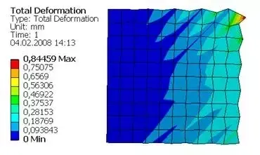
Consider a single reduced-integration element modeling a small piece of material subjected to pure bending
4
Deformation of a linear element with reduced integration subjected to bending moment M.
Neither of the dotted visualization lines has changed in length, and the angle between them is also unchanged, which means that all components of stress at the element's single integration point are zero. This bending mode of deformation is thus a zero-energy mode because no strain energy is generated by this element distortion. The element is unable to resist this type of deformation since it has no stiffness in this mode. In coarse meshes this zero-energy mode can propagate through the mesh, producing meaningless results.
How is hourglassing diagnosed?
By optical inspection of the mesh deformation, increasing its scale factor if necessary. But most reliably by directly comparing the energy contained in the zero energy modes (hourglass energy) with the internal energy of the system. Hourglass energy should not exceed 5% of internal energy. This is done by plotting the energies from history data.
How is hourglassing addressed?
- By inserting an artificial stiffness to the hourglass deformation modes (the default way utilised in static/quasistatic problems).
- By inserting an artificial viscosity (preferred for dynamic and high velocity impact problems).
- By using fully integrated elements.
- By refining the mesh.
Procedure:
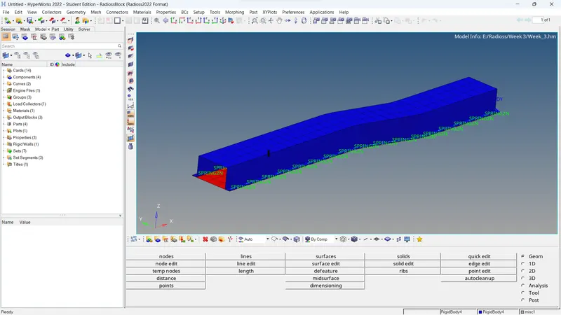
1. Input the geometry
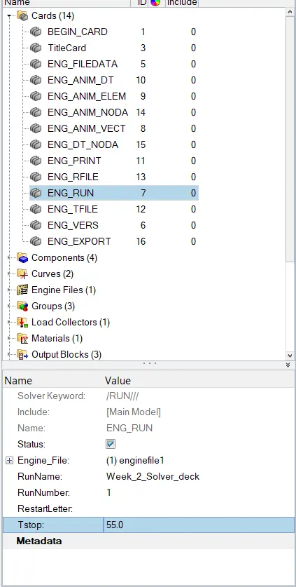
2. Open the Cards folder menu, go to ENG_RUN card and change the run time of simulation (Tstop) to 55ms
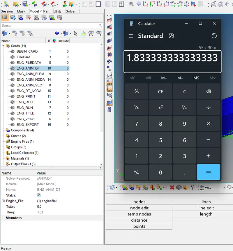
3. Select the numer of animation steps you want for example 30, now divide the run time with the number of animation steps to acquire the frequency of animation steps
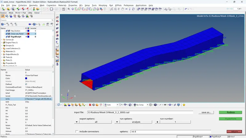
4. After the required steps, go to the analysis tab and select RADIOSS, select the input file and type -nt 4 in options panel to enable all 4 cores of your system to participate in the analysis
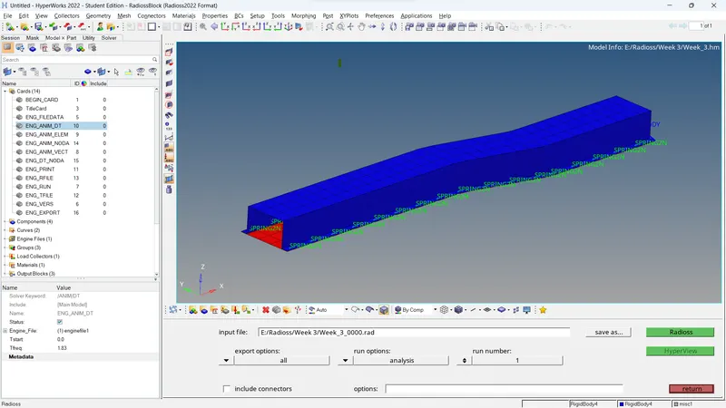
5. Run the simulation
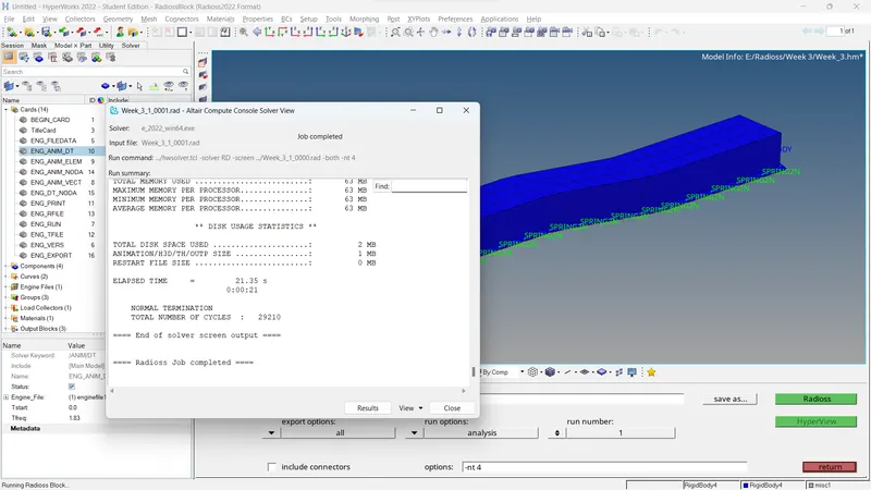
6. Check the output file termed as filename.0001.out and check for the energy error rate and mass error
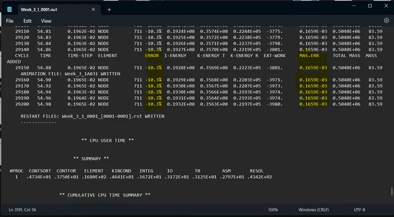
As the error rate is -10%, it is acceptable as the threshold is -15%.
7. Now check the simulation animation
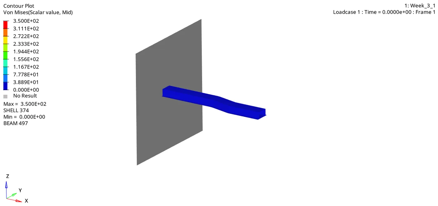
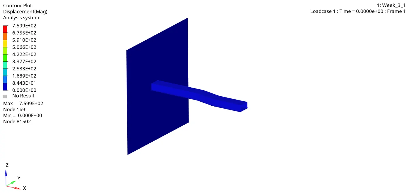
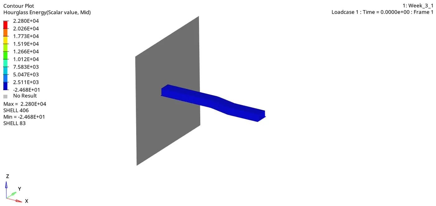
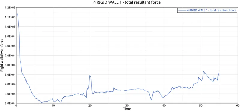
8. we can go ahead and plot the energy variables and Rigid wall forces, open hypergraph 2D for opening the .T01 file
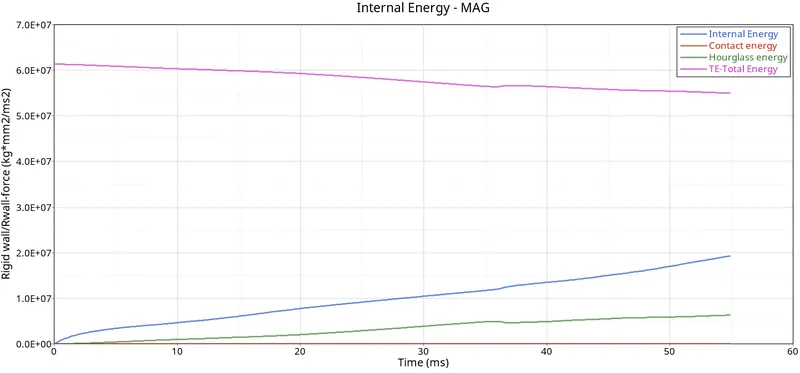
The graphs:
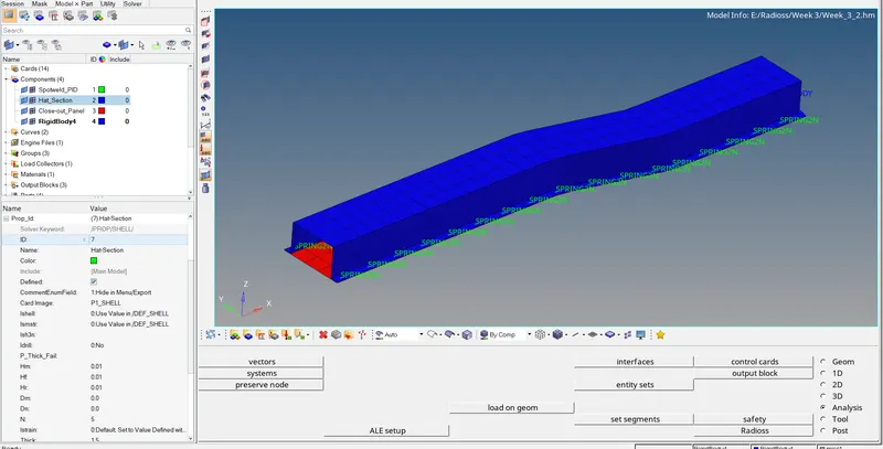
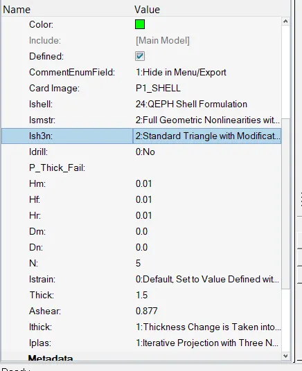
9. Now we have to repeat the same process but alter the shell element properties to recommended values to achieve better results
This can be done by going to the component card in the Hypermesh solver,
10. Run the simulation
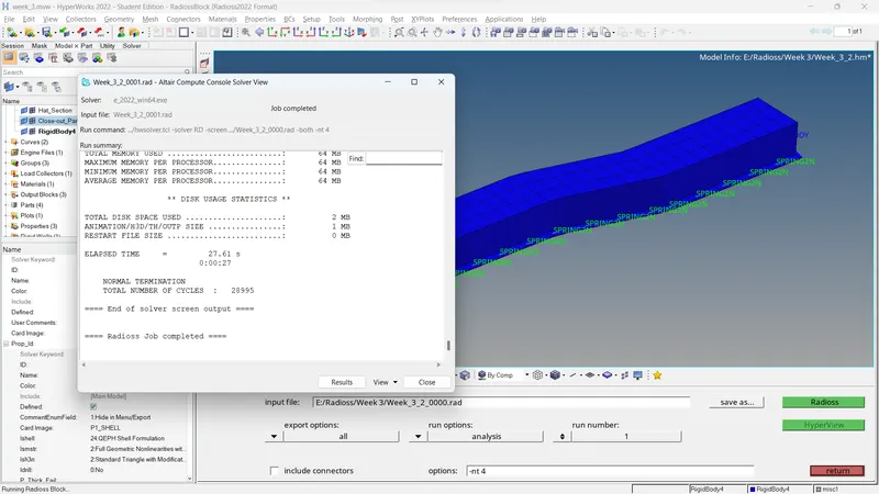
11. Check the output file
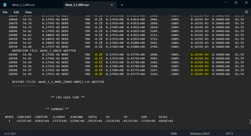
As evident, the error rate is almost nominal and very ideal
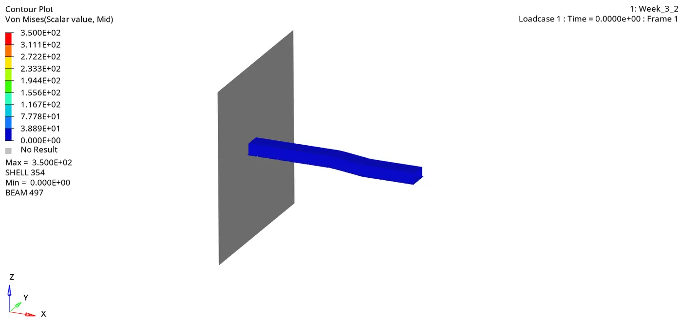
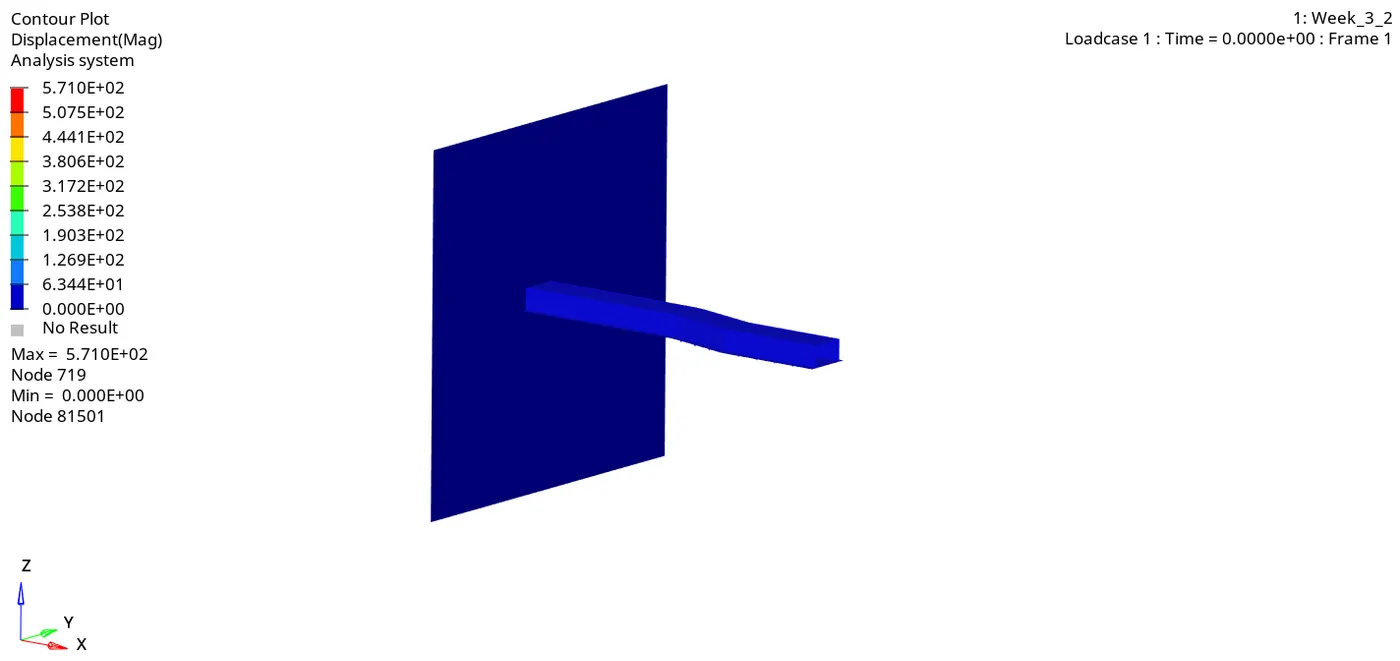
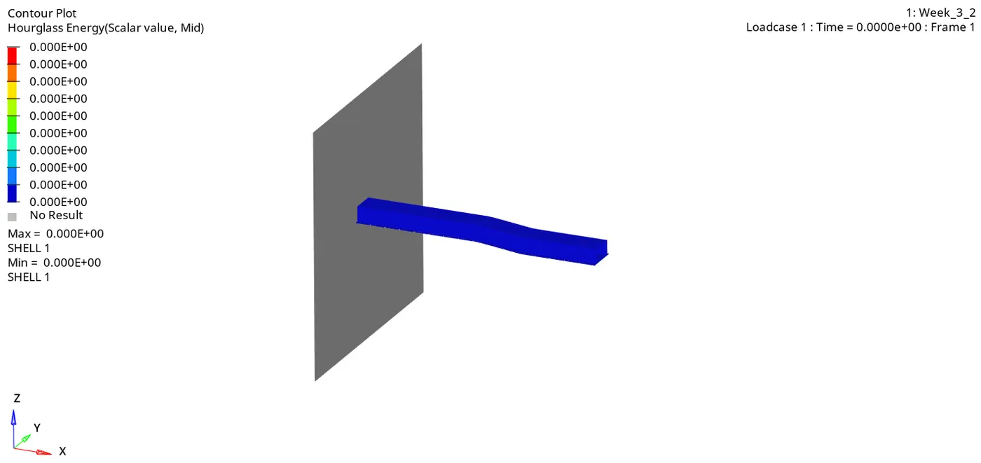
12. Check the animation
13. Plot the global variables
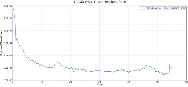
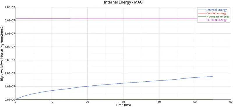
14. The major difference is the reduction in hourglass energy as using recommended shell properties have negated the hourglass effect
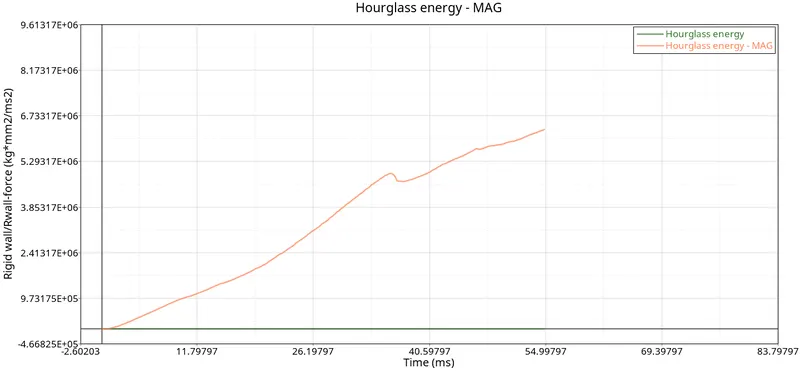
Hence the total energy in the recommended case is not hindered due to no loss of energy as hourglass energy while the TE of 1st case mentioned as MAG can be seen declining. That's why energy error in 1st case is -10.3% and 0.1% in the recommended settings case.
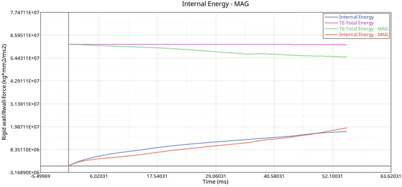
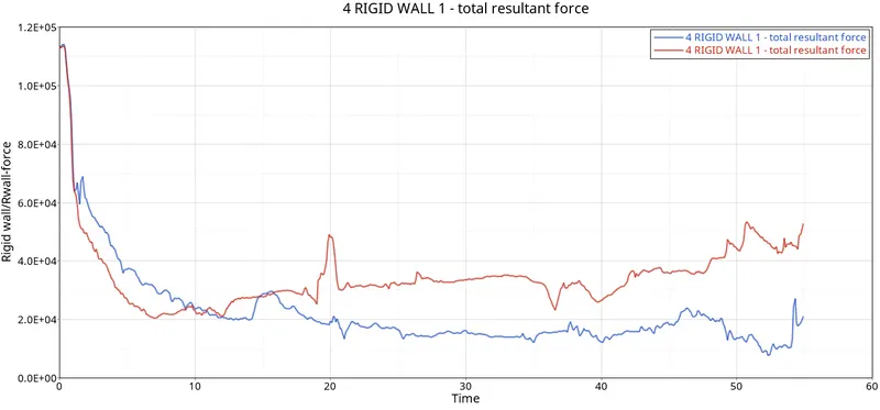
Also, in the rigid wall forces, due to no energy errors or sudden energy spikes, there are no sudden bumps in the graph hence resulting in a more realisitic simulation (Blue graph is recommended settings)
Results:
Required simulations were carried out and it can be deduced that to reduce energy errors, it is best to use the recommended settings as they drastically reduce the effficiency disparities such as Hourglass effect.
This is turn simulates more realistic energy variables such as internal energy, rigid wall forces, total energy and hourglass energy.
It also ensures that a realistic simulation animation is carried out as houglassing is negated thereby providing better movement of elements
Case 1
Case 2
Conclusion: It is best to follow recommended properties for best results
Learning outcomes: Knowledge of shell element properties, more familiarity with the properties section and the hypermesh software. Learnt how to read output results, graphs and deduce conclusion from them to increase efficiency.