Project 1
AIM Route the Wiring harness on Given Engine and Prepare flatten view drawing in CATIA V5.
OBJECTIVE Route the Wiring harness on Given Engine and Prepare flatten view drawing in CATIA V5. Application of all Packaging rules, Industry best practices studied in this course shall be demonstrated in design. Apply Protection coverings as required.Prepare & Submit all necessary reports like clearance, Clipping/Clamping selection, Harness fixing requirements, Harness continuity, Assumptions if any along with CATIA 3D data.
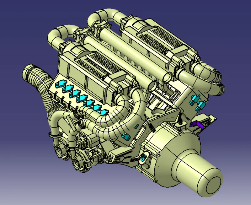
- The Given Engine is a 16 cylinder V-type engine, in these there are 16 fuel injector sensor (eight in one side), 1 coolant temperature sensor, pair of cam and crank shaft sensor, neutral and vehicle speed sensor so total 23 sensor.
- The plastic guiding channel used in this harness should be made of a material that can withstand at least 150 degree Celsius.
- The bend ratio for the all bundle segments should be 1.4
Assumption are
- Avoid routing near bolts or any sharp edge.
- Used clamps, clips or tie as per requirement to avoid buldge and fouling of harness to shape edge and provide posiive fix.
- Give additional slack if needed. 5-10% slack is sufficient.
- Ensure minimum clearance to heating surface like exhaust manifold or turbocharger line alteast to 200mm.
- Ensure minimum clearnace to coolant, brake, fuel, hydraulic line and dynamic part to 50mm
- Minimum distance between two branch points should be at least 50mm.
- Minimum distance between clip and branch point should be at least 25mm.
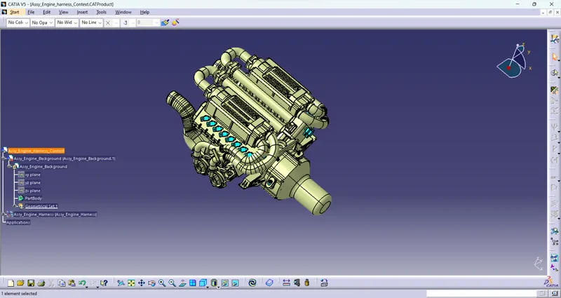
Creation of product File and add Backgroung Context File in Electrical assenbly design workbench.
- Create product file name "Assy engine Harness Context" and then add two product components first Assy engine background and other Assy engine harness.
- Now add the engine Part file to Assembly Engine background product component.
Electrically Define the all required connectors and manually locate to their places.
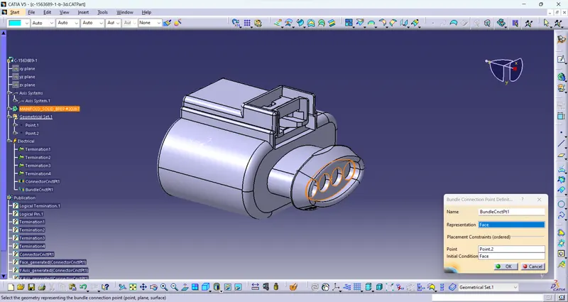
- Bundle Entry Point of connector C-1563689
- Connector Entry Point of Connector C-1563689
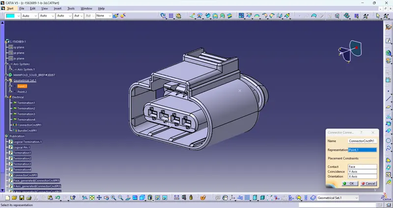
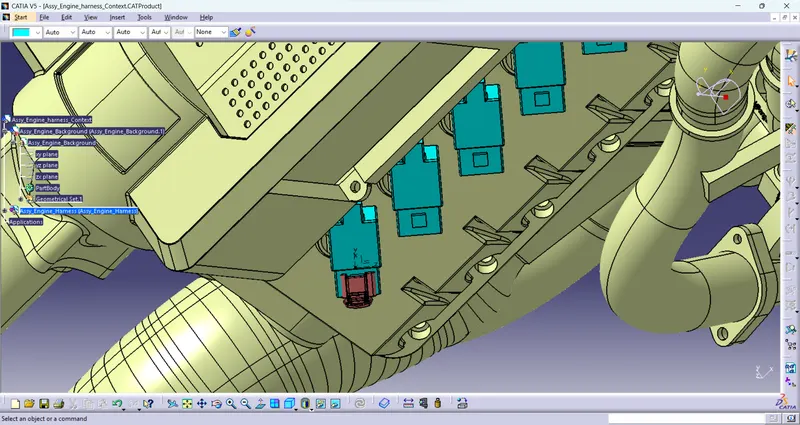
Located the connector to engine
Similarlly placed the all 16 fuel injector sensor coupler to their place.
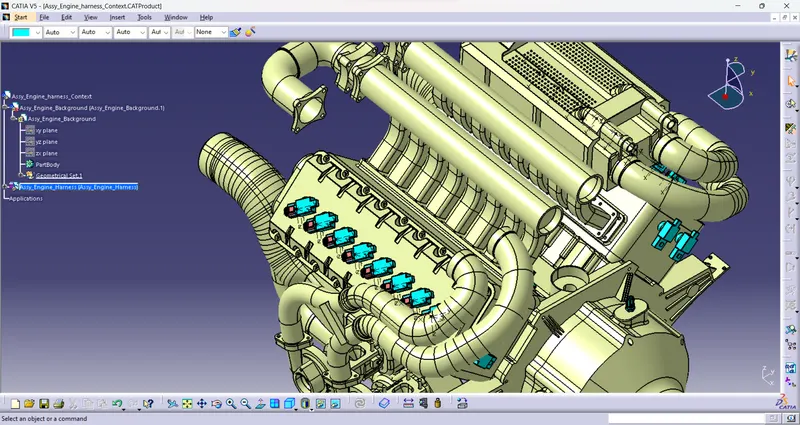
Now placed the electrically define cam sensor connector to their place.
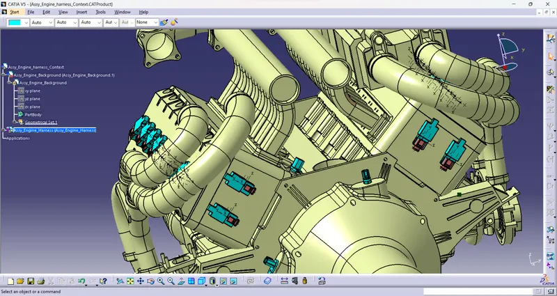
Simillarlly placed the Coolant temperature, neutral and speed sensor.
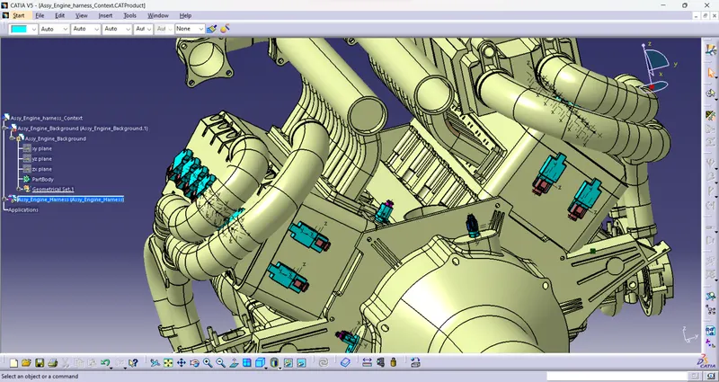
Now add and placed the L Bracket on the engine side for proper roting the harness bundle.
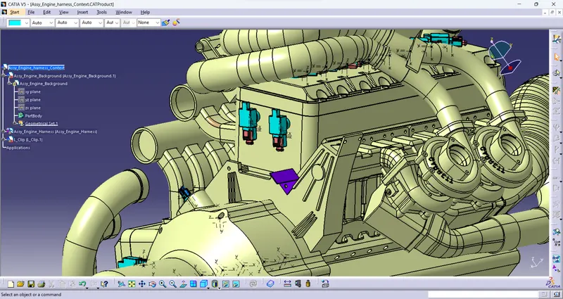
Add Connector Clip as Cavity on L Bracket
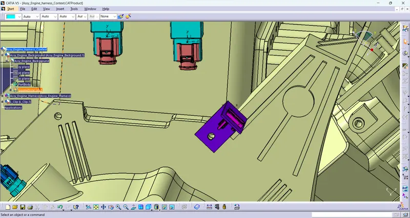
Now connect the electrically define inetrsection connetor to the cavity by with Electical harness assembly .
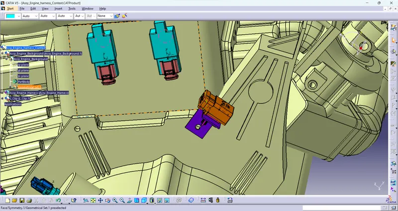
Add 3 C-Clamp on engine for routing of main harness bundle.
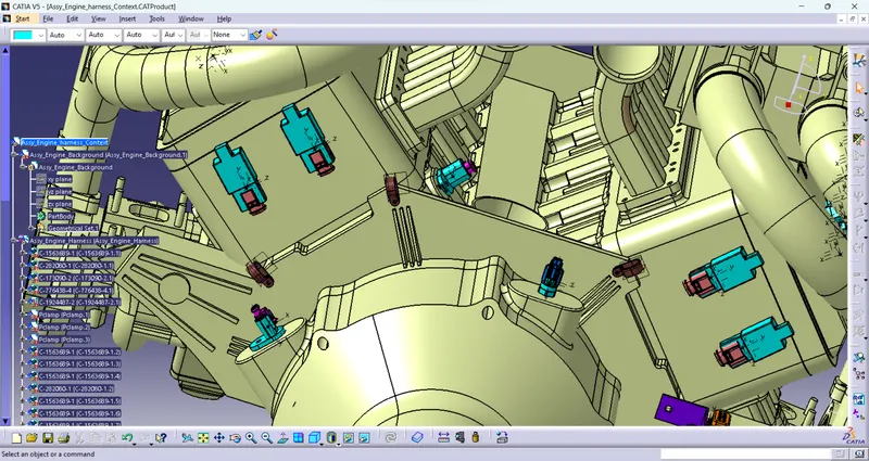
Creating Harness Bundle segment by multi branchable document Command in Electrical harness assembly workbench.
Now From Intersection connector start the bundle routing along C-clamp to 16 fuel injector sensors, coolant sensor, two pair of Cam and crank sensor, neutral and vehicle speed sensor.
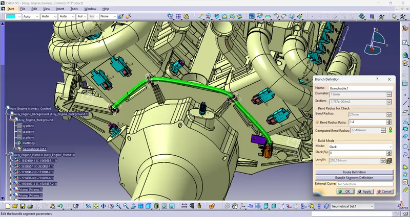
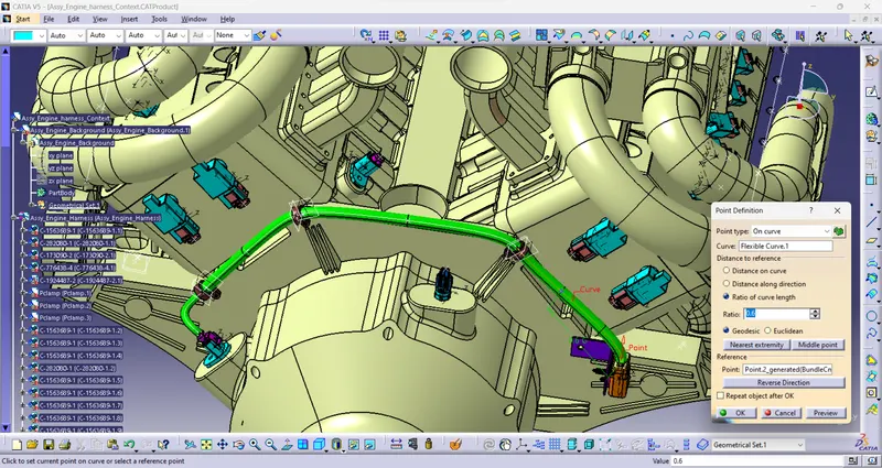
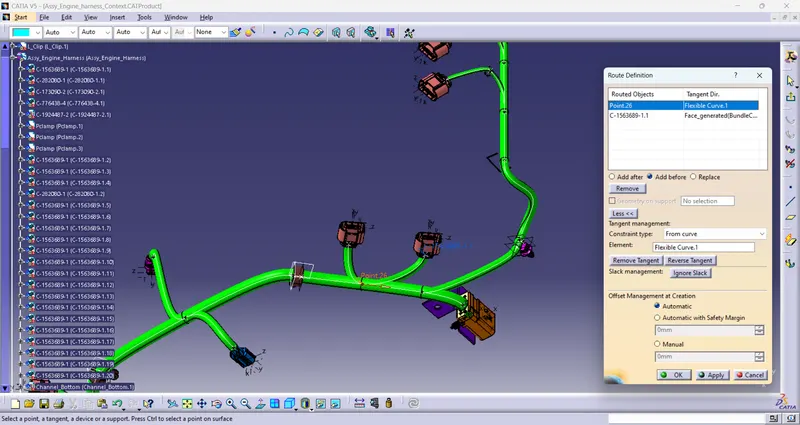
Now add the electrical define plastic guide channel anf furr tree clip for guide the harness near engine fuel injector on both side from main harness branch.
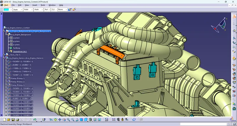
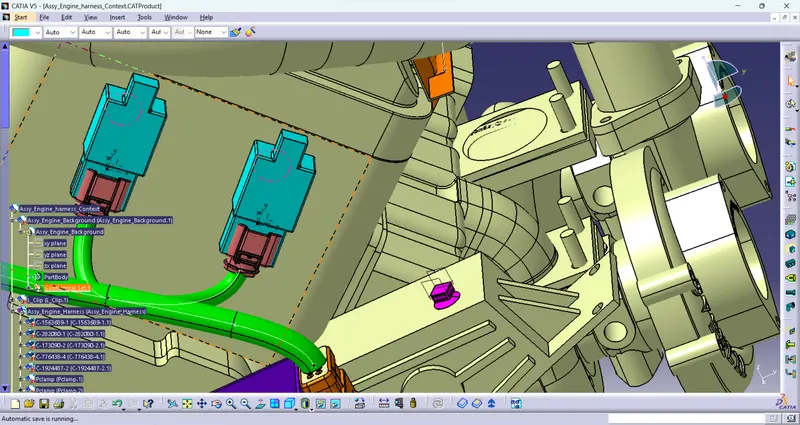
Now create a bundle segment from the main to plastic channel along furr tree clip.
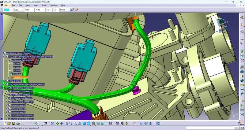
Create bundle segment on plastic channel through cruve option.
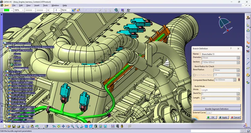
and then to each fuel injector sensor.
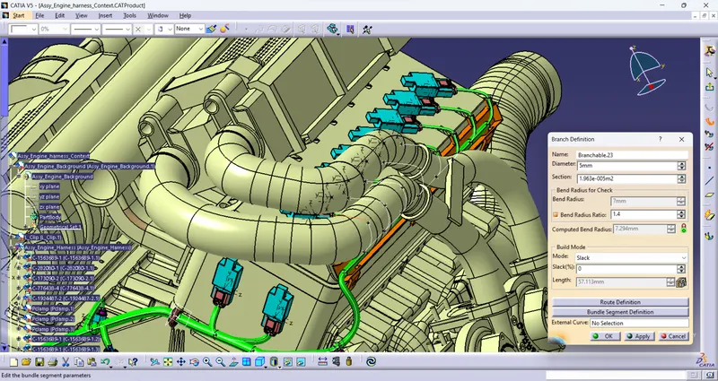
Similarlly create the other side of engine fuel injector.
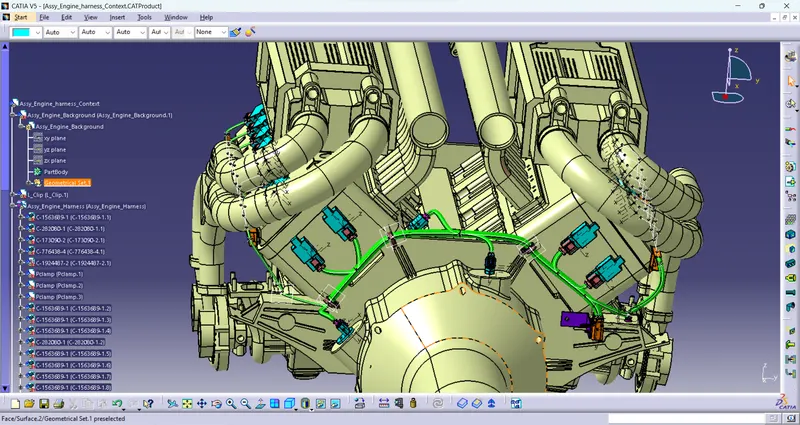
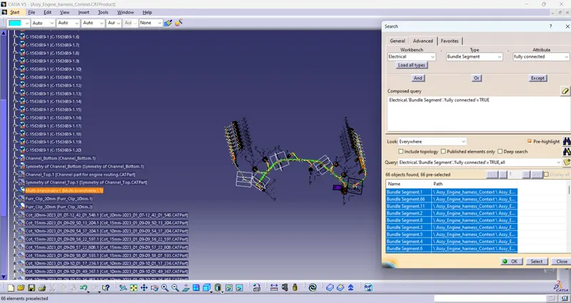
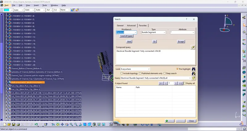
Check the bundle continuity
- Select Edit>Search>Workbench-Electrical,Type-Bundle Segment,Attribute-Fully Connected
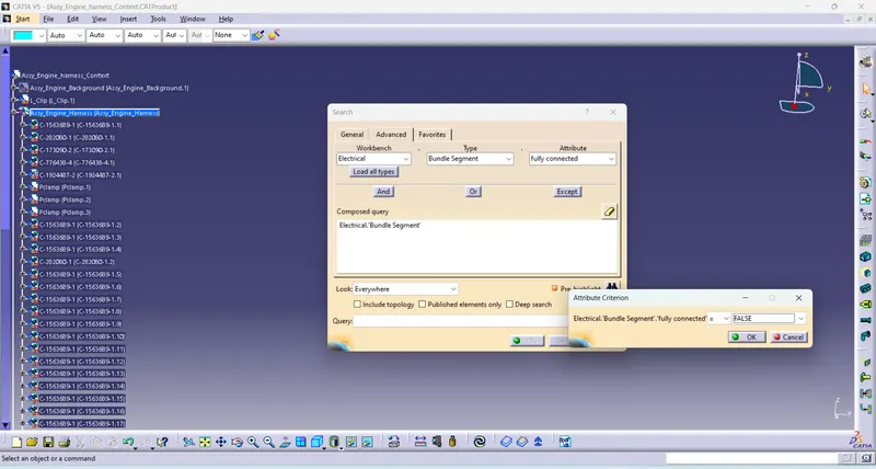
By selecting 'True' option will show all the connected bundle segments while selecting 'False' option will show all the non-connected bundle segments.
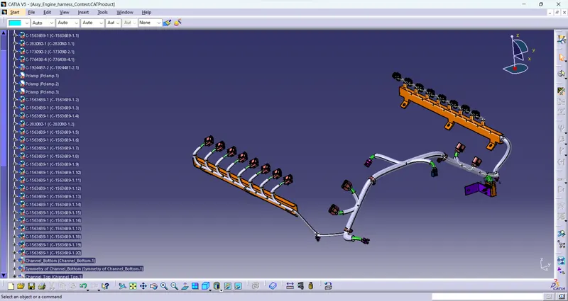
Now add the protective cover to the harness bundle by protectice covering command in Electical harness assembly Workbench.
Creating flatten view of the engine harness geometrical bundle assembly
In this step, for creating flatten view we have to work in Electrical Harness Flattening workbench of Catia V5. We should also make sure that the flattening file is saved in the same folder where other files of harness assembly are saved.
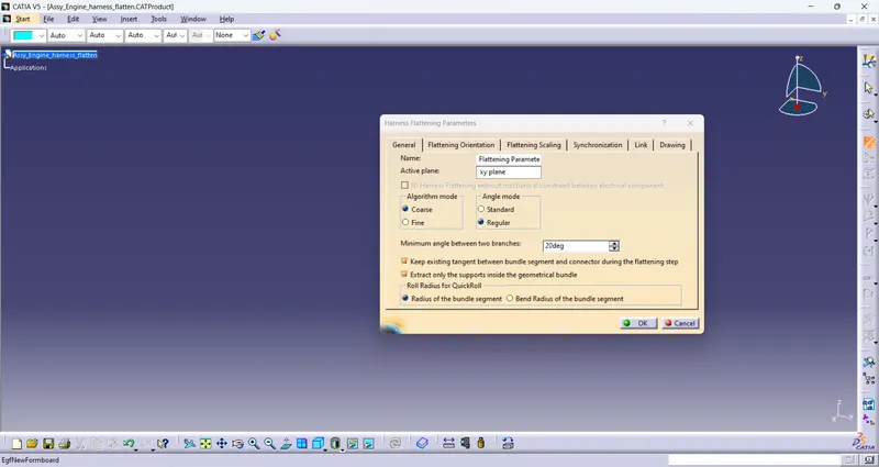
Before creating flatten view, first we have to define flattening parameters. Make sure that selecting 'Single line' for bundle segment and 'Double' line for protective covering.
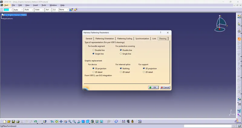
Now ext
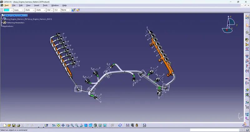
Select the flatten command along XY plane and select the all-bundle harness segment.
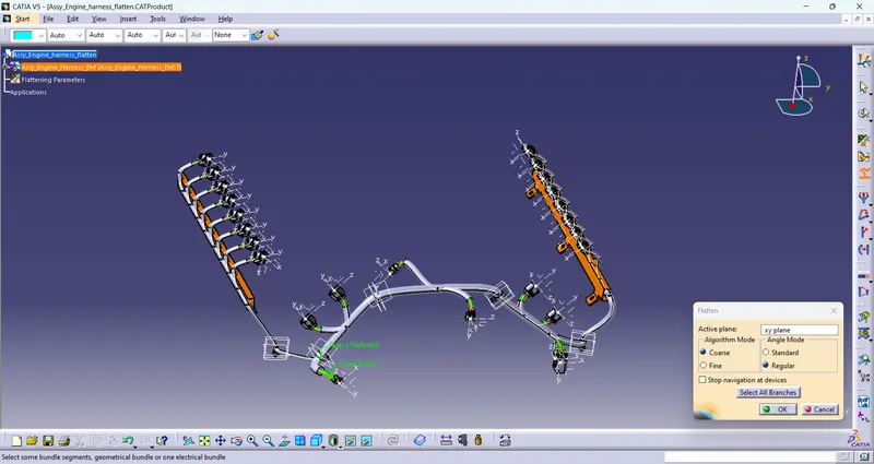
Through manipulator command like rotate and bend adjust the harness for better representation.
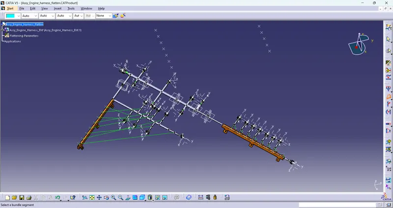
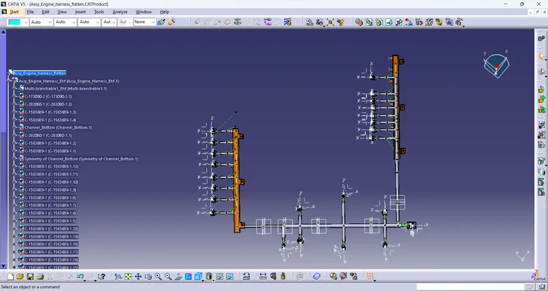
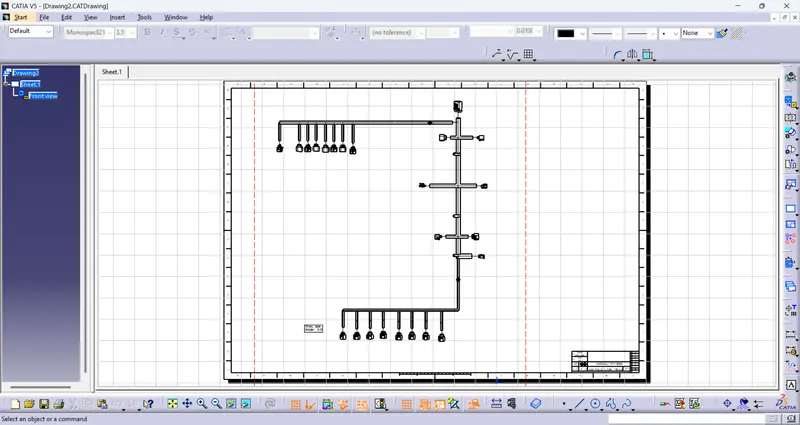
Creating a flatten view drawing for the wiring harness assembly use drafting workbench
Select front command in drafting workbench and then select the required front face of the flatten harness.
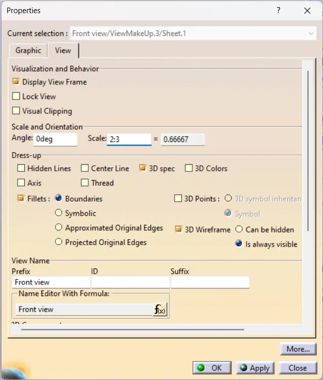
select the suitable scale size and 3D wirefarme as is always visible