Advanced Sheet Metal Design Using NX Cad Challenge_1_Casing Design
CASING DESIGN USING NX CAD
OBJECTIVE - Design a Sheetmetal casing using NX-Cad.
INTRODUCTION
Sheet Metal
Sheet metal is metal formed by an industrial process into thin, flat pieces. Sheet metal is one of the fundamental forms used in metalworking, and it can be cut and bent into a variety of shapes. Countless everyday objects are fabricated from sheet metal.
There are six major types of sheet metal material, each with its own unique advantages:
1. Alloy steel.
2. Stainless steel.
3. Carbon steel.
4. Tool steel.
5. Galvanized steel.
6. Aluminium.
Sheet metal is used in car and truck bodies, airplane fuselages and wings, medical tables, roofs for buildings (architecture), and many other applications. Sheets of iron and other materials with high magnetic permeability, also known as laminated steel cores, find applications in transformers and electrical machinery.
In this project, I designing a Casing of Sheetmetal using Siemens NX-Cad software.
DESIGN METHODLOGY
In this project, we use various sheetmetal operations or features like Tab, Cutout, Bend, Dimple, Beed, hole etc to design a casing.
First set the Global Parameters like Material Thickness, bend radius, Relief Depth and Relief Width to 1mm and Neutral factor value to 0.33.
Flow chart of design casing in NX-Cad
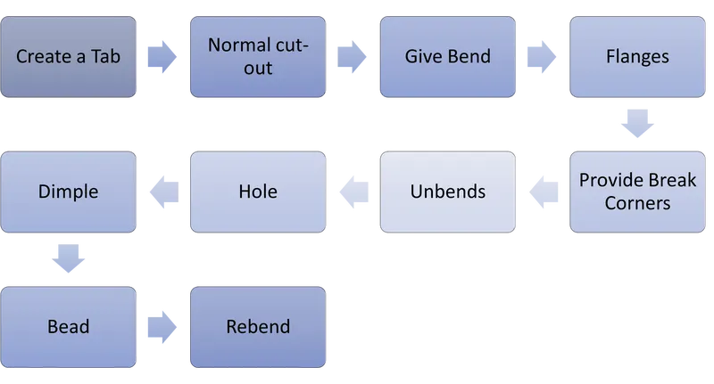
DESCRIPTIONS OF ALL FEATURES WHICH ARE USED TO DESIGN THE CASING
- Sketch Creating a different shape using sketch tool like line, spline, rectangle, circle, arc etc and provide dimensions and constraints.
- Tab To create a based feature by extruding a sketch along to a vector to providing thickness, and adds, materials to planer face.
- Normal Cutout This feature cut material by projecting the sketch onto the model
- Bend This feature provide bend on the model with the help of sketched line.
- Flange To Add a flat flange at an angle to a planer face and add bend between two
- Break Corner To create chamfers or smooth corner of the Tab and Flange.
- Unbend This feature flattens the bend and material adjacent to the bend.
- Hole To create a hole on the solid bodies with options of countersunk, counterbored, thread.
- Dimple It is a punch feature in which lift area of the model inside a sketch that simulate a stamping tool
- Bead It lift material along the contour of sketch that simulate a stamping tool.
- Rebend Restore the unbend feature to its previous bend feature along with any feature added after the unbend feature.
- Flat Pattern Create a Flat pattern feature from the formed Sheetmetal part
- Draft To Convert a 3D model to 2D drawing with annotation
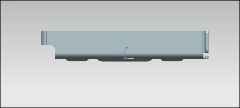
Front View
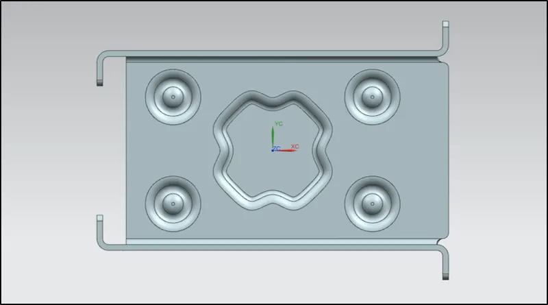
Top View
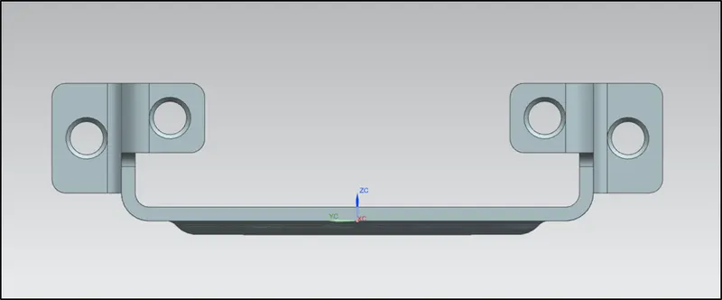
Side View
Back view
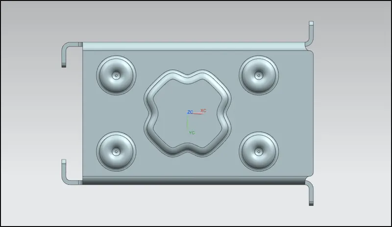
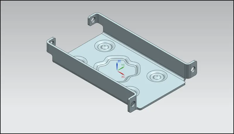
Isometric View
Drawing Sheet
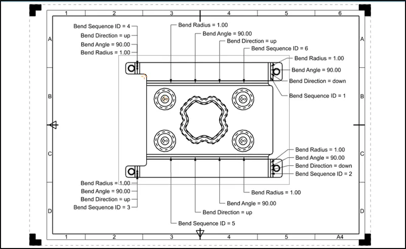
CONCLUSION Design a Sheetmetal Casing by using different features of Bend, punch, Corner etc in Siemens NX-Cad and also draft the model in A4 sheet at 2:1 scale.