Week 8 - Challenge 4 - Bumper
OBJECTIVE Create the Bumper Plastic component through the given Class-A surface
- Creating tooling axis
- Class B and C surface
- Perform draft analysis on Class A surface and final component
INPUT Given Class A surface and take the thickness of the components 3mm
Tooling axis: Tooling axis is the direction at which core and cavity opens.
Procedure for creating tooling axis
- First check the connectivity of the given Class A surface by using the Boundary or Join feature to visualized and repaired the open edges of the surface.
- And then, analyse visually the best suitable plane or surface for tooling axis.
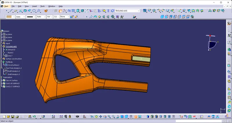
- After that, extract a surface from CLASS-A Surface and then create a centre point on the surafce for the axis on the point.
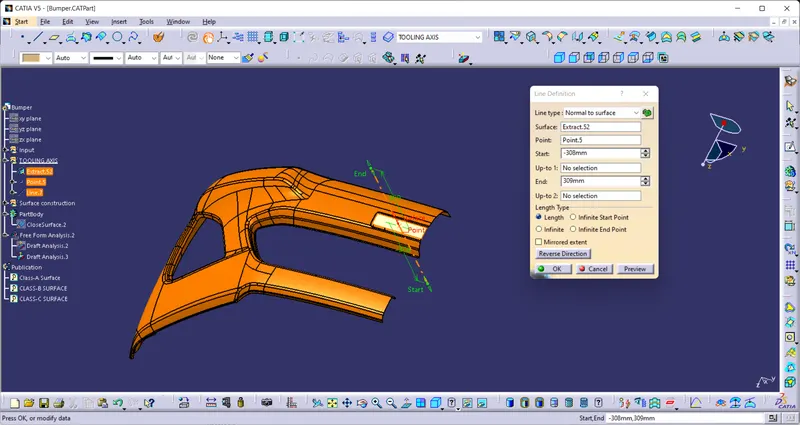
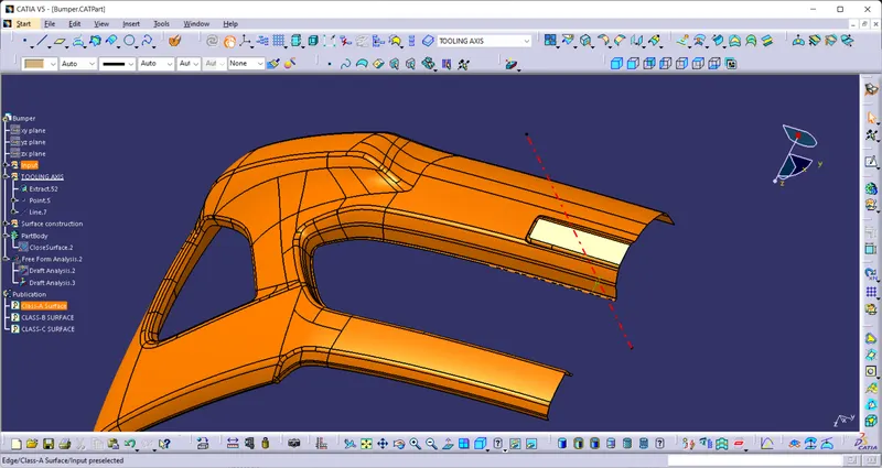
then create a tooling axis from by using Normal surface line command on the extracted surface at the centre point.
Draft Analysis Darft analysis is a tool perform to check the product easliy removed from the core and cavity. In other word in draft analysis we check the product easily clear the minumum draft (3 degree).
Screenshots of the Draft analysis report for the given Class-A surface
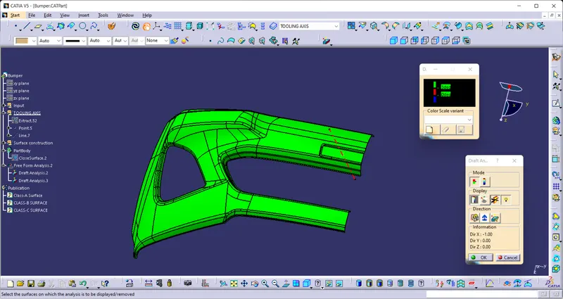
Screenshots of the Draft analysis report for the final plastic component
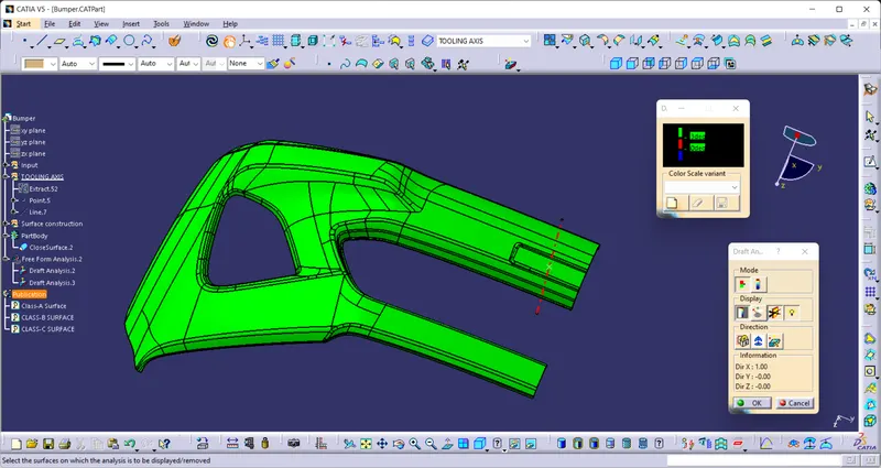
Screenshots of the solid model with the proper color code of the draft angle in various orientations
- Isometric View
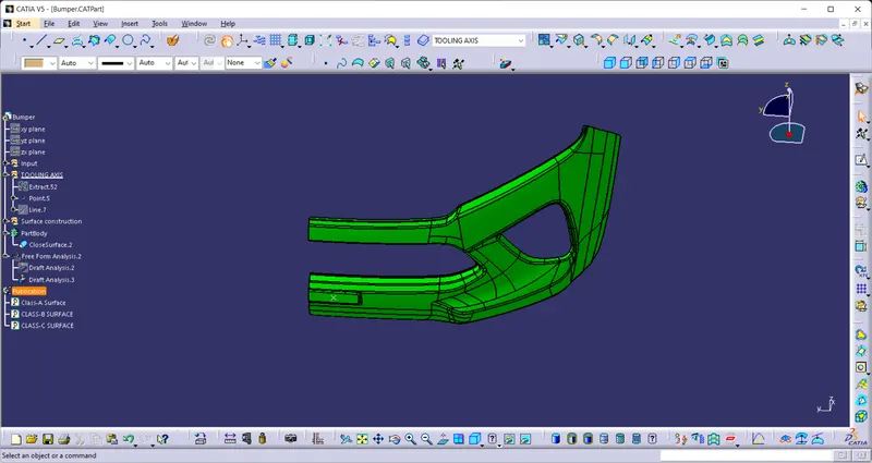
- Front View
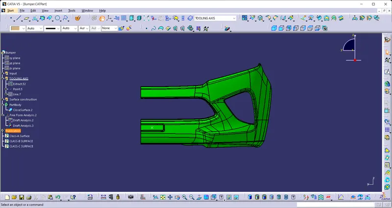
- Side View
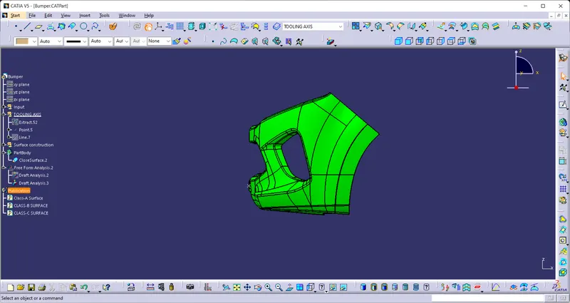
- Top View
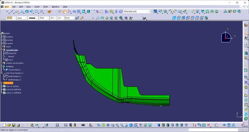
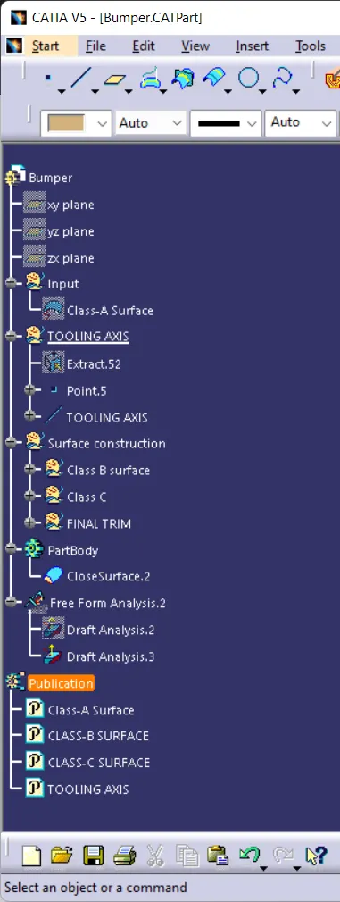
TREE STRUCTURE OF BUMPER