Week 9 - Attachment Feature Creation (Ribs & Screw Boss) - Challenge 1
AIM Create Rib and Screw boss for the door handle considering design rules
INPUT Given Class A surface of door handle with the thickness of the component 2.5 mm.
Procedure for the projects
- Creating the tooling axis
- Draft analysis of Class A surface
- Creating Class B surface
- Creating Class C surface
- Surface and solid body
- Draft analysis of Solid body
- Engineering features Rib and Screw boss
- Draft analysis of Solid body with engineering features
Tooling axis creation
Procedure for creating tooling axis
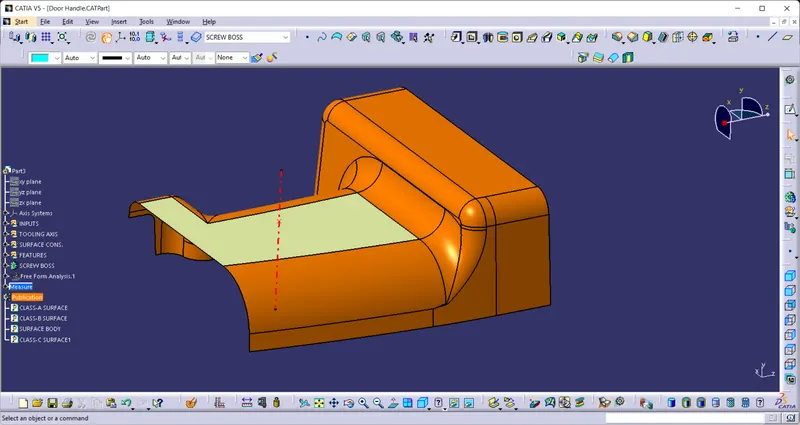
- First check the connectivity of the given Class A surface by using the Boundary or Join feature to visualized and repaired the open edges of the surface.
- And then, analyse visually the best suitable plane or surface for tooling axis.
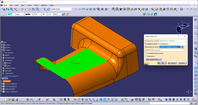
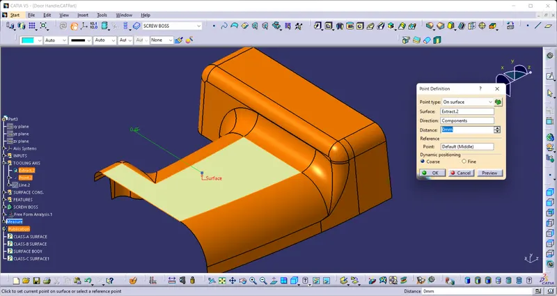
- After Extract surface from class A surface, create a centre point on surafce for creating the axis on the point.
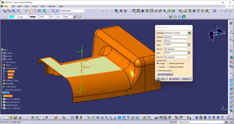
- Create a line at the centre points by using normal to surface type from line feature.
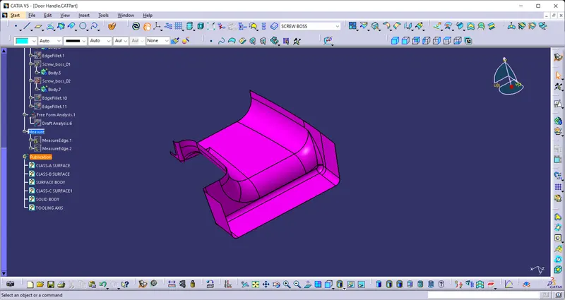
Screenshoot of Class-B surface
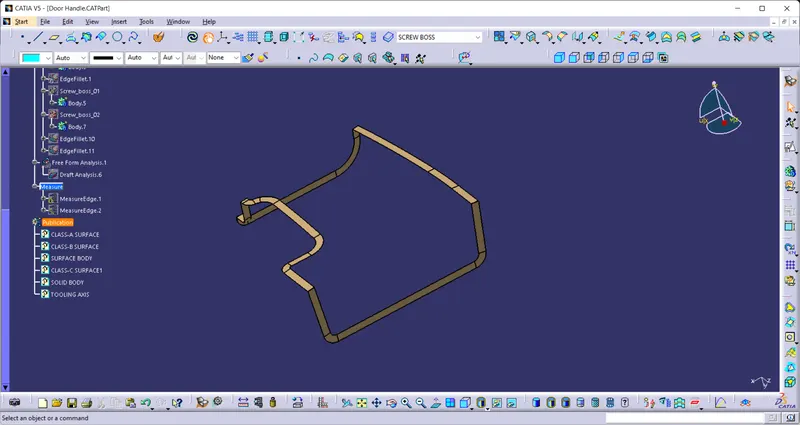
Screenshoot of Class-C surface
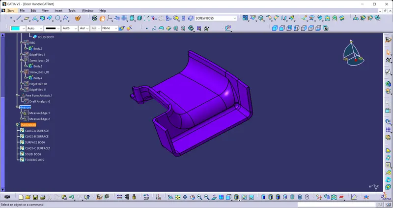
Screenshoot of Surface body
Creation of Engineering features
- Rib
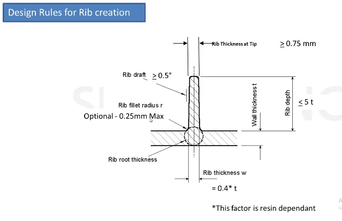
Rib provides an economical way to increase stiffness and strength to the mould parts without increasing the overall thickness of the wall. It is thin protrusion that extended perpendicular from the wall.
Design considersation of the Rib
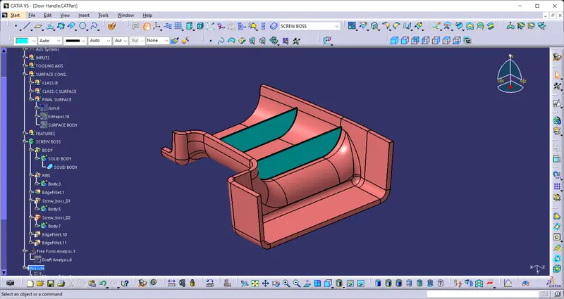
Screenshot of both Rib
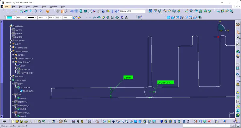
Rib root thickness analysis
To check the Rib root thickness, first take perpendicular intersection across the body and the Rib and then have to sketch a circle which tangent to the Rib base or root area by using tritangent type circle. The value must be within 30% greater of the wall thickness.
- Screw Boss
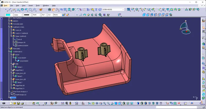
Screw boss are used as a point for attachment and assembly, most common in as cylindrical projection with hole design to receive screw or other types of fastening hardware.
Design considersation of the Screw boss
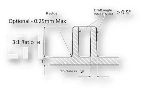
Screenshot of Screw Boss
Draft Analysis
Darft analysis is a tool perform to check the product easliy removed from the core and cavity.
In this project we analysis the draft angle of the Class A Surface And the plastic components with feature.
Screenshots of the Draft analysis report for the given Class-A surface
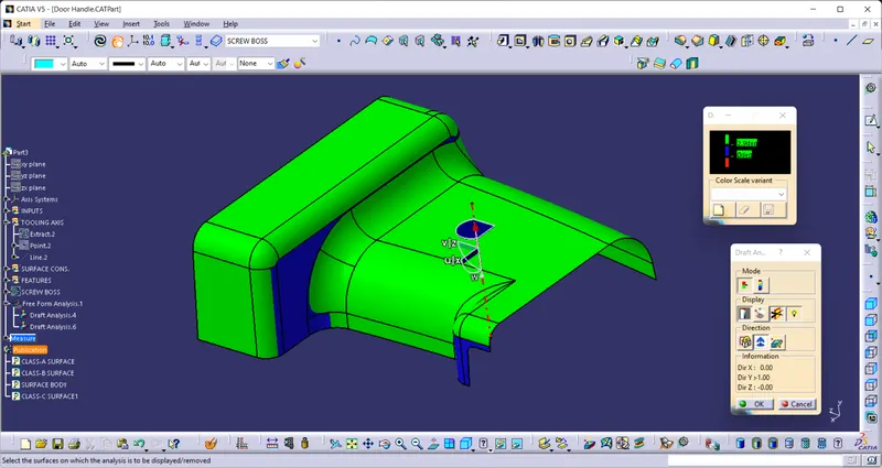
In the draft analysis of Class A surface of door handle, most of surface are green that means the surface has draft angle more than 2.9 degree and some surface has draft angle in between 3 to 1 degree which is shown in blue color and there is not negative draft surface here.
- Screenshots of the Draft analysis report for the given final plastic component with rib and screw boss
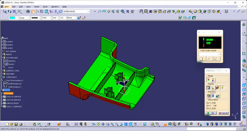
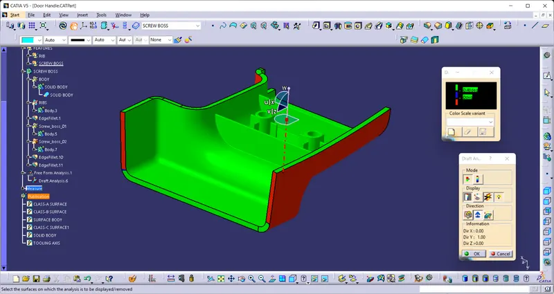
The draft analysis at draft angle 0.48 degree with the tooling axis to the plastic componenets engineering feartures like Rib and Screw boss show green which means it clear during production process, but some surface of left side of Class-C surface has negative draft upto -0.73 degree which show in red color.
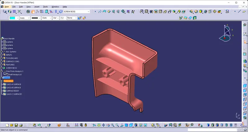
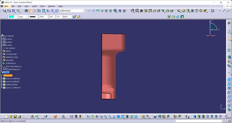
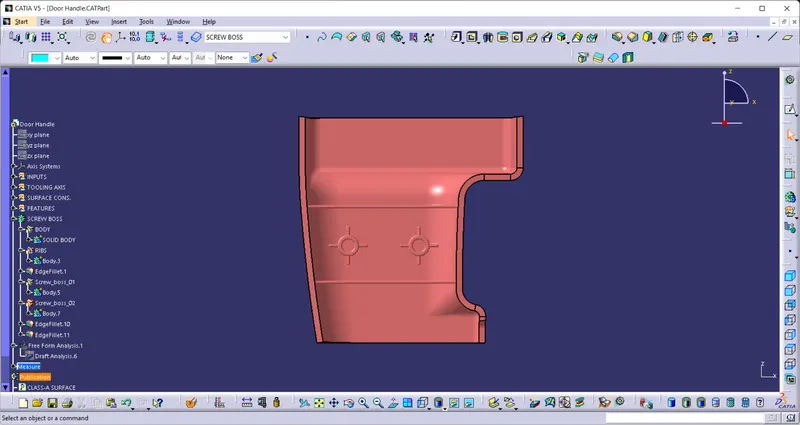
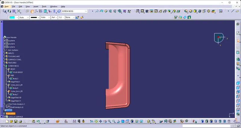
Screenshots of the completed design in various orientations
- Isometric View
- Front View
- Side view
- Top View
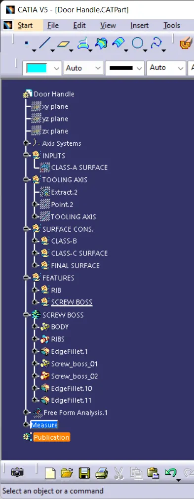
Tree structure of Door handle