Week 11 - Final project
AIM Development of a Door Trim panel
OBJECTIVE
Creation of CAD model considering following inputs as like in OEM and tier1 companies
- Class A surface
- Nominal thickness : Refer master sections
- Attachment strategy :
Find a attachment strategy for the door panel complete work.
Use Push pin with Dog house for Lower substrate – Door panel attachment
Use heat stakes for part to part attachment
Sequence of Operations to generate CAD Model of a plastic component:
- Extracting the input Class-A surface into different parts of Assembly.
- Looking for defects in Class-A surface.
- Improving Class-A surface by patching defects.
- Improving Class-A surface as per Master section.
- Creating Tooling Axis.
- Creating Class-B surface.
- Creating Class-C surface.
- Creating a Closed Body.
- Creating Dog House as per Master Section and OEM standard design Rules.
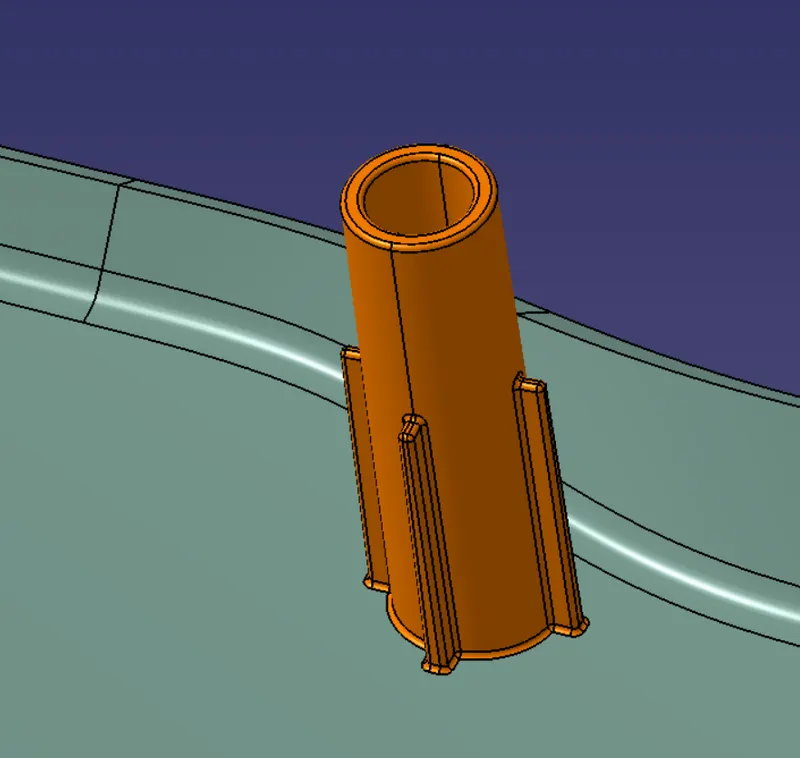
- Creating Heat Stake as per Master Section.
- Creating Locators as per requirement.
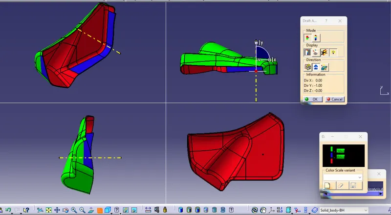
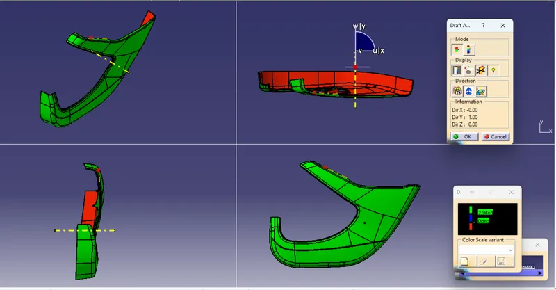
- Draft Analysis of each part and theirs B-side features
- Constraint Push Pins with Dog House
- Creating of Parting line of each parts
Class-A Surface:
A-class surfaces are those aesthetic/ free form surfaces, which are visible to us (interior/exterior), having an optimal aesthetic shape and high surface quality. Mathematically class-A surfaces are those surfaces which are curvature continuous while providing the simplest mathematical representation needed for the desired shape/form and does not have any undesirable waviness. Products are not only designed considering the functionality but special consideration is given to its form/aesthetics which can bring a desire in one’s mind to own that product. This is only possible with high-class finish and good forms. This is the reason why in design industries Class-A surfaces are given more importance. In automotive design, a class-A surface is any of a set of freeform surfaces of high efficiency and quality. Although, strictly, it is nothing more than saying the surfaces have curvature and tangency alignment – to ideal aesthetical reflection quality, many people interpret class A surfaces to have G2 (or even G3) curvature continuity to one another (see free form surface modelling). Class A surfacing is done using computer-aided industrial design applications. Class-A surface modellers are also called "digital sculptors" in the industry. Industrial designers develop their design styling through the A-Surface, the physical surface the end user can feel, touch, see etc.
Class-B surface:
Class-B surfaces are the secondary surfaces that can be seen sometimes, but are less important, such as the inside of your glovebox, ash tray, etc. These must be smooth and "error-free" as well, but are not held to the standards that class-A surfaces are.
Class-C surface:
Class C surfaces are the backside surfaces that can have tool marks, flash and other imperfections without hurting appearance, function, etc.
Draft Analysis:
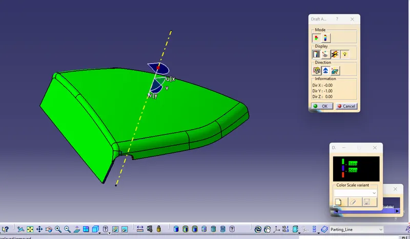
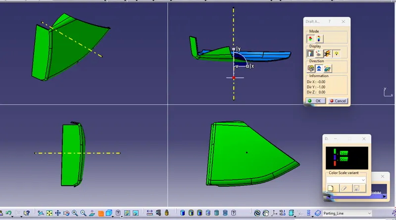
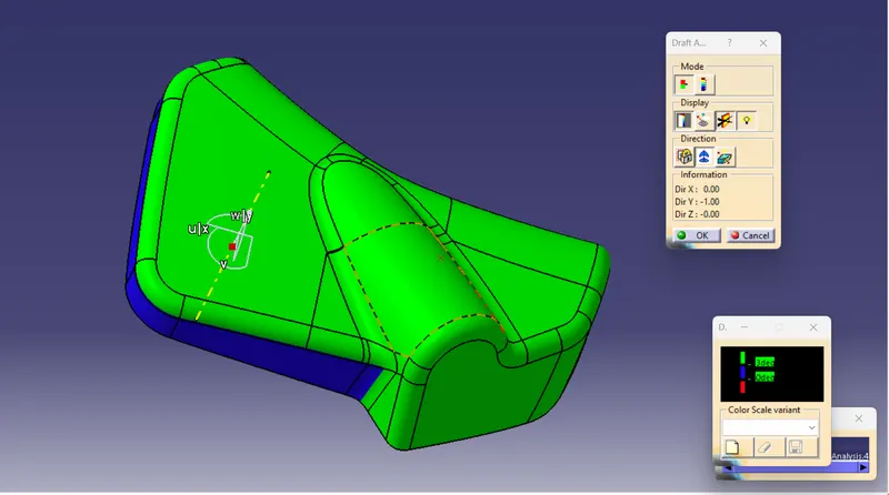
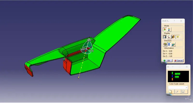
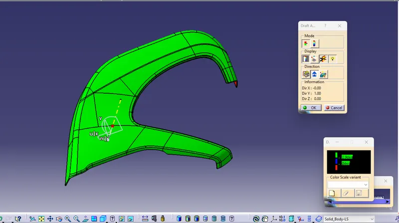
The Draft Analysis command enables you to detect if the part you drafted will be easily removed. This type of analysis is performed based on colour ranges identifying zones on the analyzed element where the deviation from the draft direction at any point, corresponds to specified values.
Tooling direction is the main consideration for plastic part and mould parts because it defines the movement of the mould part and the possibility of the plastic part coming out from the mould part (Core and Cavity).
- In Molding, machine arrangement is given to open the mould along a direction which is known as Tooling Direction.
- In other words. The mould is built from two separate halves (Core and Cavity) and tooling direction basically defines the direction of mould pulls apart.
- Tooling direction is known as primary direction.
DESIGNING OF PLASTIC COMPONENT FOR GIVEN DOOR TRIM PANEL CLASS-A SURFACE:
Door Trim Panel consists of following Components.:
- Map Pocket
- Bottle Holder
- Arm Rest
- Lower Substrate
- Heat stakes and Locators
- Flanges
- Dog Houses
Map Pocket
Map pockets can be created integrally within the door trim panel by forming a projection region outwardly towards the passenger compartment and then providing a separate panel attached to the rear outboard surface of the trim panel. This type of map pocket protrudes into the passenger compartment. Another type of map pocket such as a recessed map pocket can also be formed within the door assembly such that the storage compartment of the map pocket is generally located between the trim panel and the outer metal panel of the vehicle door. An aperture in the door trim panel defines the opening into the map pocket. Generally, these types of map pockets are formed by a separate map pocket assembly which is fastened to the rear surface of the trim panel. The map pocket assembly includes a front portion and a separate rear portion which are connected together to form the map pocket assembly and define the storage compartment. The rear portion defines a rear wall of the map pocket assembly. The front portion defines a lower front wall and a pair of side walls. The region above the lower front wall is generally open to provide access to the storage compartment of the map pocket. The map pocket assembly is then attached to the rear surface of the door trim panel such that the opening of the map pocket is generally aligned with an opening formed in the door trim panel.
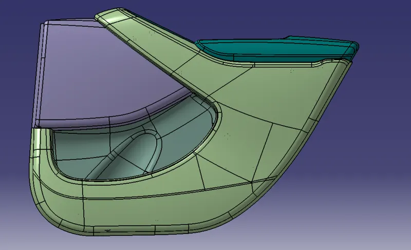
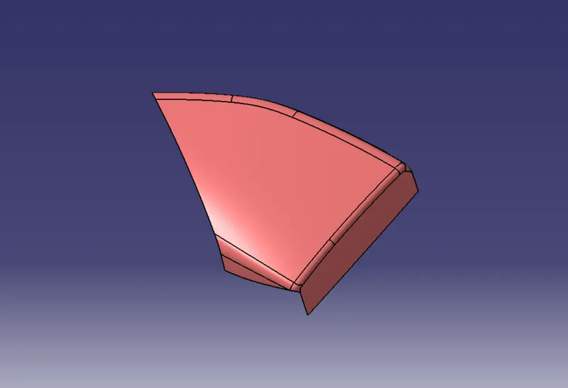
Master Section and Class A Surface of Map Pocket
Class A surface
Check the continunity of the surface.
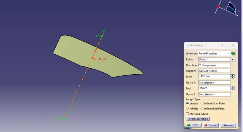
Creating a tooling axis of the surface.
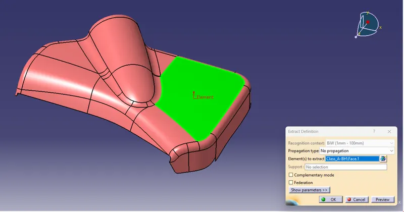
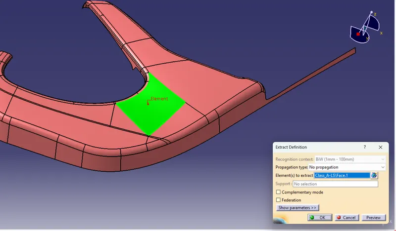
- Extract the surface from the class A surface.
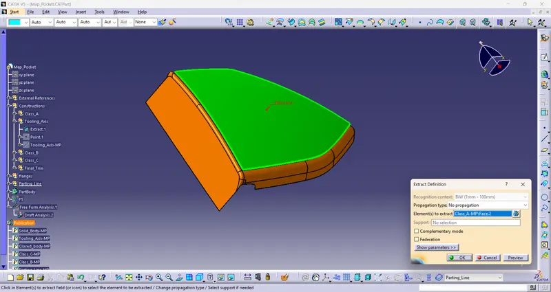
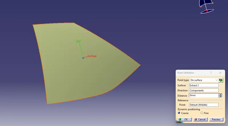
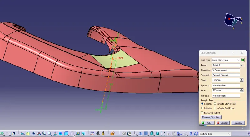
create a point on the surface by on surface option to create line for the tooling axis.
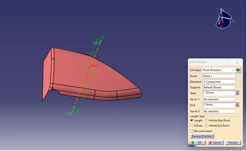
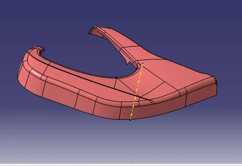
Using Point-Direction option to create the line for the tooling axis along Y axis.
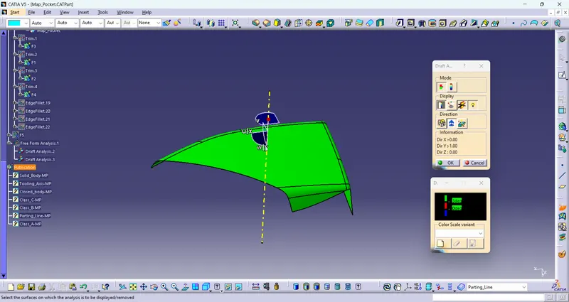
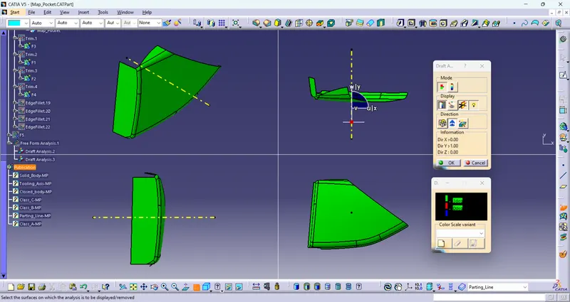
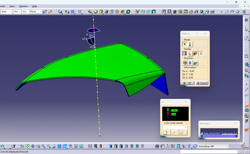
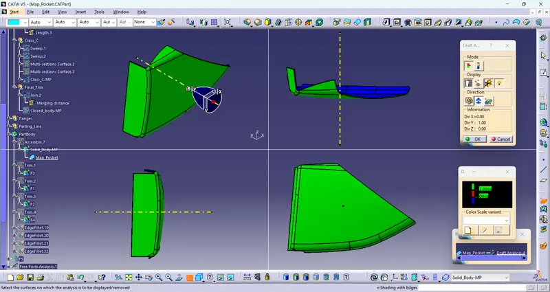
Now check the draft analysis to the surface.
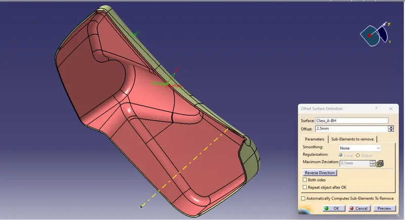
Creattion of Class B surface
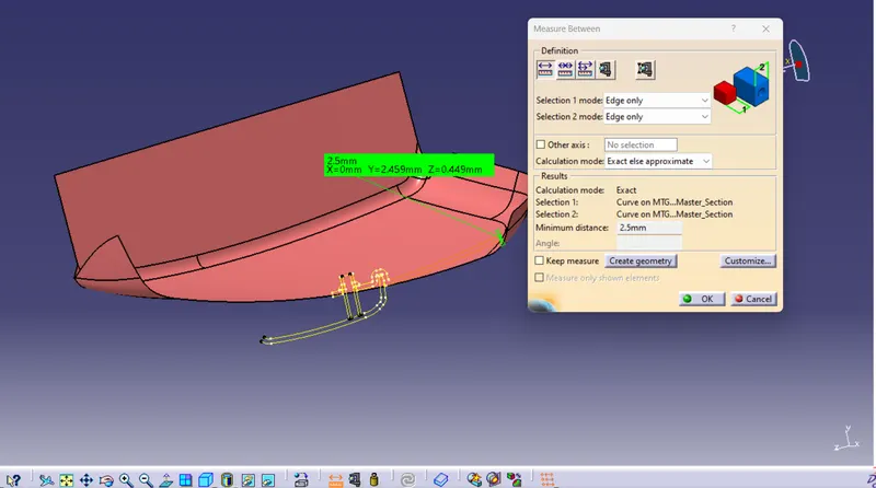
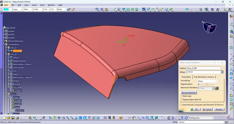
- Offset the class A surface to 2.5mm as per mastersection to create class B surface.
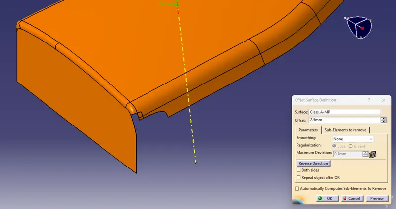
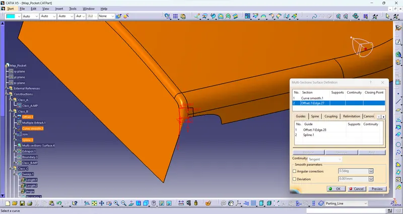
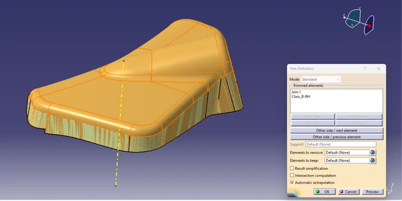
- Create a surface to the patch by using multi-section surface command.
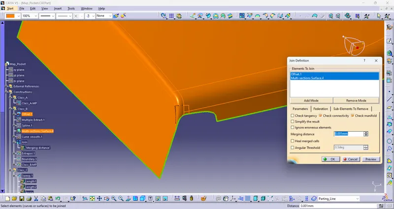
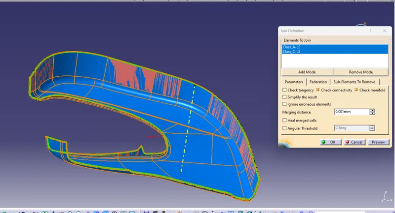
- Use Join command to add the surface the multi-section surface to the offset surfaec to form class B surafce.
Creating Class C surface
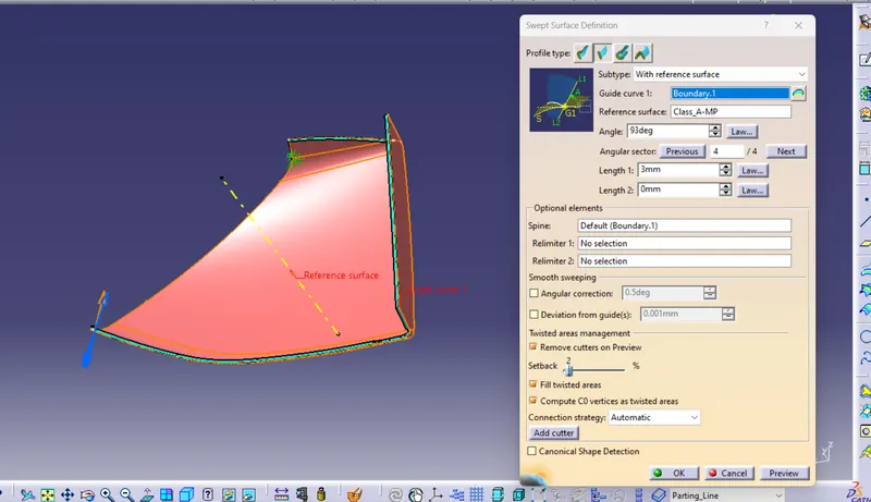
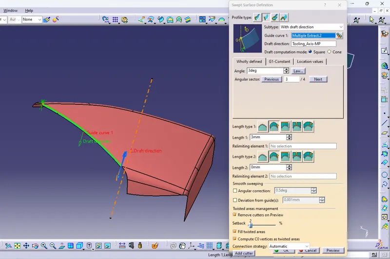
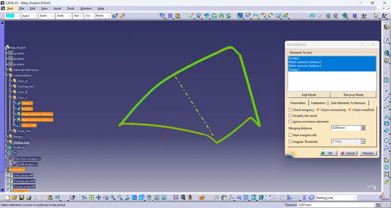
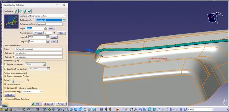
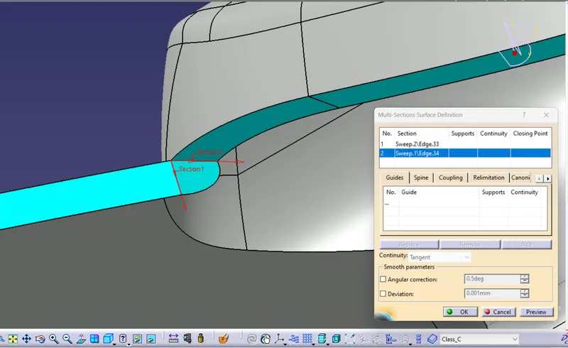
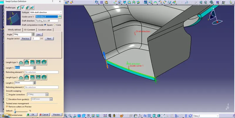
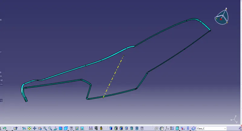
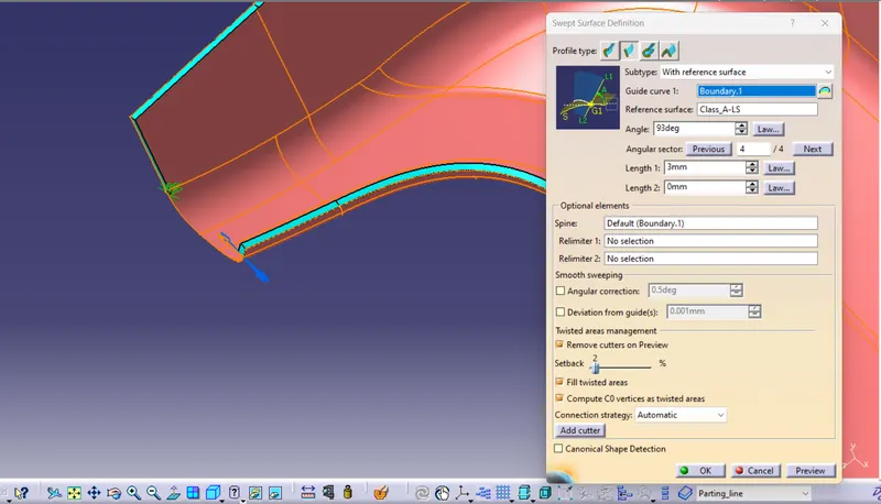
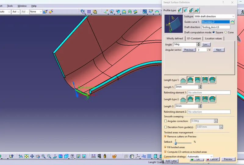
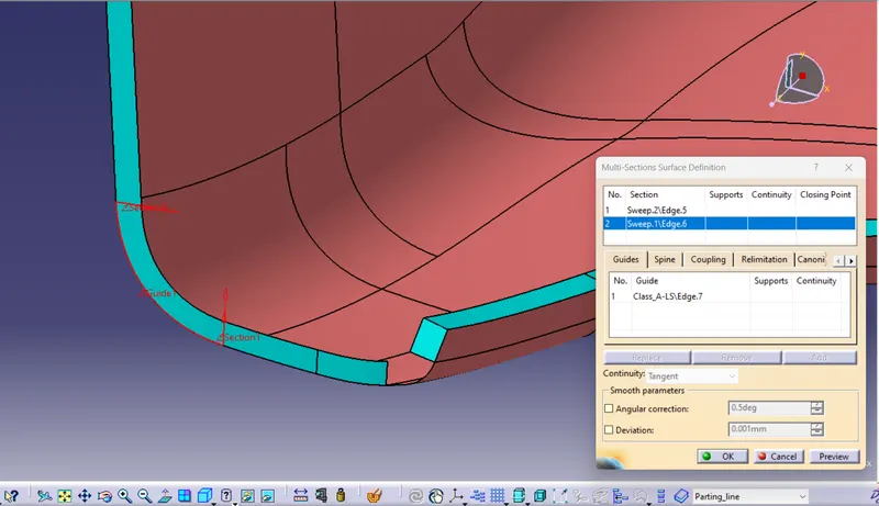
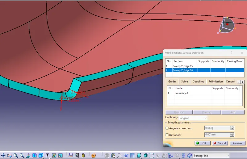
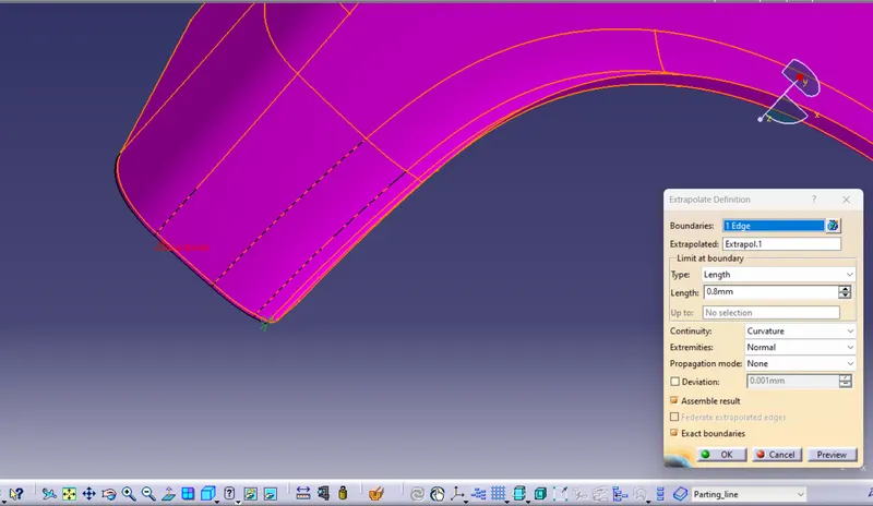
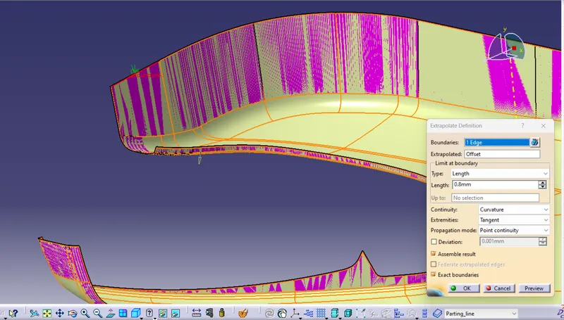
- By using sweep, multi-section surface, extraplotion command creating class C surface of Map Pocket.
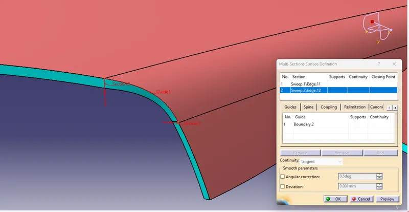
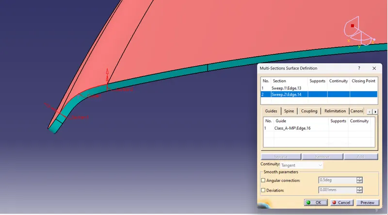
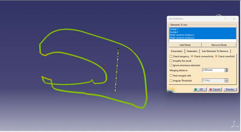
- Join all the created C Class surafce by using Join command.
Creation of Closed surface
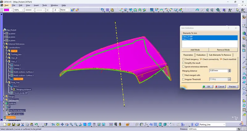
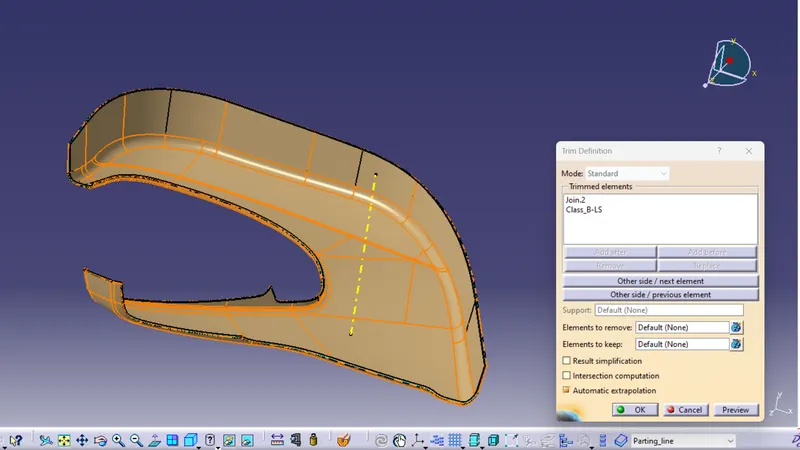
- Join the class A, B and C surface together to form a closed body.
- First use Join command to add class A and B surface.
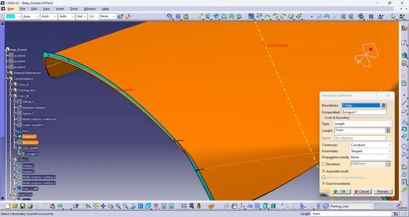
- Extrapolate the class B surface as per requirement to intersect with Class C surface to easily trim during the apply Trim command on them and form closed body.
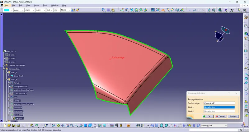
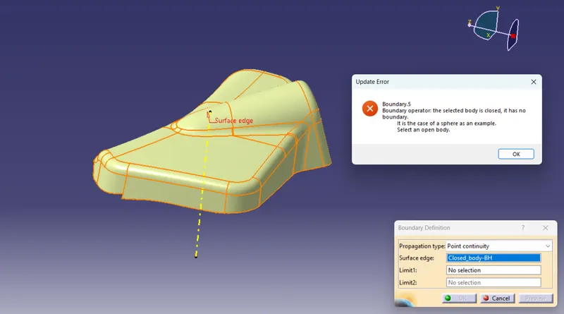
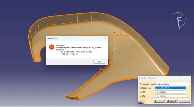
- Closed body of Map Pocket created now check the solid body by using Boundary command to ensure that the surface are fully closed no any gap or patch remain.
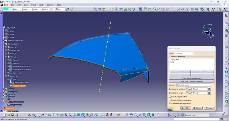
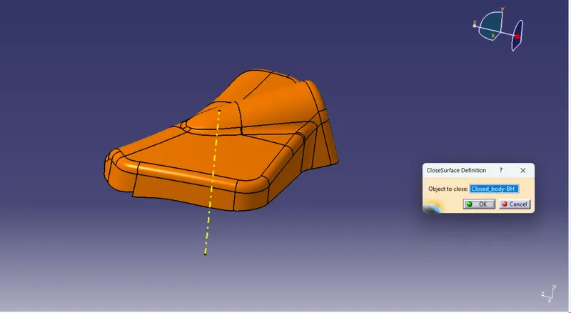
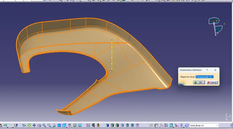
Now create the solid body of map pocket by using Closed surface command in solid workbench in seperate body.
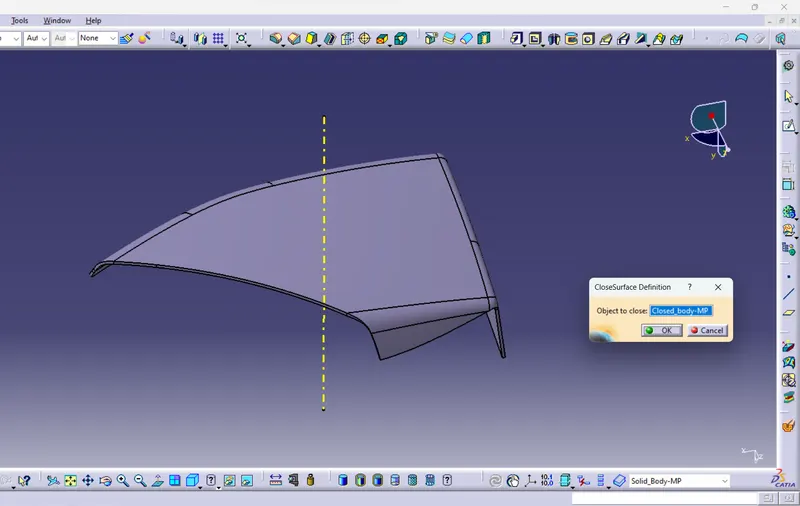
Now again check with Draft Analysis of the solid body.
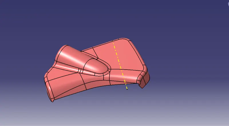
BOTTLE HOLDER
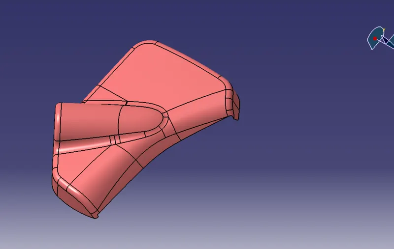
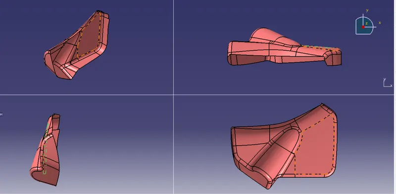
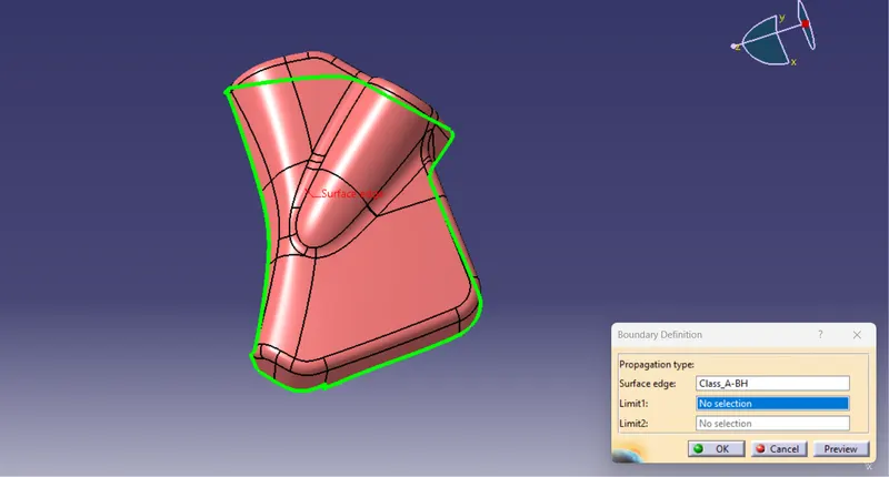
Class A surface
Creation of Tooling Axis
Draft analysis
Class B
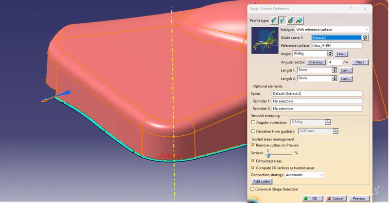
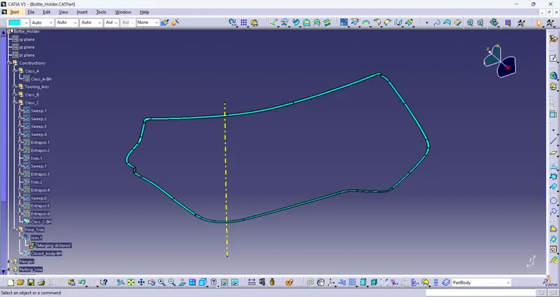
Class C
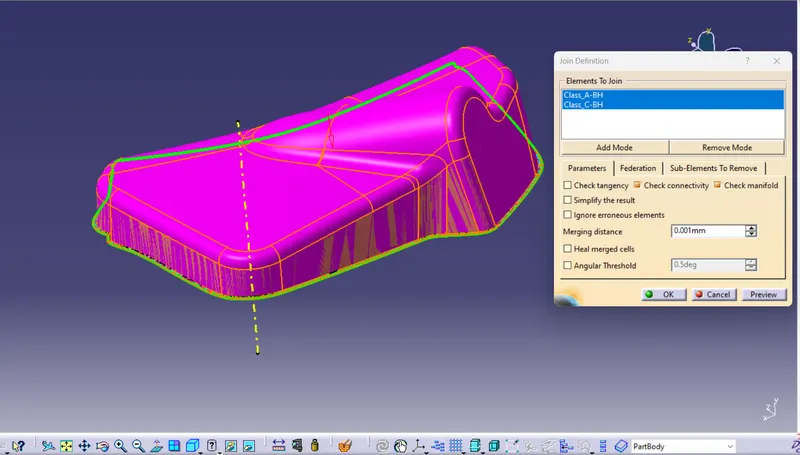
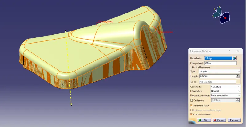
Closed body
Arm Rest
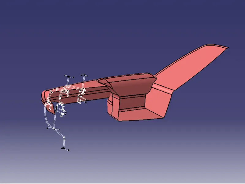
In the front of the car, a central armrest, which commonly folds away based on user preference, will also often include a storage compartment and sometimes even cup holders. Some also provide the location for controls for non-essential functions of the vehicle, such as climate control or window motors.
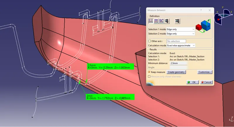
Master-Section of Arm Rest
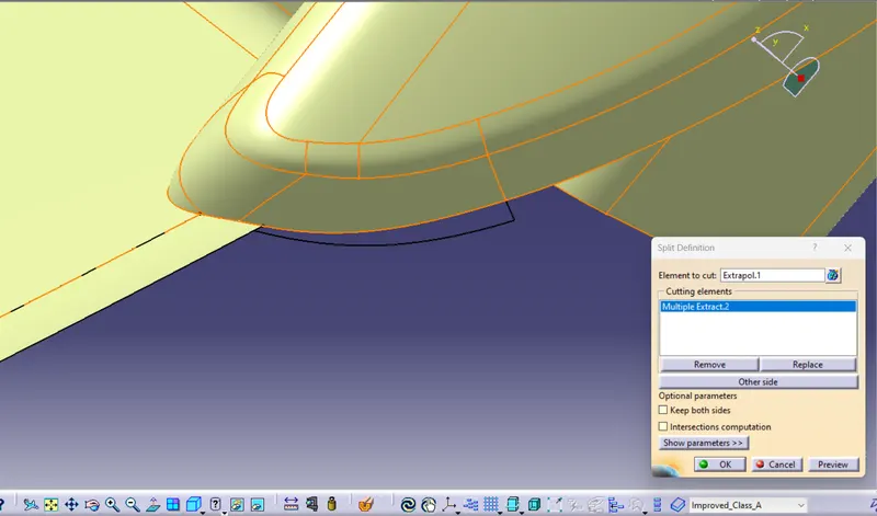
- Improving of Class A surafce
Checking the boundary countinuity of the tthe surface.
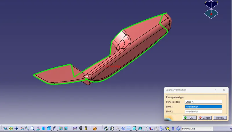
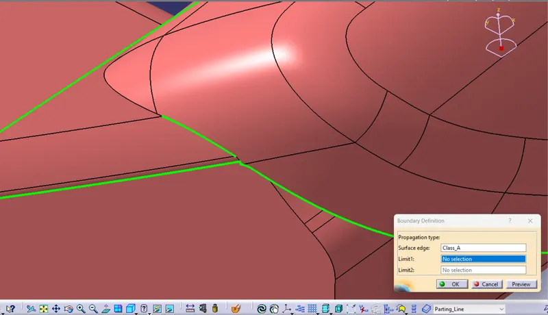
- their is a gap or patch between the surfaces in the styling surface of arm rest so I have to improved the surface to remove the patch.
- And their is also a sharp edge also which i have to remove to get smooth surface.
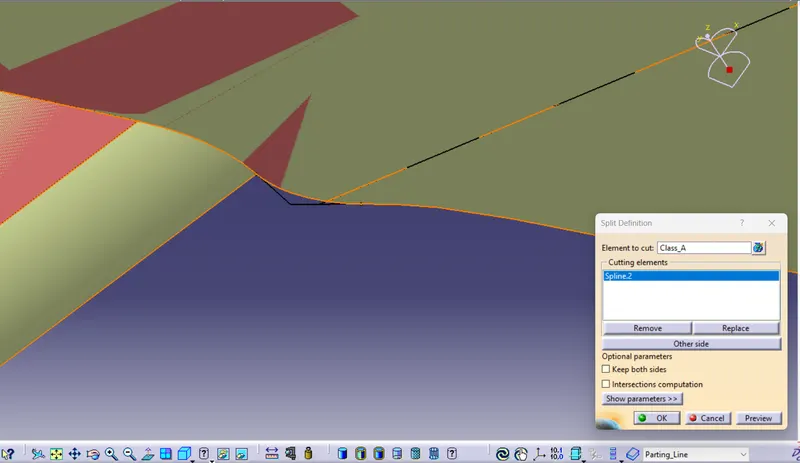
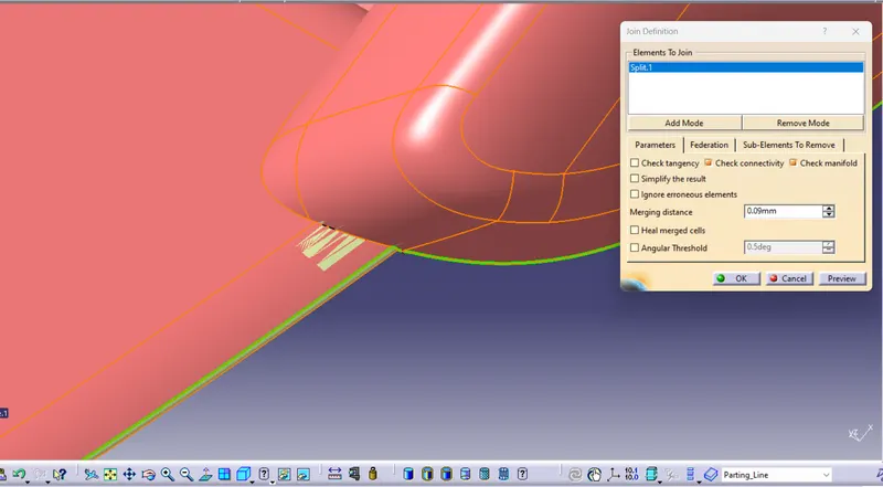
- first I remove the sharp egde by using spilt commanda nd thenby using join command increase the merging distance of the surface to .09 to get patchless surface.
- Now as per the mastersection give offset of 2 mm to get class A surface of the arm rest.
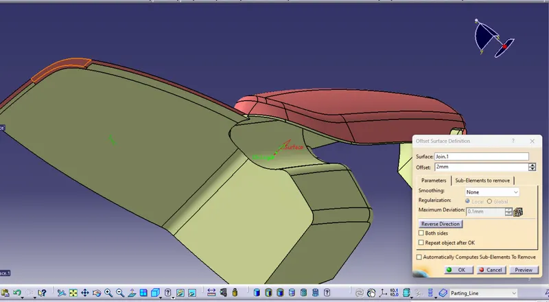
- After offset the surface, i get a some irregular surface at the edge of curvy surface.
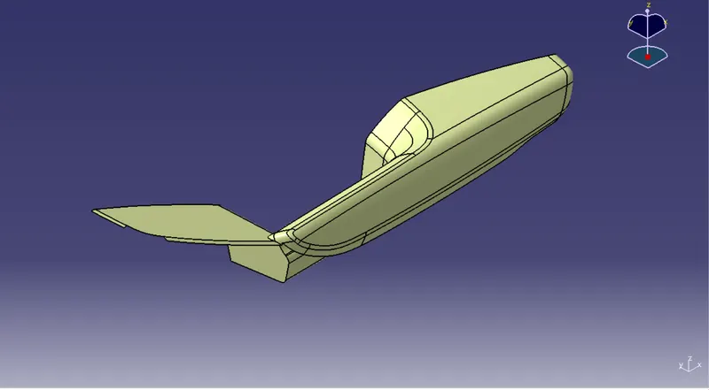
- So I have to first split the shape surface bu split command after creating the spline and line command.
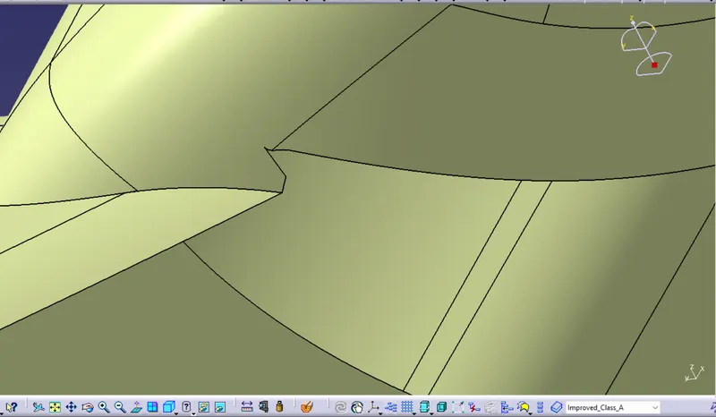
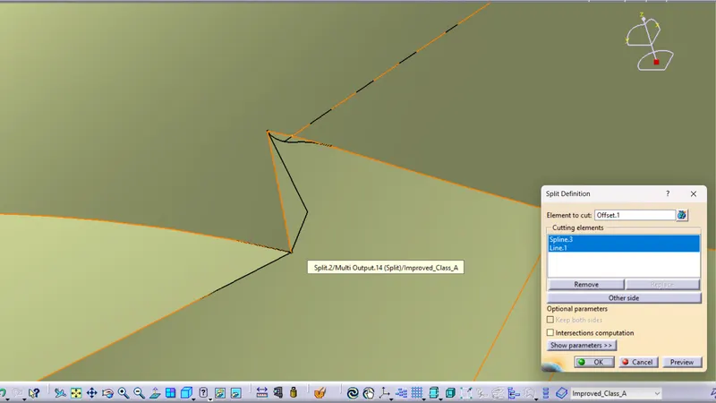
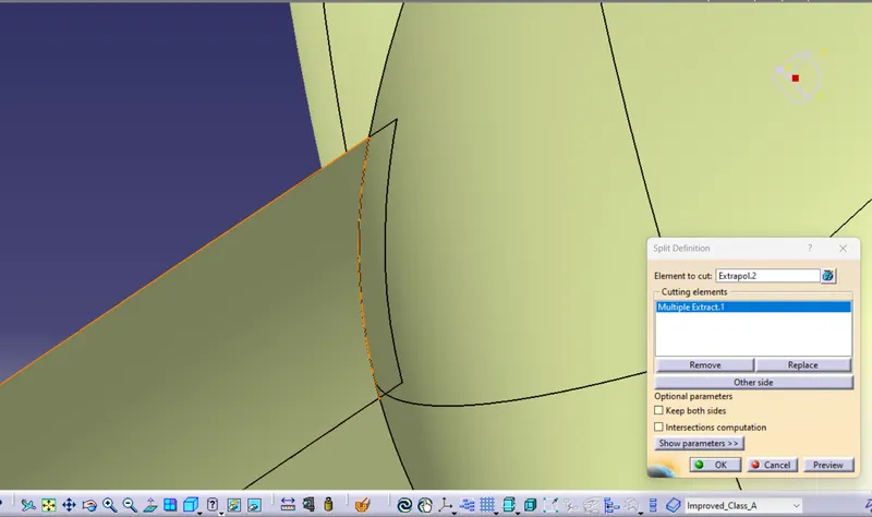
- Now I have to extraplote and trim the surface to the adjacent surface to get smooth surface along the adjacent surface. So first I have to remove the adjacent surface by using Remove sub-elements option in JOIN command and also take seperate extract of the surafce because I have trim the surface to get proper finishing of the surafce and for trim i have to required two separate surface.
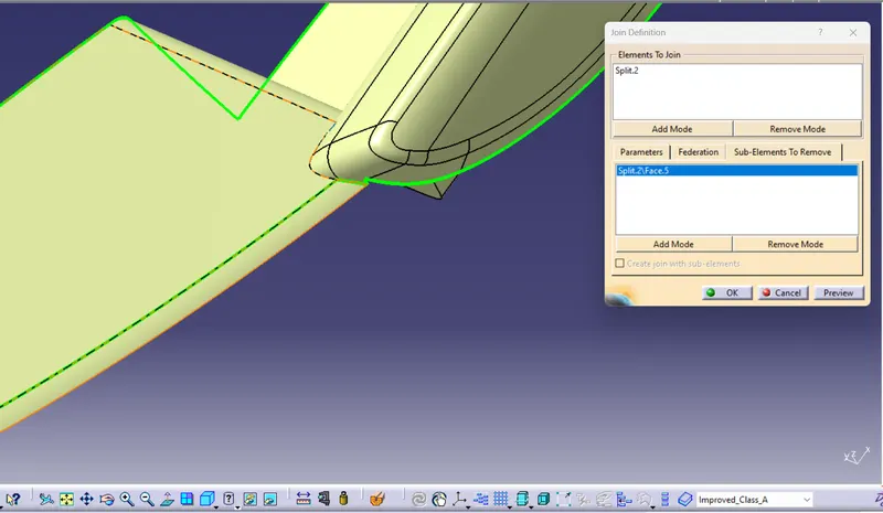
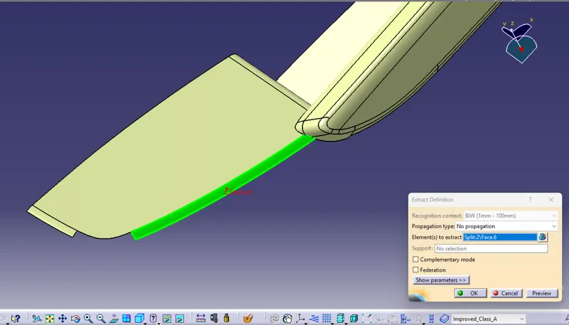
- Now i have to extraplote both the surface to get proper intersection to the adjacent surface.
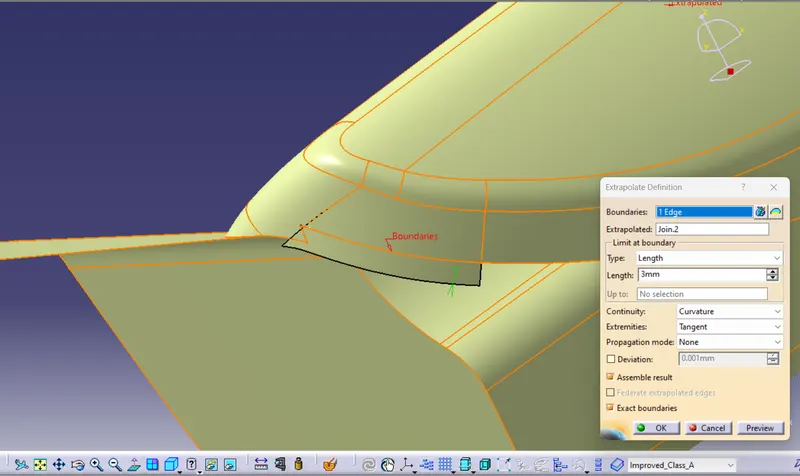
- then cut the surface to get smooth surface.
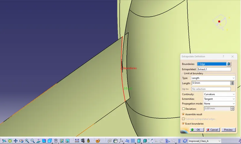
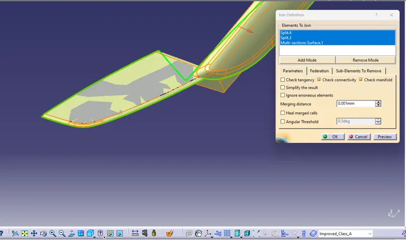
- For this I use spilt command to cut the both extract surface and then add the both surface by using Join commad.
- Class A surface
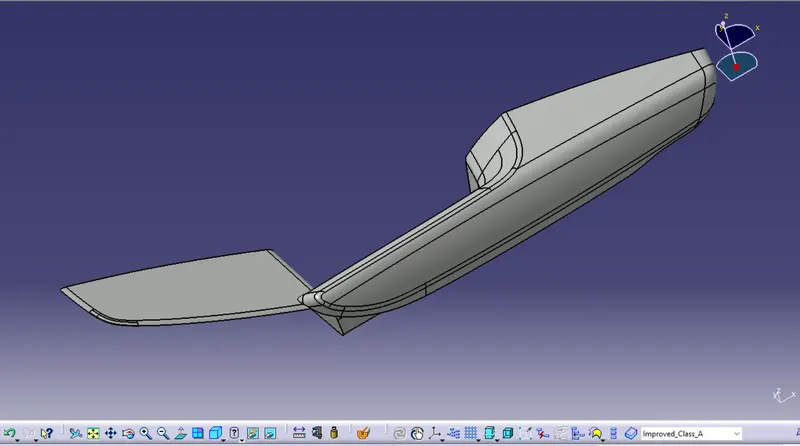
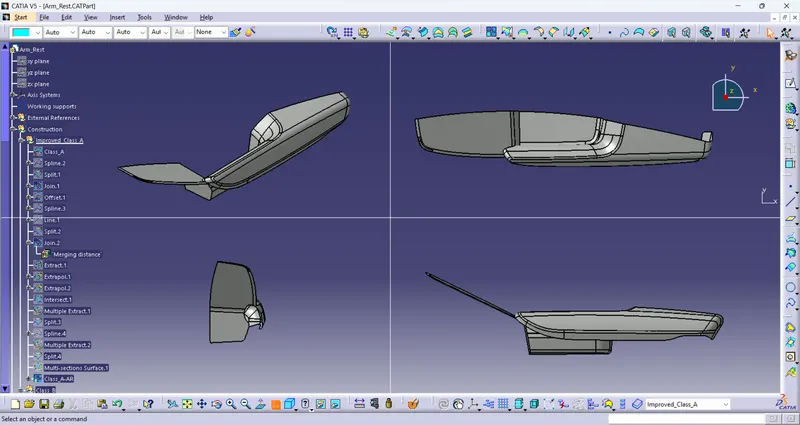
Creation of Class B
- Offset the class A surafce at 2.5mm to get class B surface as per mastersection.
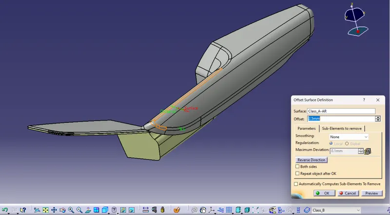
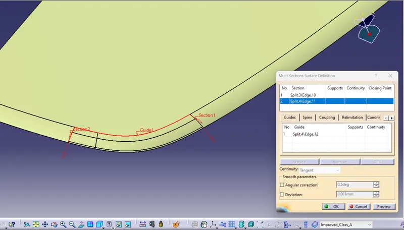
- There are some patches in the offseted surface so using surface creation command like multi-section surface, sweep, extraplotion command.
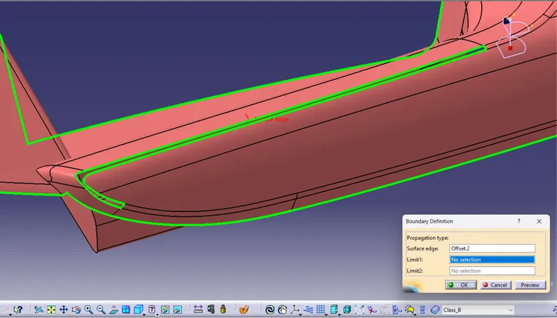
- here I extraplote the surface to match with the adjacent surface.
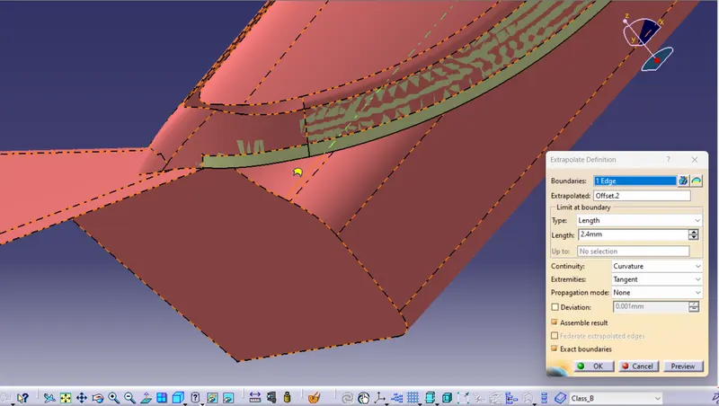
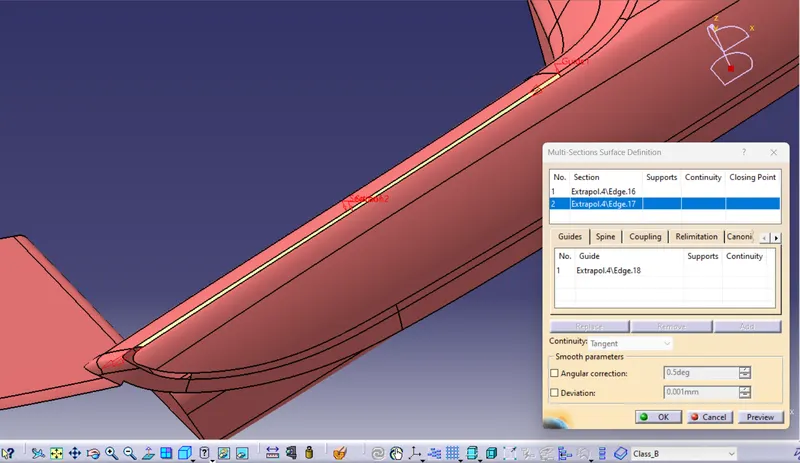
- Now by using multi-section command create surface of the patch and then join the surafce by using Join command.
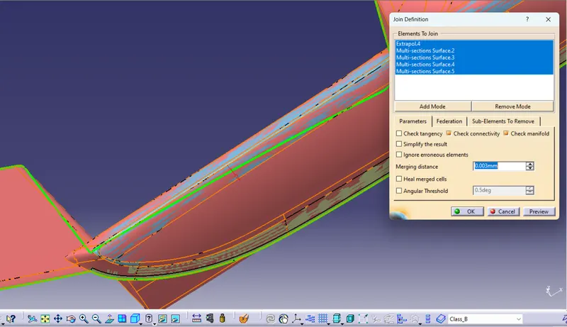
- Now join the surface to get Class B surface.
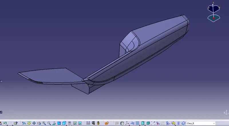
Creation of Class C

Creation of closed body
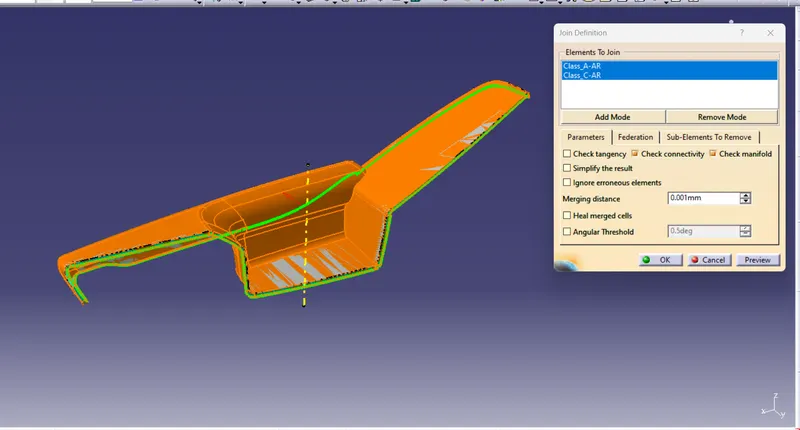
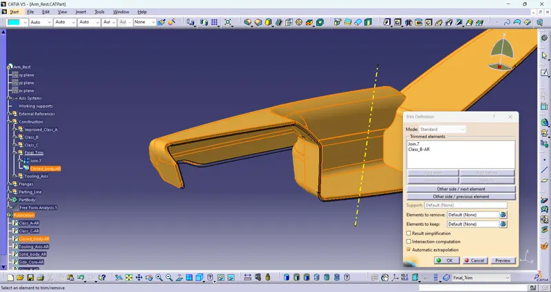
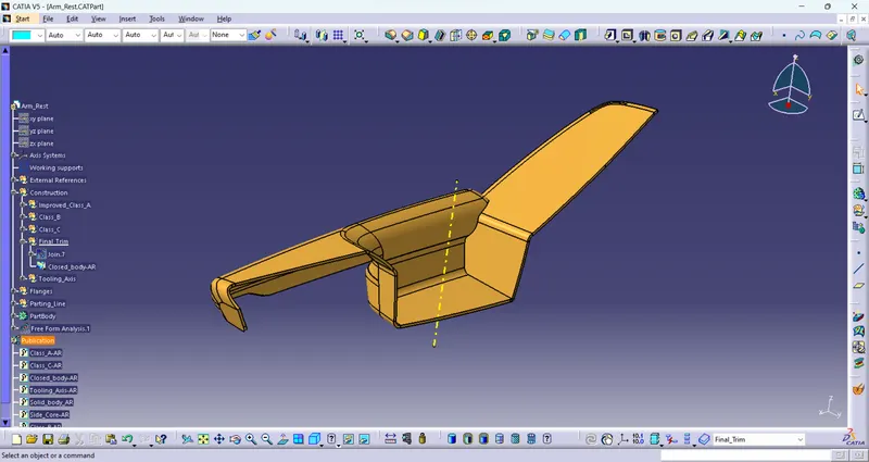
Closed Body
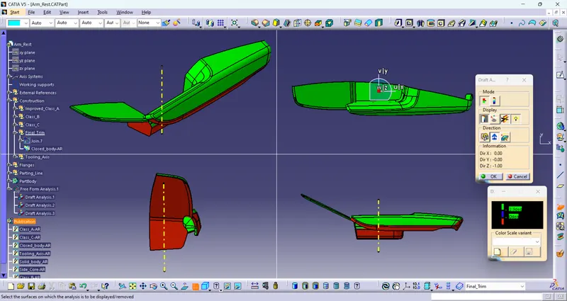
Draft analysis of Solid body
Lower Substract
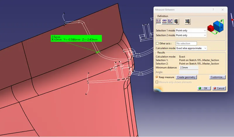
Master Section for Lower Substract
- Thickness of the part is 2.5mm as per mastersection.
Class A surface
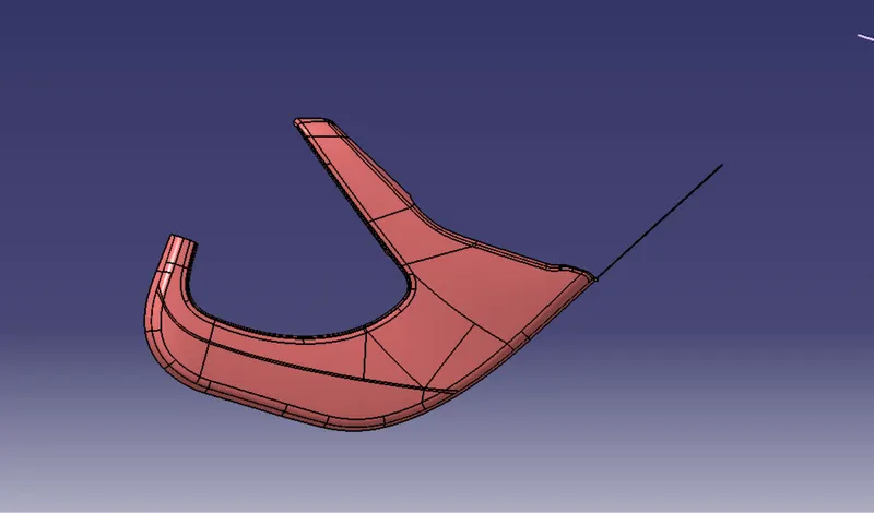
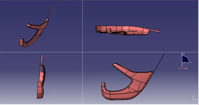
- Checking the surface by boundary defination command
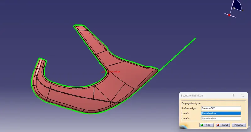
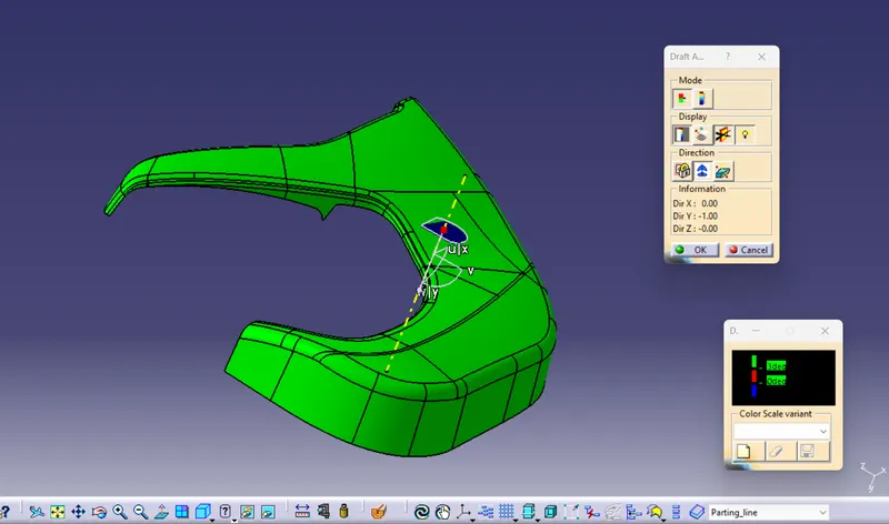
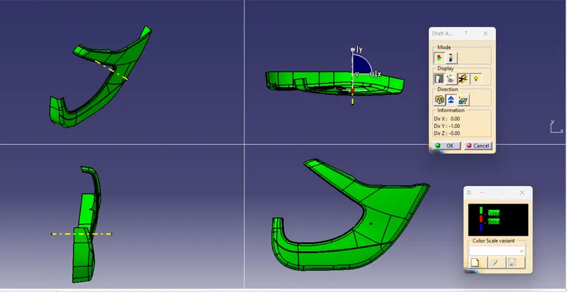
Creation of Tooling axis
Draft Analysis of Class A Surface
Creation of Class B
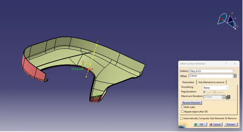
- Offsetting the Class A surface at 2.5 mm inner side to get Class B Surface
Creation of Class C
Creation of Closed surface
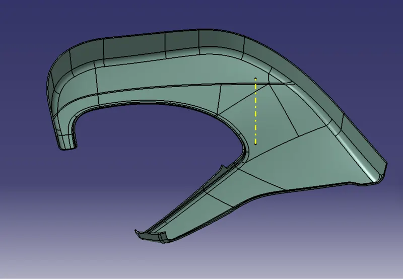
Soild Body
Draft Analysis of Solid Body
Creation of B-side features
- Heat stake
- Locators
- Dog House
- Flange
HEAT STAKE
Manufacturing operations currently use many different combinations of attachment methods to keep components together. Common fasteners such as bolts, screws, and rivets can be used to form permanent attachments, but there are attachment methods that don’t require secondary hardware. One of those methods is heat staking, which doesn’t require additional fasteners.
Heat staking can be done with a precise and rapid operation that also offers repeatable results every cycle. Manufacturing machine can be developed to complete multiple heat staking operations at once to decrease cycle time. The stakes don’t have to be parallel which makes the design options limitless.Heat staking is a great option that is comparable in strength and durability to other operations involving secondary fasteners without extra cost. These connections can also resist corrosion in harsh environments.
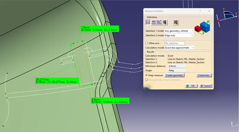
Master-Section of Heat stake
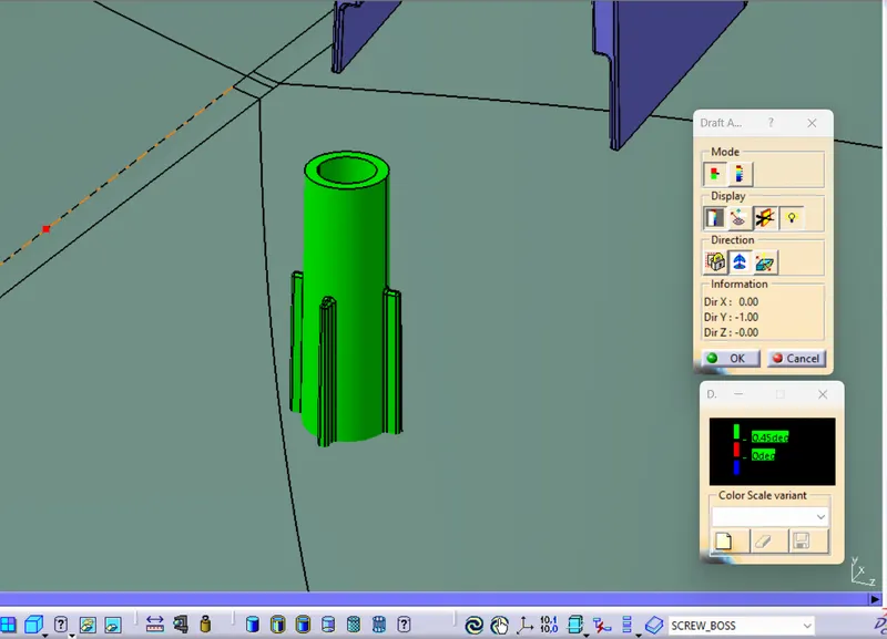
Draft Analysis of Heat stake
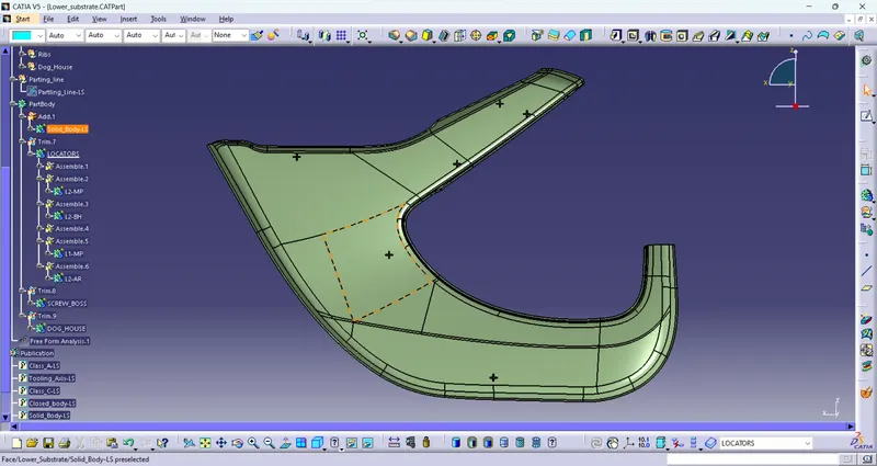
LOCATOR
Locators work as a 3 - 2 - 1 principle which is basically to fix a component to be machined or to be placed in an ideal position. There are a total of 12 degrees of freedom, 6 rotational and 6 translational.
Here locators are used to constraint the 11 DOF. There are 4-way and 2-way locators
Locator design Guidelines
- Thickness 1.3mm.
- Draft angle should be minimum 0.5degree
- Minimum fillet 0.25mm
- Height should be few length (in mm) more than others B-side features like heat stake.
- Atleast Two locators for each part.
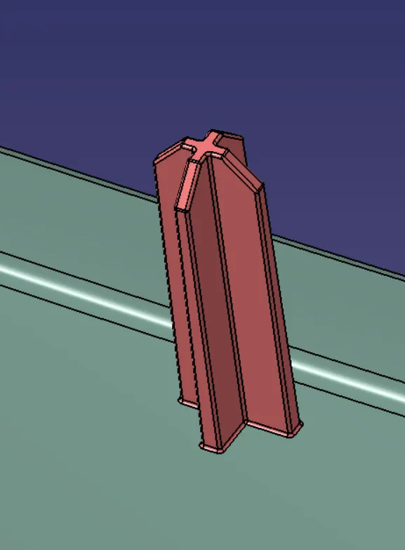
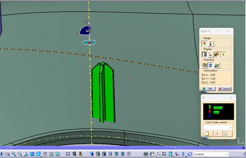
- Draft analysis of Locators along tooling axis (Y Axis) at .45mm
DOG HOUSE
Dog house is an engineering feature used in plastic trim design. Dog houses are used as supporting features. Sometimes other engineering features like snaps; locators etc. are mounted on them to increase their strength. Dog houses are subjected to draft analysis to prevent breakage of the component during ejection from mould cavity. Dog house and other engineering components are built on a B-surface.
Dog House Design:
Dog houses are used as supporting feature.Dog houses are subjected to draft analysis to prevent breakage of the component during ejection from mould cavity. Dog house and other engineering components are built on a B-surface.
Doghouse design Guidelines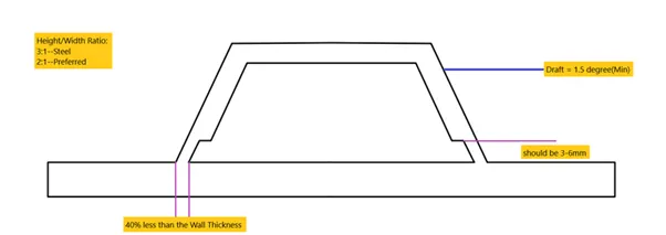
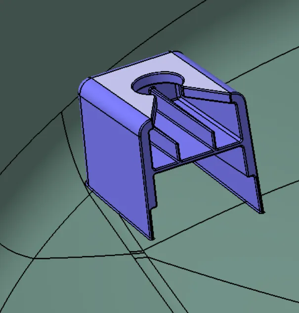
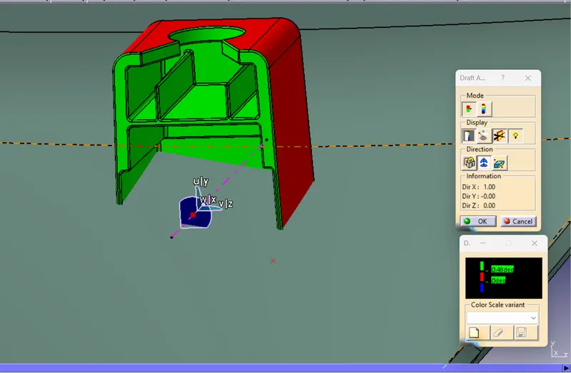
Draft Analysis of Dog House
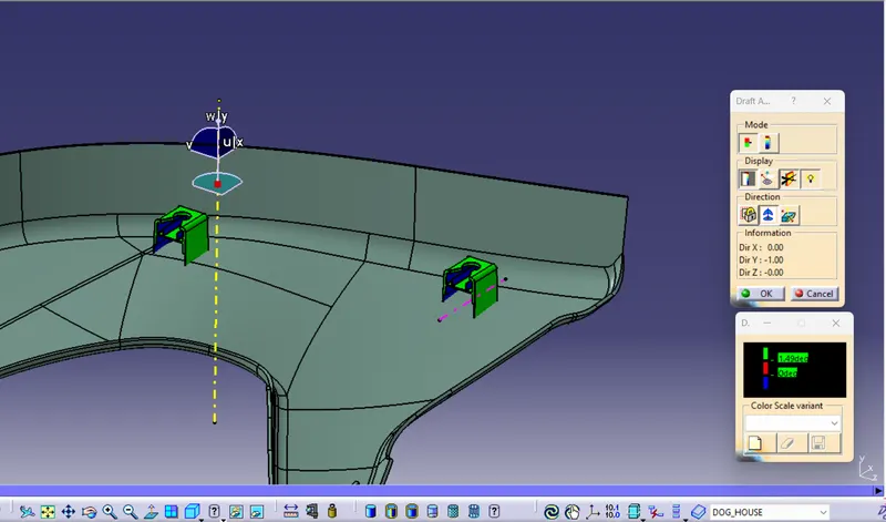
- Draft analysis of outer side of Dog House along tooling axis at 1.49 degree of draft angle
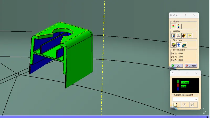
- Draft analysis of inner side of Dog House along Core axis at 0.48 degree of draft angle
Flange
To Join the part to part in heat staking process creation of flanges is required so plastic weld is to be done. For these, in one part creation of heat stake is required and creation of flanges is done another part so that joining together be done in plastic welding. For these draft angle of both heat stake and flanges should be same that means draft angle of B-side feature of parts which is to be join we take same draft angle. Thickness of flanges should be taken as master section or the main part thickness. 0.5 degree of draft angle is taken for the flanges.
Matersection of section
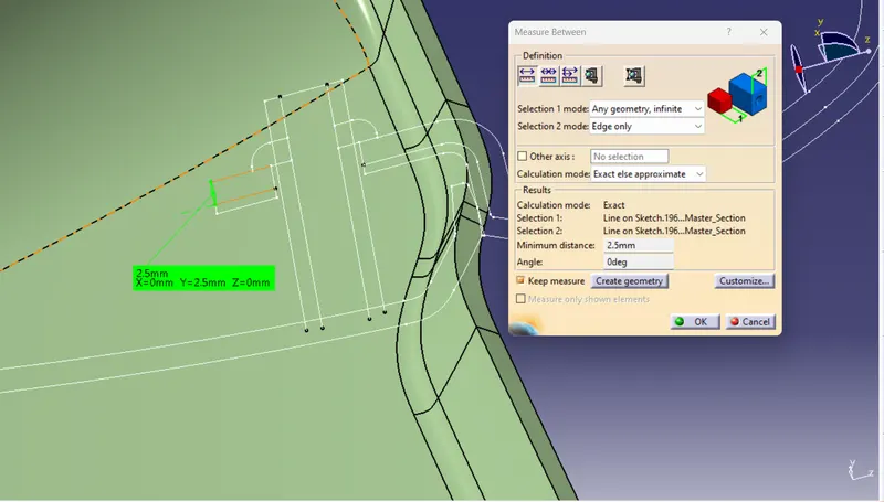
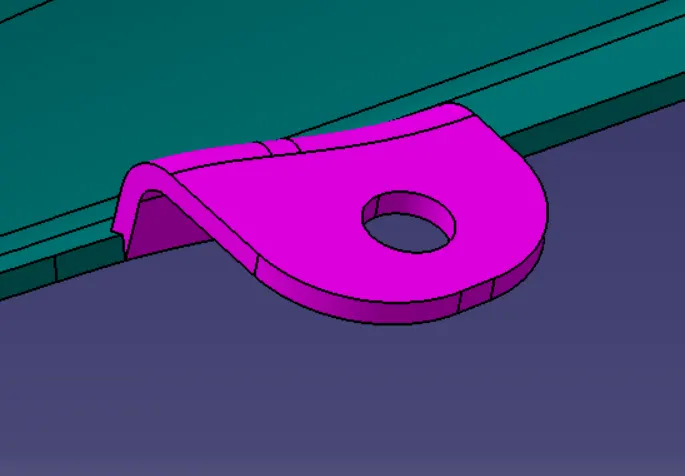
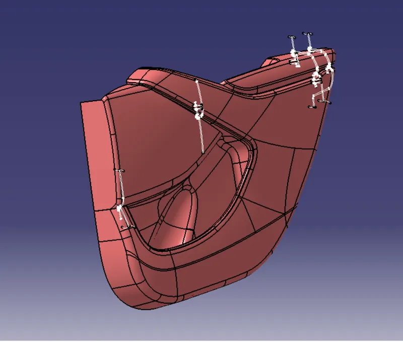
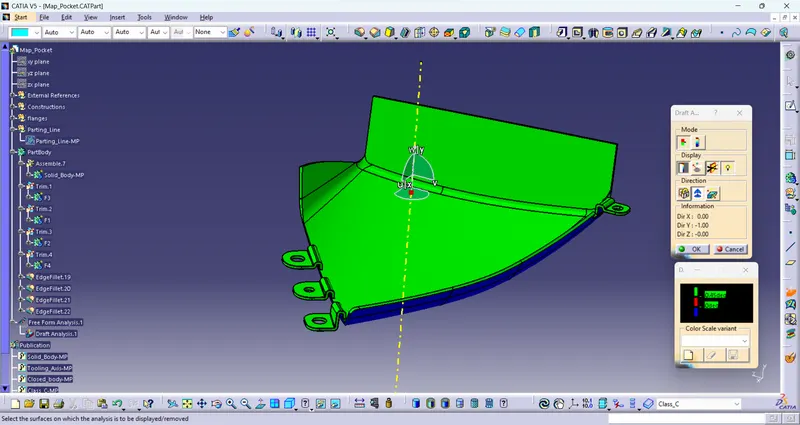
Map Pocket's Flange And its Draft analysis
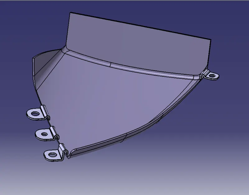
- Draft analysis of B-side surface i.e. flanges of Map Pocket along tooling axis (Y Axis) at 0.45 degee of draft angle
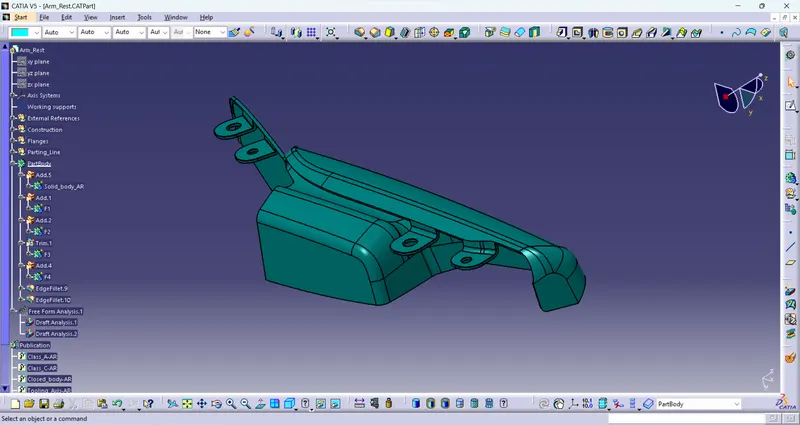
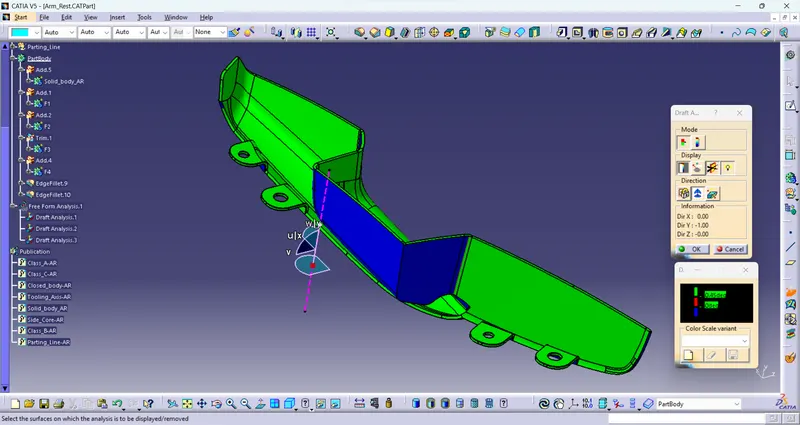
Arm Rest's Flange And its Draft analysis
- Draft analysis of B-side surface i.e. flanges of Arm Rest along core axis (Y Axis) at 0.45 degee of draft angle
Bottle Holder's Flange And its Draft analysis
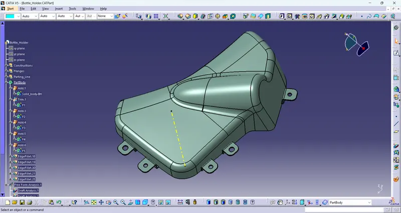
- Draft analysis of B-side surface i.e. flanges of Bottle Holder along tooling axis (Y Axis) at 0.45 degee of draft angle
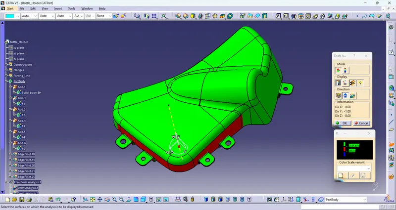
PARTING LINE
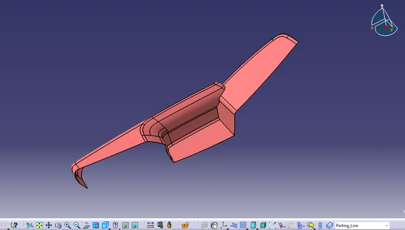
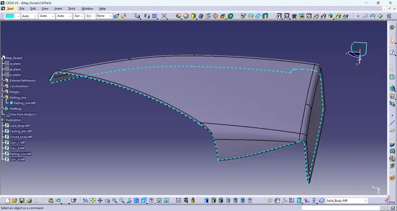
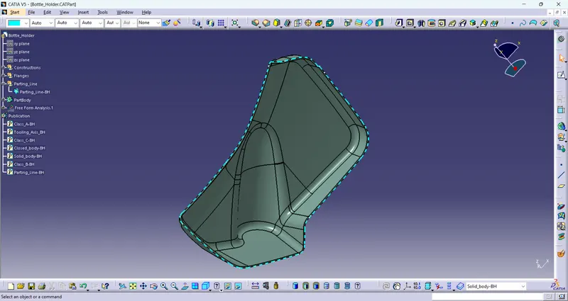
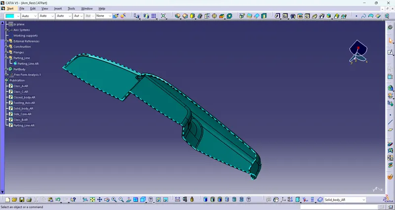
A parting line, in industrial casting of molds, is the border line in which draft angles change direction. One can check the parting line in the mould or product which divides the two half, i.e; the core and the cavity of a molded part. It is sometimes a starting point for the mold parting surface. Generally, take a parting line between the interaction of Class C and Class B to provide a better aesthetic look of the part from the class A surface side.
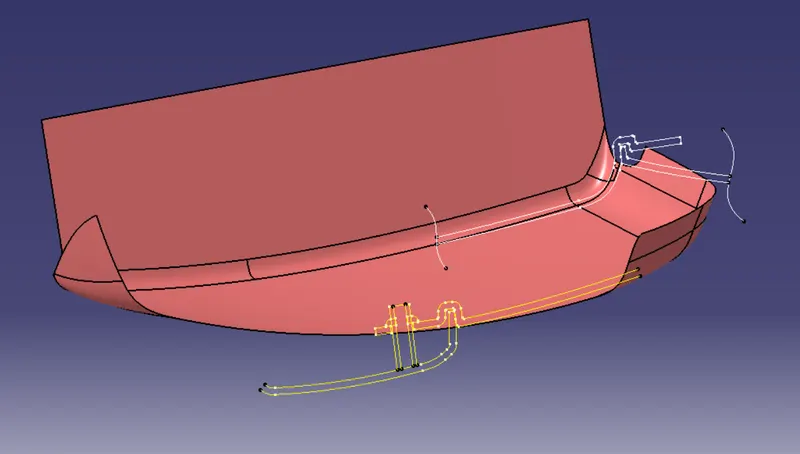
Parting line of Map Pocket
Parting line of Bottle holder
Parting line of Arm Rest
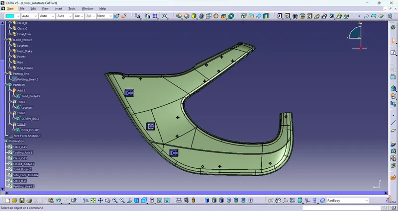
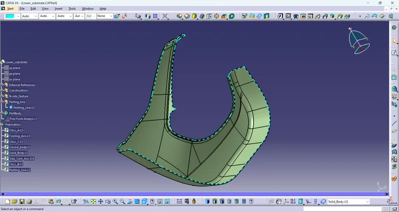
Parting line of Lower Substrate
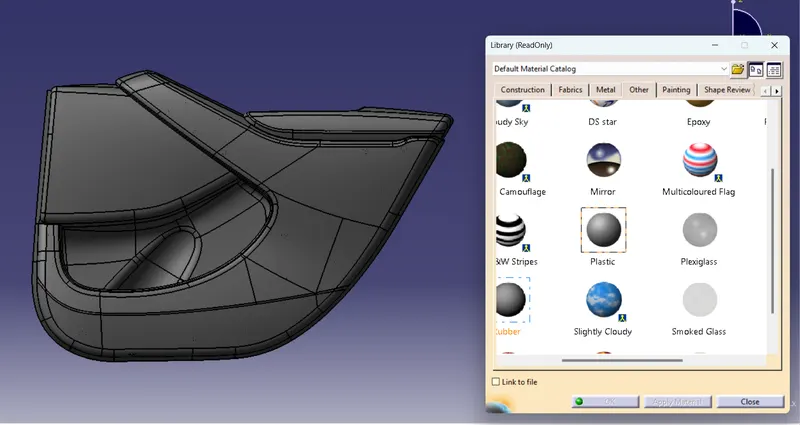
Material Selection of Door Trim
One of these type of plastic can be for door Trim as per requirements.
- Polycarbonate (PC)
- Polypropylene (PP)
- Polystyrene (PS)
- Acrylonitrile butadiene styrene (ABS)
Due to the unavailability of these plastics in Catia V5 so I used Plastic as a material for the door trim.
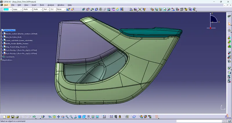
Final assemly of Door Trim
- Front View
- Back View
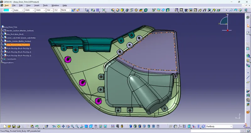
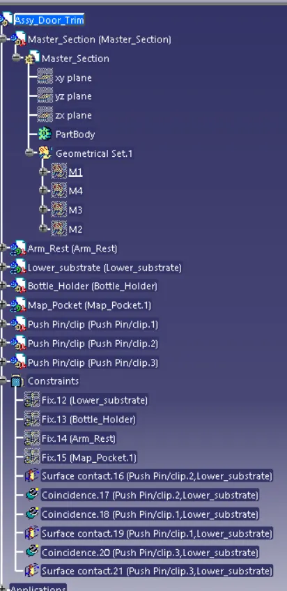
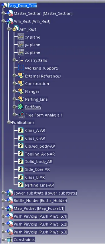
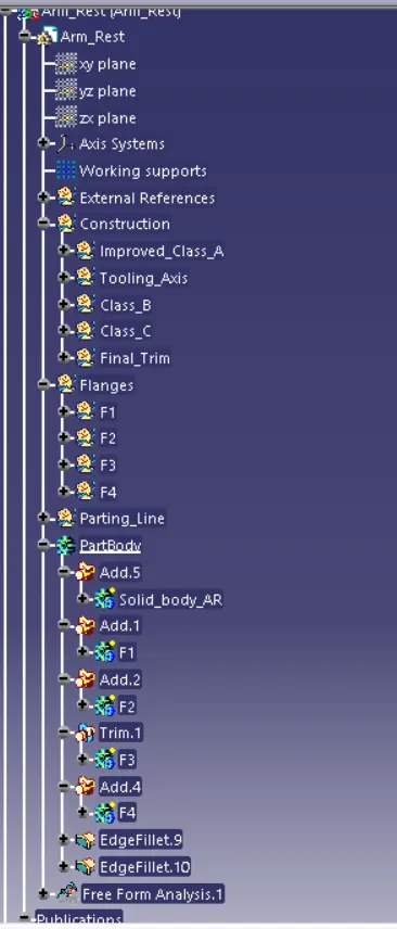
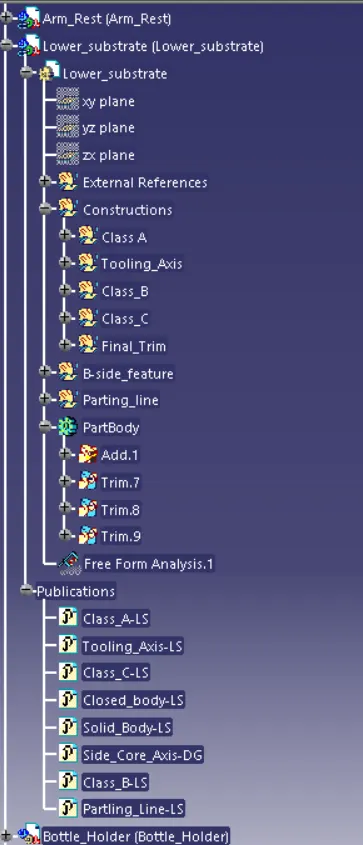
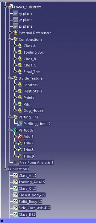
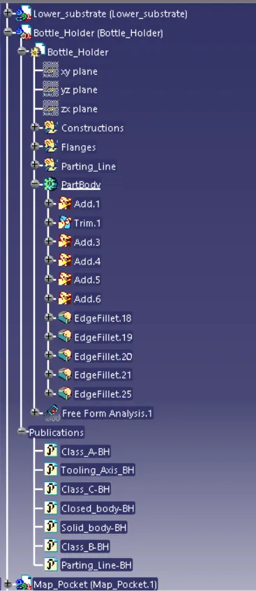
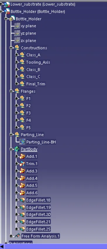
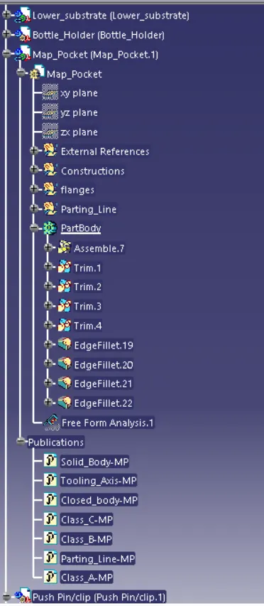
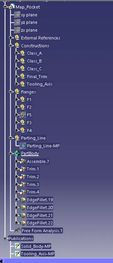
Screenshot of Working Tree