Week 9 - Project 1 - Door Trim Lower with Engineering Features
AIM Create the Door Trim Lower Plastic component through the given Class-A surface.
Create the Heat Stakes and the locators.
INPUT Given Class A surface and take the thickness of the components 2.5mm
Procedure for the projects
- Creating the tooling axis
- Draft analysis of Class A surface
- Creating Class B surface
- Creating Class C surface
- Surface and solid body
- Draft analysis of Solid body
- Engineering features Heat stakes and Locators
- Draft analysis of Solid body with engineering features
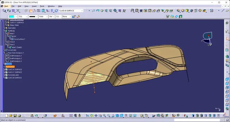
Tooling axis: Tooling axis is the direction at which core and cavity opens.
Procedure for creating tooling axis
- First check the connectivity of the given Class A surface by using the Boundary or Join feature to visualized and repaired the open edges of the surface.
- And then, analyse visually the best suitable plane or surface for tooling axis.
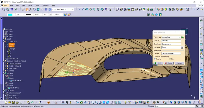
- After that, extract a surface from CLASS-A Surface and then create a centre point on the surafce for the axis on the point.
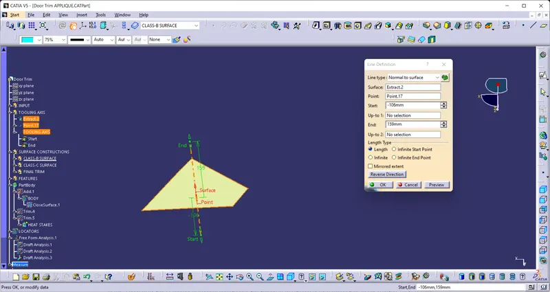
- then create a tooling axis from by using Normal surface line command on the extracted surface at the centre point.
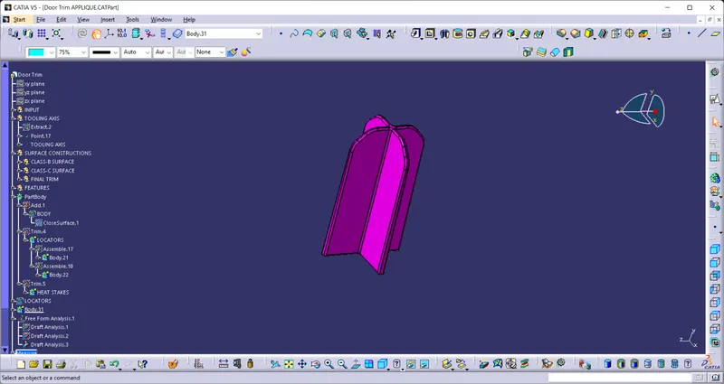
Locators
Locators work as a 3 - 2 - 1 principle which is basically to fix a component to be machined or to be placed in an ideal position. There are a total of 12 degrees of freedom, 6 rotational and 6 translational.
Here locators are used to constraint the any 11 DOF. There are 4-way and 2-way locators
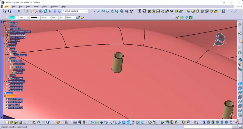
Heat staking
This is a fixing method of a plastic component to another dissimilar or similar surface or metal part. In this process, both of them are joined together by thermal welding. A Boss or a stud is made on the plastic part, which is then protruded onto the opposite part and reformed after the locators fix the part temporarily and then thermal welded on the boss.
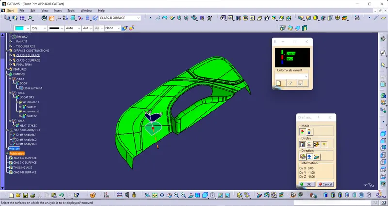
Draft Analysis
Darft analysis is a tool perform to check the product easliy removed from the core and cavity.
In this project we analysis the draft angle of the Class A Surface And the plastic components with feature.
Screenshots of the Draft analysis report for the given Class-A surface
Screenshots of the Draft analysis report for the given final plastic component with heat stakes and locators
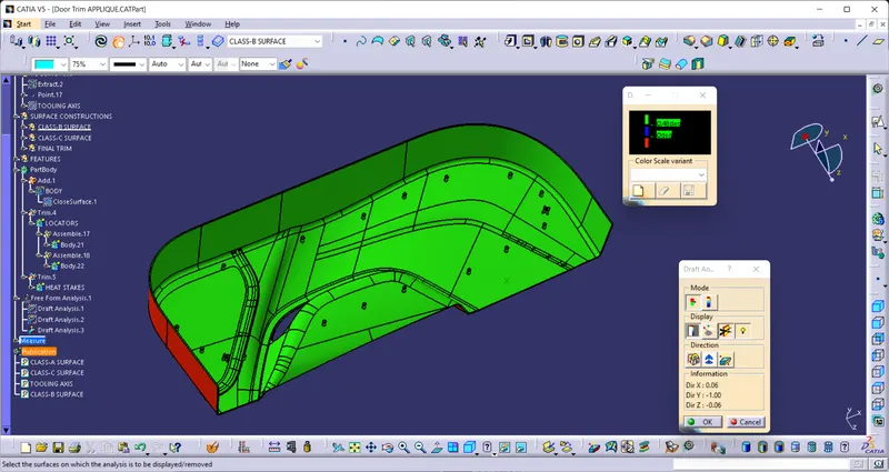
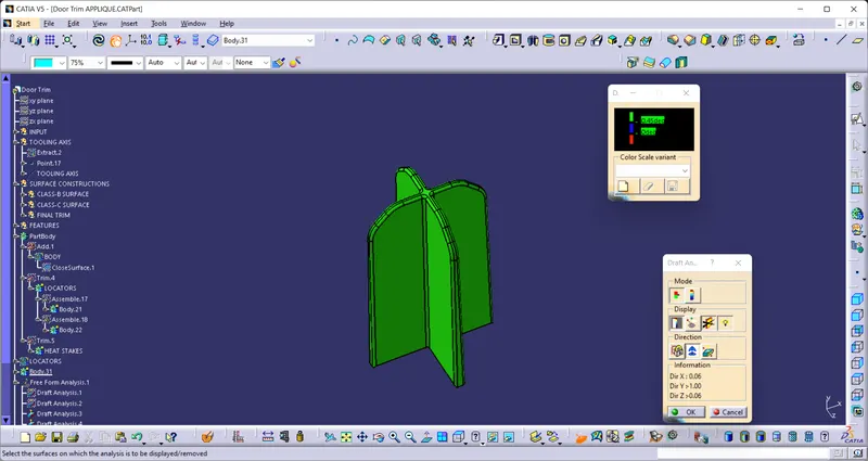
Screenshots of the Draft analysis report of the locator
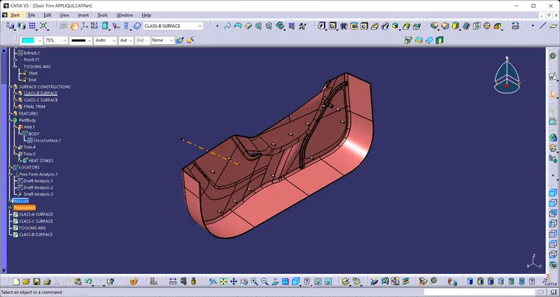
Screenshots of the completed design in various orientations
- Isometric View
- Front View
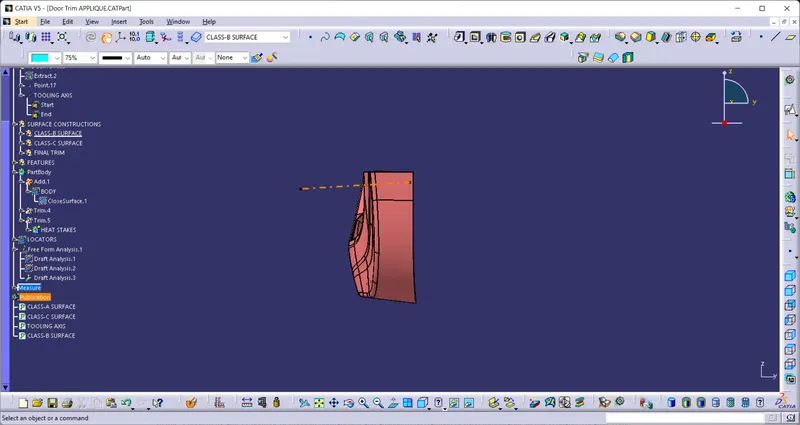
- Side View
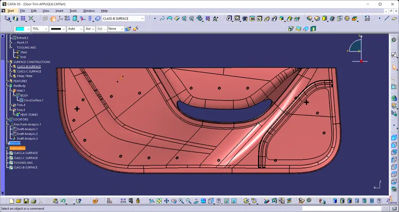
- Top View
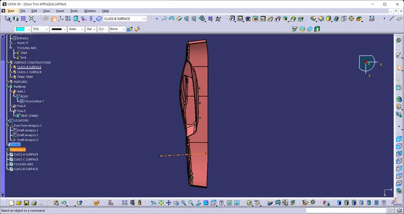
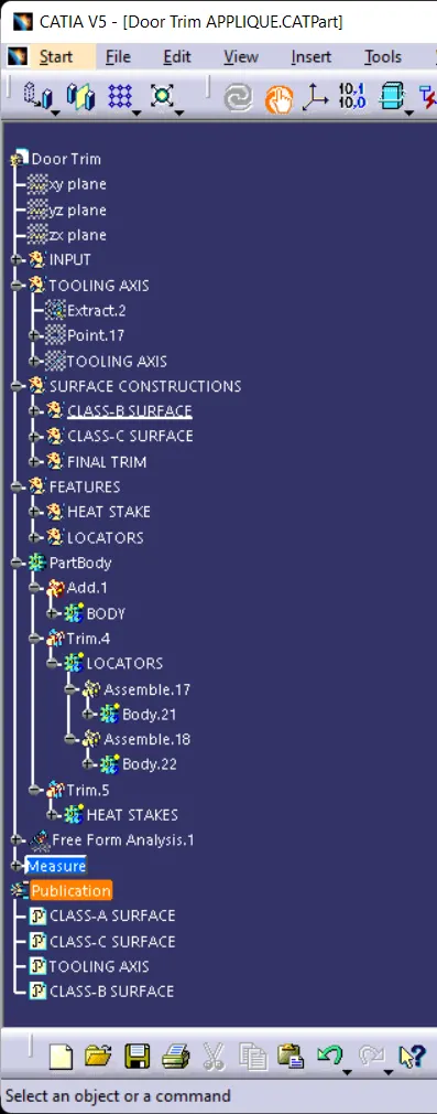
Tree structure of Door trim lower