Design of Shallow Foundation (Isolated Footings)
PROJECT:- Design of Shallow Foundation (Isolated Footings)
AIM:- Design a square footing of column size 400x400mm
INTRODUCTION:
The spread footing behaves like an inverted cantilever with loads applied in the upward direc-tion. As a rule, a spread footing is a quite rigid element therefore, the applied soil stresses are almost linear and in case of a symmetric (with respect to the pedestal) footing, they are or-thogonal. These soil pressures constitutes the loads carried by the footing which behaves like a slab and is deformed.Soil pressures and deformation of an isolated spread footing.
- Footings and other foundation units transfer loads from the structure to the soil or rock supporting the structure.
- The distribution of soil pressure under a footing is a function of the type of soil and the relative rigidity of the soil and the foundation pad.
The most common type of footings used are;
- Strip or wall footing
- Spread footing
- Stepped footing
- Tapered footing
- Pile cap
- Combined footing
- Mat or raft footing
QUESTION:-
Design a square footing for a column size of 400x400. The compression axial load for the load combination of (1.5 DL + 1.5 LL) is 2000 KN. The safe soil bearing capacity is 150 KN/m2 at a depth of 2 metres below E.G.L. Participants are free to go for either a tapered or stepped footing. Besides the total axial load, also account for the self-weight of the footing and soil above it. Assume M25 concrete grade. Do the following checks:
- If the gross bearing pressure under the footing is within safe bearing capacity
- Provide sufficient depth and longitudinal steel for resisting bending and shear
- Sufficient anchorage for column steel into the footing
- If the bearing pressure at column-footing joint is within 0.45 times the maximum concrete compressive strength
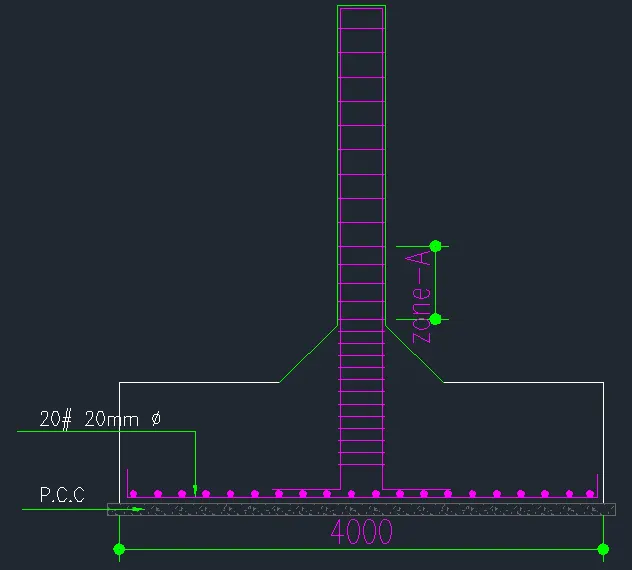
Provide a simple sketch showing the size of the footing, maximum and minimum depth of the section, flexural reinforcement in both directions and anchorage of column steel.
Please do go through the solved examples in the document provided with the challenge.
PROCEDURE:
GIVEN:-
- Column Size = 400mm * 400mm
- Compression axial load = 2000 KN
- Safe soil bearing capacity = 150 `(KN)/m^2`
- Compressive Strength`f_(ck)= M25`
- depth = 2 metres below E.G.L
- Soil depth = 20 `(KN)/m^3`
- RCC density = 25 `(KN)/m^3`
Steps involved in Design of Footing:-
- Determine the size of footing
- Upward pressure
- Depth of footing on the basis of B.M
- Area of reinforcement
- Check for one way shear
- Check for two-way shear
SIZE OF FOOTING:-
Assume self-weight of footing equal to 105 of superimposed load.
`W_d =10% of 2000`
`= 0.1*2000 = 200 KN.`
Now, Total load,
`W = W_L + W_d`
`= 200 + 200`
`W = 2200 KN.`
Now, Area of footing ;
`A = W / (SBC)`
`= 2200 / 150 = 14.67 m³`
Now, let us take,
`B = √A A = √14.67= 3.82`
Hence, we provide the size of square footing is, `= 4m * 4m`
Therefore, Area of footing is `16 m².`
NET UPWARD PRESSURE `(ρo)`:-
`ρo = (W*15) / ( size of fo oti ng )`
`ρo = (2200*1.5) / (16)`
`ρo = 206.25 (KN)/m^³`
DEPTH OF FOOTING ON THE BASIS OF B.M:-
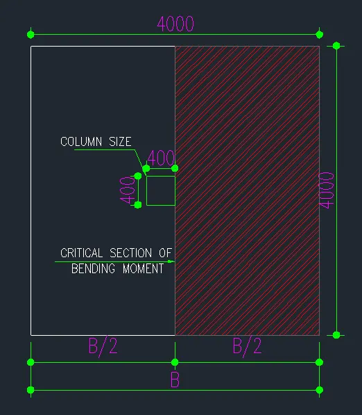
The minimum B.M at the face of column and is given by,
`M = ρ*(B)/8(B-b)^²`
`= 206.25*(4)/8(4-0.4)^2`
`= 1336.5 (KN)/m`
Now, Ultimate moment
`M_u = 1.5 (M)`
`= 1.5*1336.5`
`M_u = 2004.75`
To get the ultimate moment we have calculated that,
`M_u = 1.5 *FOS * Moment.`
Now, Depth of footing (D),
`M_u = 0.138 f_(ck) Bd^2`
`2004.75 = 0.138 * 25 * 4000 * d^2`
`d^2 = (2004.75 * 10^6) / (0.138* 25 *4000)`
`d^2 = 145271.73`
`d = √145271.73`
`d = 381.14`
By the thumb rule, we take 2.5 times higher value of for shear check.
`d = 381.14 * 2.5 = 952.85`
`D = d+50`
`D = 952.85+50`
`D =1003 mm`
AREA OF REINFORCEMENT:-
`Ast = 0.5 f_(ck) / f(y) [ 1- √ 1 − (4.6 M _u)/ (f_(ck) B d ² )] B_d`
`= 0.5*25 / 415 [ 1- √ 1 − ((4.6 * 2004.75 * 10^6) /(f_(c k) B d ² ))] *4000*953`
`A_(st) = 5985.3 mm^2`
Now, we have to find the % of the reinforcement
`P = (A_(st))/(B_d)* 100`
`P = 5985.3/(4000*953) 100`
`P = 0.157 %`
No of bars required for the reinforcement, we assume that 20mm dia bars,
`A_(st) = 5985.3 mm^2`
`π/4 20^2 = 314.5`
No:of bars `= 5985.3/314.5 = 20` bars.
Therefore, Spacing b/w the bars
`= B/(No . ofBars)`
`= 4000/20`
`= 200 mm c/c`
CHECK FOR ONE WAY SHEAR:-
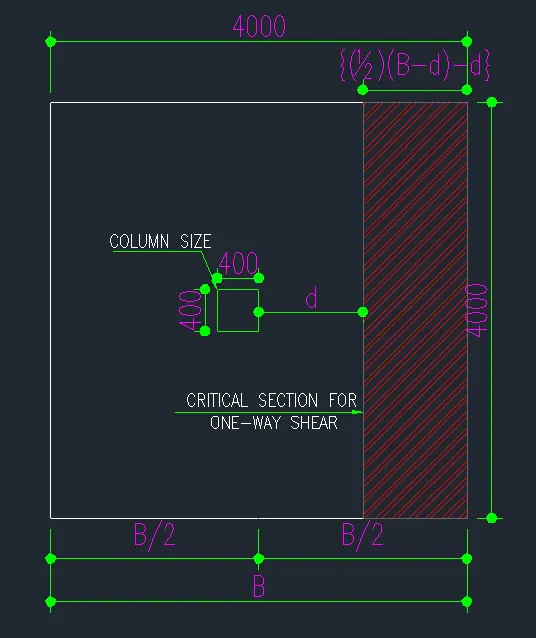
For, One-way shear, critical section is located at a distance ‘d’ from the face of the column.
Now, shear force `V = ρo*B {1/2(B-b)-d}`
`= 206.25 * 4 {1/2(4-0.4) – 0.952}`
`= 699.6 KN`
Ultimate shear force `V_u = 1.5*V`
`= 1.5*699.6 = 1049.4 KN`
Nominal shear stress `= (V_u)/(B_d)`as per IS 456-2000
`=(1049.4*10³)/(4000*952) = 0.27 N/(mm^2`
Now, design shear strength of concrete ττc
`τ_c = τ_c *K`
`K=1`, because depth > mm
`τ_c=0.28 N/(mm²`
Then,`τ_v < τ_c`................Hence OK.
Now,`τ_v < τ_c`
`(V_u )/B_d = K*τ_c`
`d=V_u / (B*K*τ_c`
`d=(1049.4*10)/(4000*1*0.28)`
`d=937 mm`
d provided `= 953 > 937 mm`
Therefore, OK for One-way shear.
CHECK FOR TWO WAY SHEAR:-
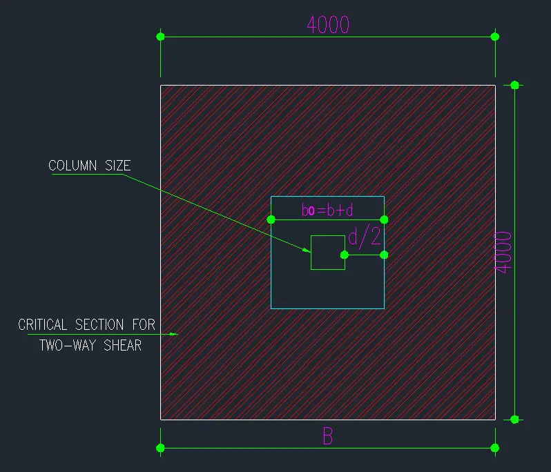
For, two-way shear, critical section is located at a distance ‘d/2’ from the face of the column all around.
The width `b_o = b+d = 400+953 = 1353 mm`
Now the Net shear force acting in the perimeter.
`F = ρo [ B² - b_o^2]`
`= ρo [B² - (b+d)²]`
`= 206.25 [4 –(1.35)²]`
`= 449.10 KN`
Now ultimate shear force, `F_u = 1.5 * F`
`= 1.5 * 449.10 = 673.65 KN`
Now, from IS 456-2000
`τ_v= F_u/(4bd)= = 0.13 N/(mm²`
Now, permissible shear stress`(k_s τ_c)`
Where,`K_s =1`
`τ_c = 0.25 √f_(ck)= 0.25 √25 = 1.25`
`k_s *τ_c = 1*1.25 = 1.25`
Therefore, `τ_v < τ_c` .........Hence, safe in the two-way shear
RESULT:-
Hence the given 400*400 footing has been designed successfully.