Creating various 3D Models like Furniture, Footing, Girder, Column drop with panel and Gable Wall in AutoCad
AIM:-Creating various 3D Models like Furniture, Footing, Girder, Column drop with panel and Gable Wall
INTRODUCTION:-
In this asignment we use various basics commands in Autocad 3d such as Sweep,3dorbit,Region,Boundary,3drotate,Loft,Cone,Polysolid etc. with the help of these tool or commands we are able to do some precision drafting and 3d visualised work in autocad .
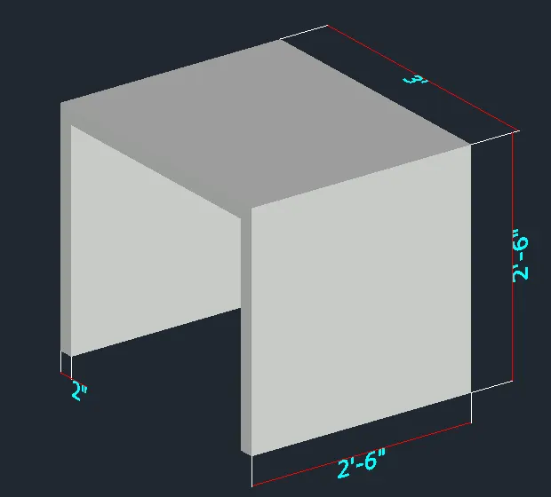
1. Create a 3D Furniture element as shown in the Figure. Assume dimensions which are missing.
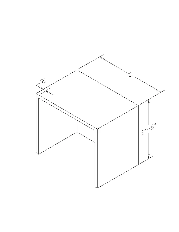
Commands used:
- Extrude
- Offset.
- UCS.
- Box.
- Union.
- Subtract.
- Move.
- 3d orbit.
- Loft.
- Sweep.
- Cone.
- Region.
- Boundary.
PROCEDURE:-
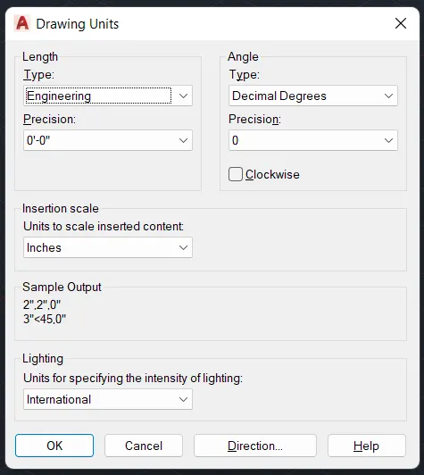
- Type UN and set the units as Engineering and precision as 0' 0"
- Set the units as Inches in the insertion scale
- Type Limits in the command box and set the Lower limit as 0,0 and Upper limit as 100',100'
- Type Z enter for Zoom Enter and A Enter for Zoom all
- In the Top right corner, Select the UCS icon and convert the space into a 3D view
- Select the Rectangle tool by typing REC or Rectangle in the command box
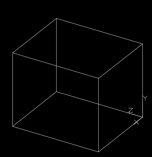
- Draw a rectangle with a dimension of length 2'6" and a width of 3'
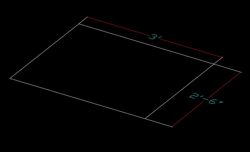
- Select the Extrude tool by typing EXT or Extrude in the command box
- Select the Rectangle and Extrude in an upwards direction
- Give Extrude height as 2'6" and press Enter
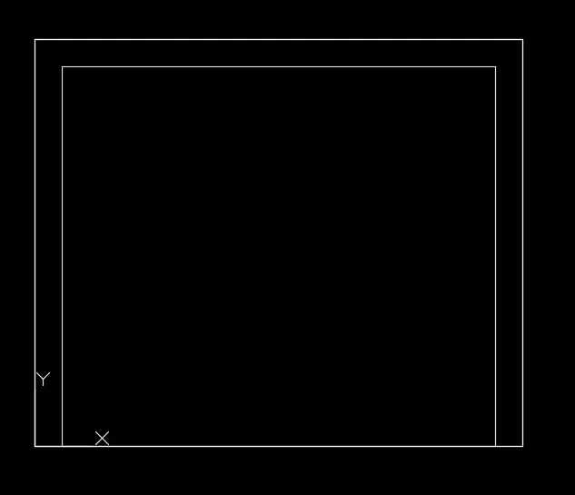
- Select the Front view from the UCS icon and provide X and Y coordinates in the front face Using UCS Command
- Select the Line command and draw a line of length 2" from the right side of the front view
- Select the Rectangle command and draw a rectangle of dimensions 2'8" and 2'4"
- Move the Rectangle to the line drawn earlier (i.e., 2" line from the right side of the face)
- After moving the rectangle, delete the previous line that we drew earlier
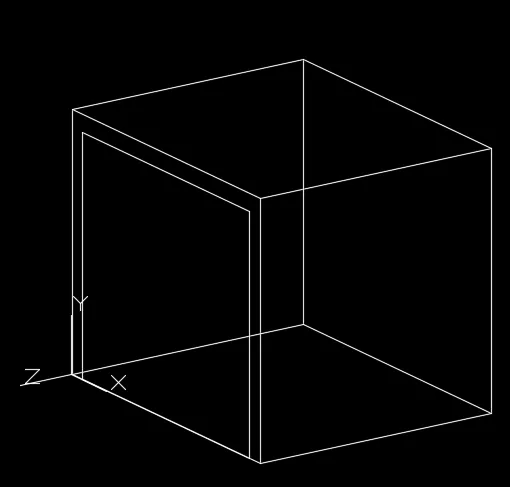
- Select the Extrude tool by typing EXT or Extrude in the command box
- Select the Interior rectangle that we drew earlier
- Extrude the rectangle with the height of 2'4" leaving 2" as thickness
- Select the Subtract tool by typing Subtract in the command box
- Select the Exterior Rectangle first and Press enter
- Then select the Interior rectangle and press enter to subtract the rectangle from the exterior one.
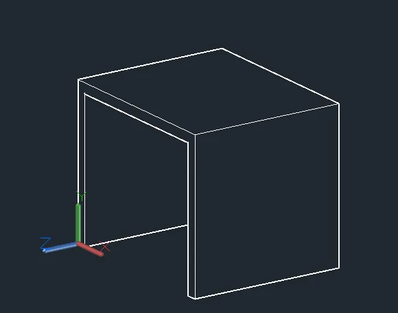
RESULT:-
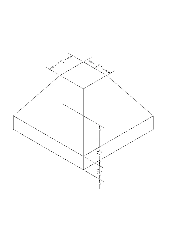
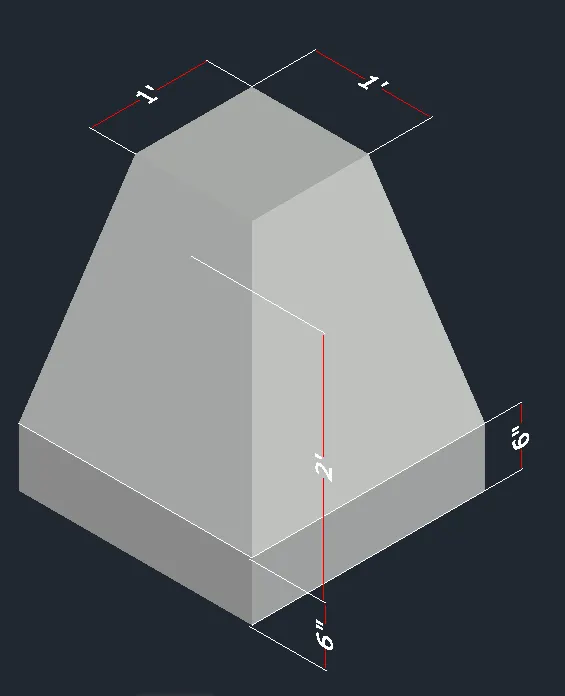
2. Create the 3d Model of an Isolated footing as shown in Figure.
COMMANDS USED:
- Units
- Limits
- UCS
- Rectangle
- Move
- Loft
- Extrude
PROCEDURE:-
- Go to the Top view using the UCS icon at the top right corner
- Select the Rectangle tool by typing REC or Rectangle in the command box
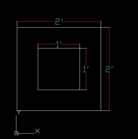
- Draw a rectangle with dimensions of the length of 2' and a width of 2'
- Similarly draw another rectangle with dimensions 1'×1' at the center concerning the previous one
- Go to the default 3D view using the UCS icon at the top right corner
- Select the Move tool and Select the Interior rectangle
- Move the rectangle upwards towards the Z direction at a distance of 2'
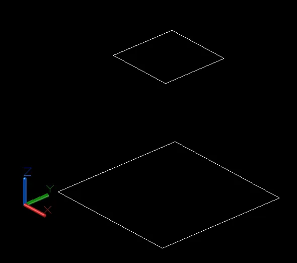
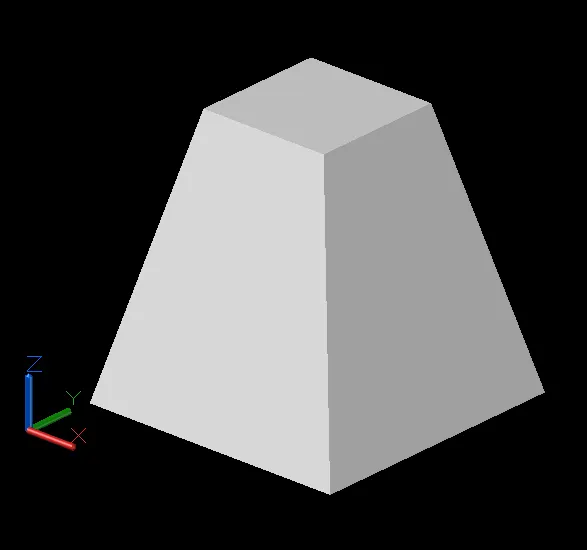
- Select the Loft tool from the ribbon tab or by typing Loft in the command box
- Select the Two rectangles and press enter to loft.
- Now go to the Top view again using the UCS icon
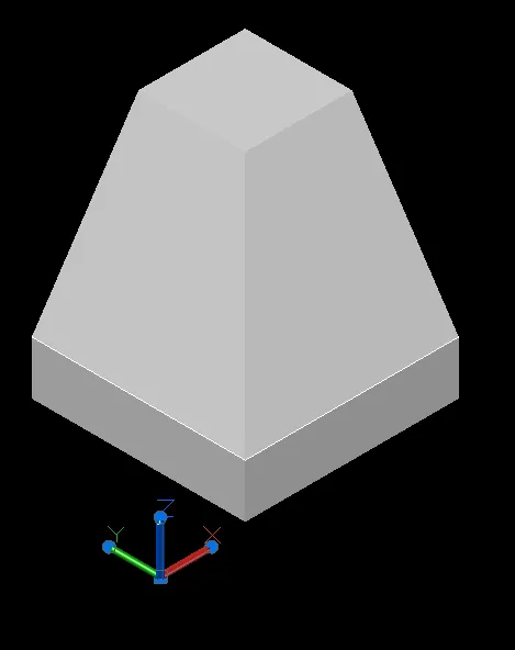
- Select the Rectangle tool and draw a similar rectangle of 2'×2' at the same position
- Go to the Default 3D view and Select the Extrude tool
- Extrude the previously created rectangle to the negative Z Direction with a height of 6" as shown in the figure below
RESULT:-
3. Create the 3D view of the AASTHO Type Girder.
COMMANDS USED:
- Units
- Limits
- UCS
- Line
- Sweep
- Region
- Dimensions
- Offset
- Layer
PROCEDURE:-
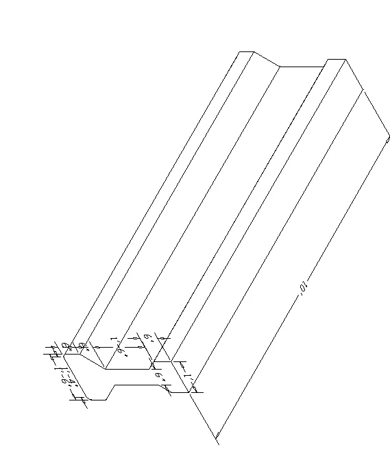
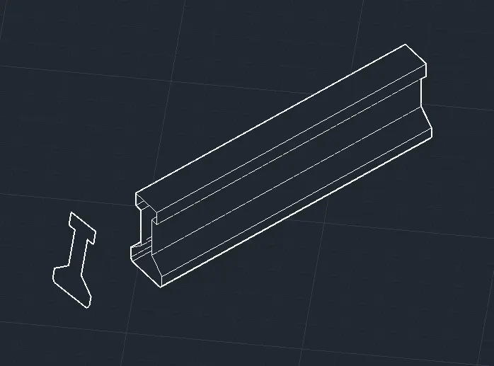
- Draw the line of 1' and in continued downward direction 6".
- Now offset the 6" line at the other side.
- then draw line of 3" from both side to make tube of 6"
- draw a middle tube of 1'6"
- then draw offset of 1" to 6" line downwards
- make that line 1'4" na joint to previous line of 6" to make a slanted lines
- then further 6" staright line from both the sides and make small slanted lines again and then join then at the bottom
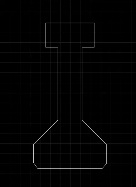
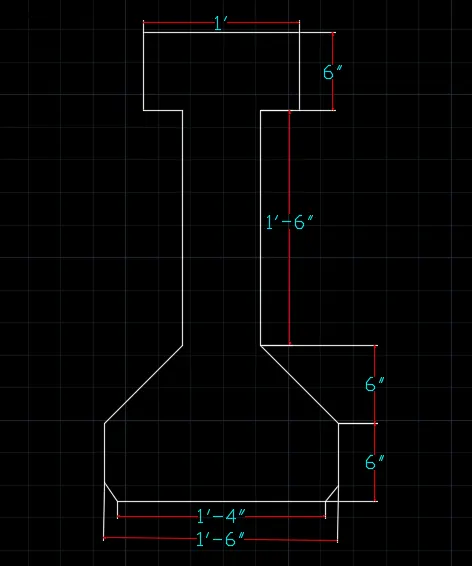
- Now go to the default 3D view using the UCS icon
- Select the Line command by typing L or Line in the command box
- Draw a line of length 10' in the XY plane as shown in the figure below
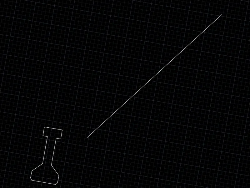
- Select the Sweep tool on the ribbon tab or by typing Sweep in the command box
- Select the object to sweep as the Astho Grider that we created earlier and press enter
- Now, select the path as Line that we created earlier and press Enter
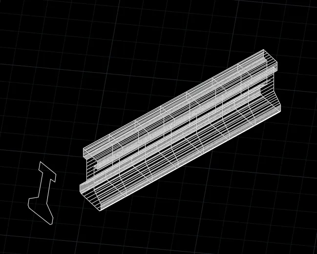
- After Creating the sweep from the front view of the girder, delete the previous one
- Now we can see the wireframe sketch of the AASTHO girder
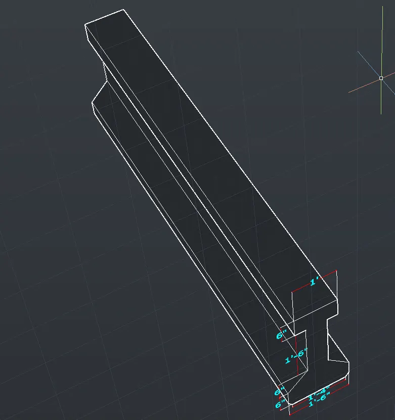
- The 3D model of the AASTHO type of girder has been sketched successfully as per the drawing
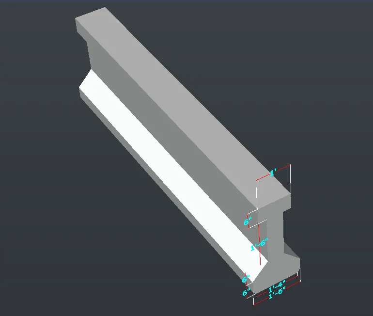
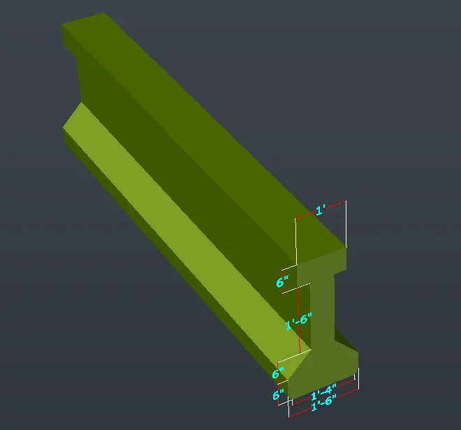
RESULT:-
- 3D view of AASTHO Type Girder is in image below.
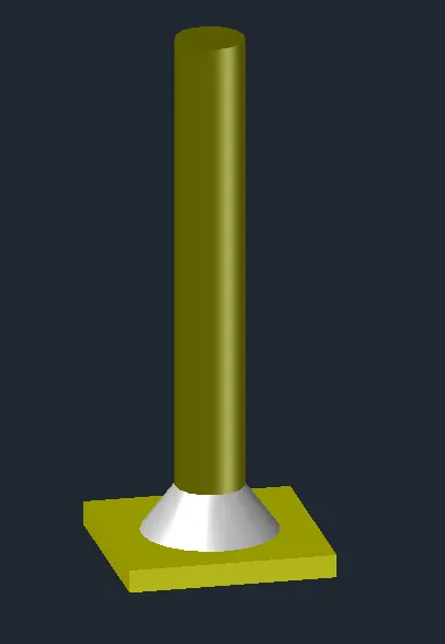
4. Create a 3d Model of a drop column with panel as shown in section and isometric view.
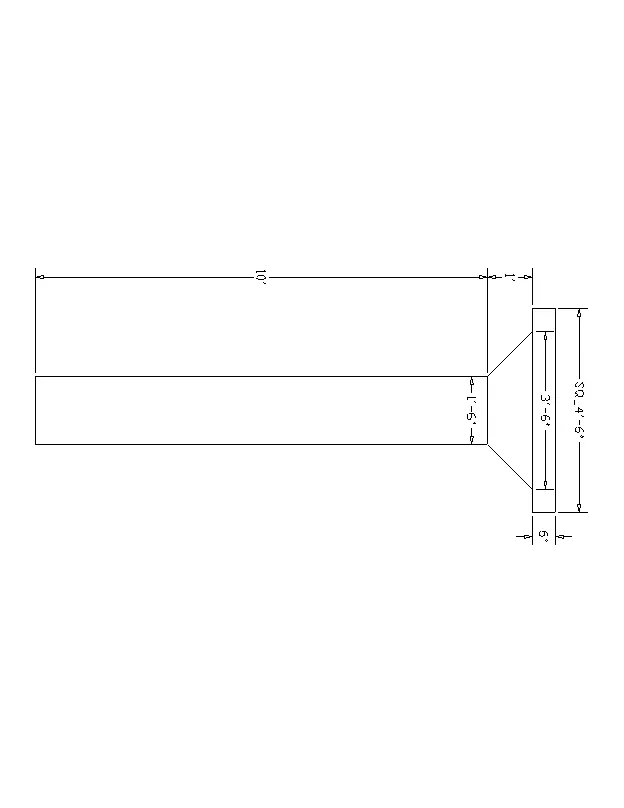
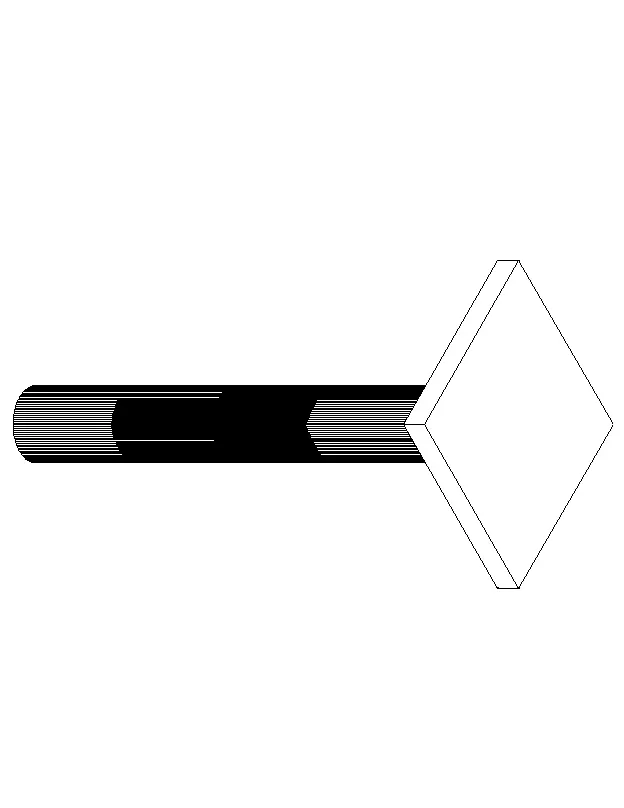
Procedure :-
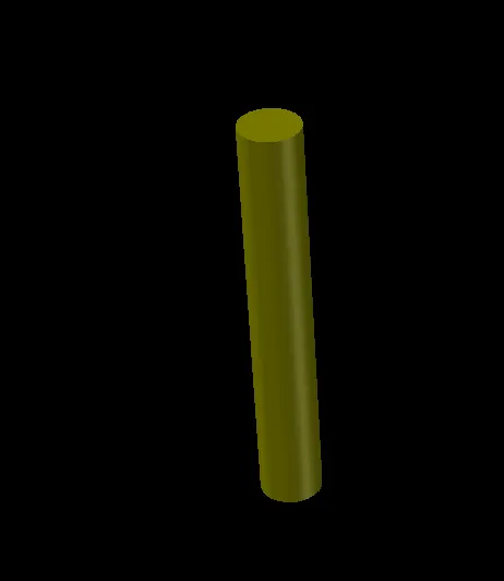
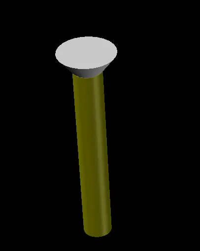
- Draw the circle of size 1'6".
- Extrude the circle with 10'.
- Now draw the corner.
- Select radius as 9".
- Selct te Top radius and type 1'6".
- Type height as 1'.
- Now place the frustum of cone on the circle that is extruded.
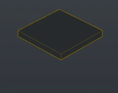
- Now draw the rectangle of size 4'6" X 4'6".
- Extrude the rectangle with height of 6".
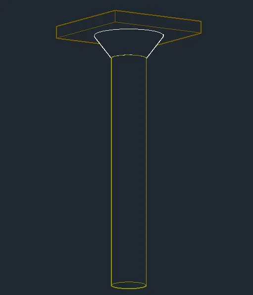
- Use the top vie to place the rectangle on cone.
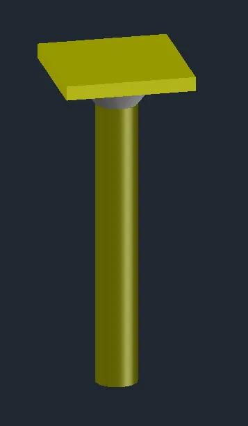
- Now place the rectangle on the cone that is place on the extruded circle.
RESULT:-
- 3d Model of a drop column with panel is in image below.
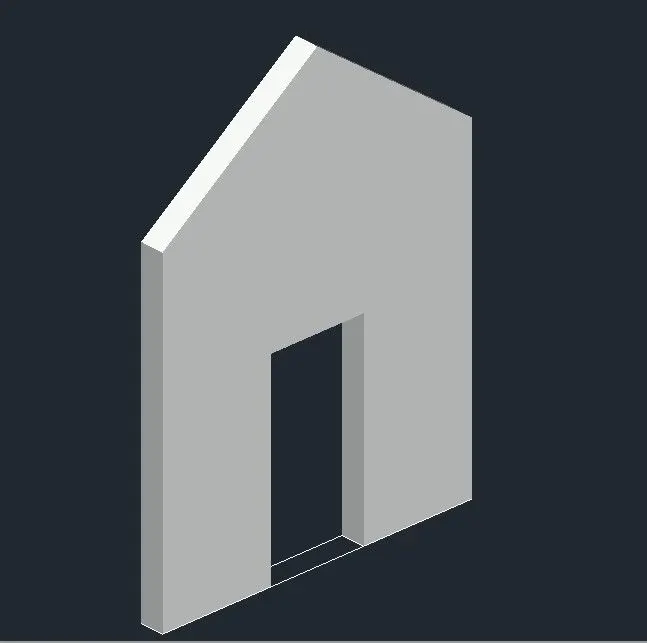
5. Create the 3d model of a wall as shown in Figure. Consider wall thickness as 9”.
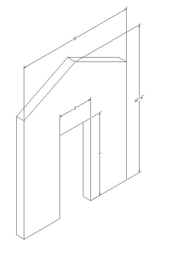
COMMANDS USED:
- Units
- Limits
- Rectangle
- Line
- Offset
- Extrude
- Move
- Join
- Trim
- Union
Procedure :-
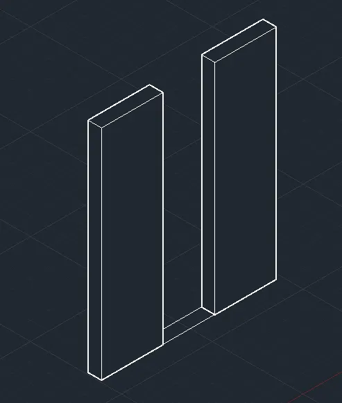
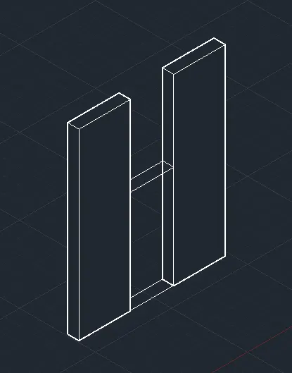
- Draw the rectangle of length 10' and width 9".
- Draw the line in the center parallel to 9" side,
- Offset the line with 1.5' both the side for door.
- Select the boundary at both the side.
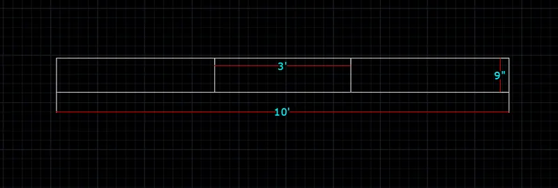
- Now Extrude the rigions with the height of 12'6".
- And Extrude the door with 7' height.
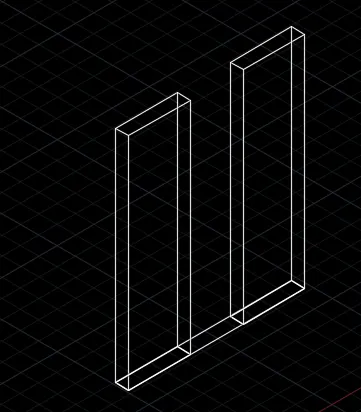
- From front view, draw the line in the center.
- Draw the slant line at both the last corener line.
- Select both the extruded boundaries.
- And move it to downward side with slant lines.
- Trim the Unwanted lines.
- Now select all 3 triangle lines and join it.
- Create the region of triangle.
- Extrude the triangle at back side.
- Now Union all the boundaries.
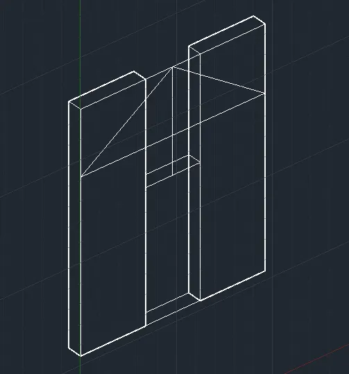
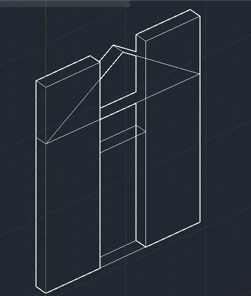
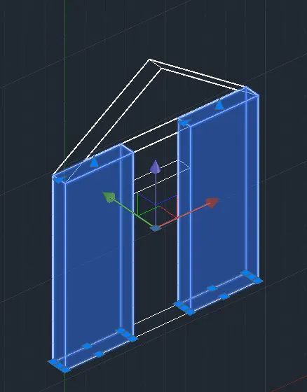
RESULT:-