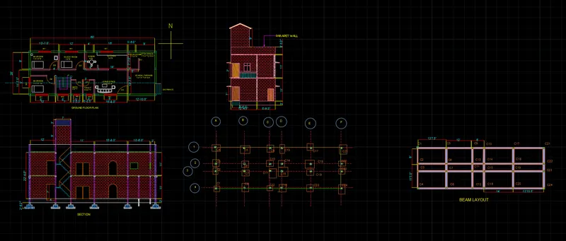
Project 1 _Creating an Architectural plan for the provided plot size and develop relevant basic structural drawings
AIM :- Design and Draft a layout of a residential building with the following details:
a. Plot Size: 60’x20’(18.3m x6m)
b. Orientation- Facing East
c. Develop the following: 1. Architectural Drawing (Floor Plan, Elevations, and Sections) 2. Structural Drawing (Column, Bean, Footing Plan)
Introduction: The desired drawings are created in AutoCAD using various tools. The procedure of drawing is explained in detail with diagrams of each step and the final result is given.
1.
AIM :-o Design and Draft a layout of a residential building with plot size (18.3 m x 6 m)
Commands Used:
- unit commnad
- limmax command
- zoom command
- XLINE command
- offset command
- Trim command
- Extend command
- ADC command
- Line command
- rectangle command
- linetype command
- arc command
- fillet command
- layer command
- leader command
- dimension command (dimlinear)
- text command
- copy command
- move command
Procedure:
step 1:
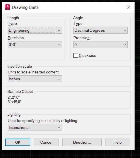
- In the command prompt involk the units and set it as Units = meters
- In the command prompt involk the limmax and set 100,100
- In the command prompt type limits >0,0
- In the command prompt type zoom >all
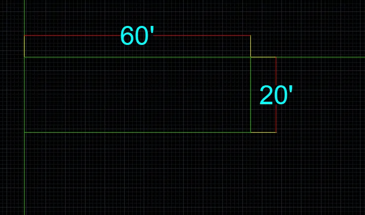
- go to layer property and select layer as wall and gives red colour to it
- then go for line command from ribbon or Line from dialog box
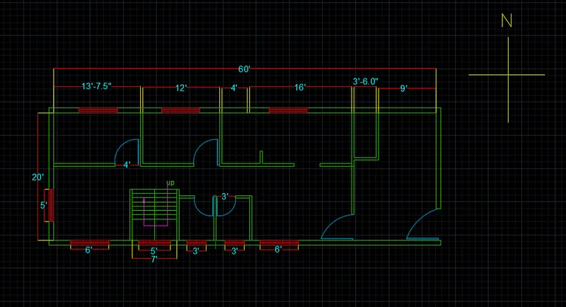
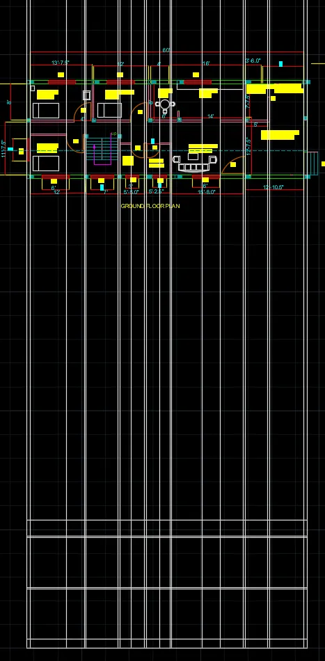
- now we have arrange the plan with residential amminities in 60'X20' plot size
- draw horizontal line of 60'
- and one verticle line with 20'
- then take OFFSET command and offset both line by 9" as wall thickness towrds inner side
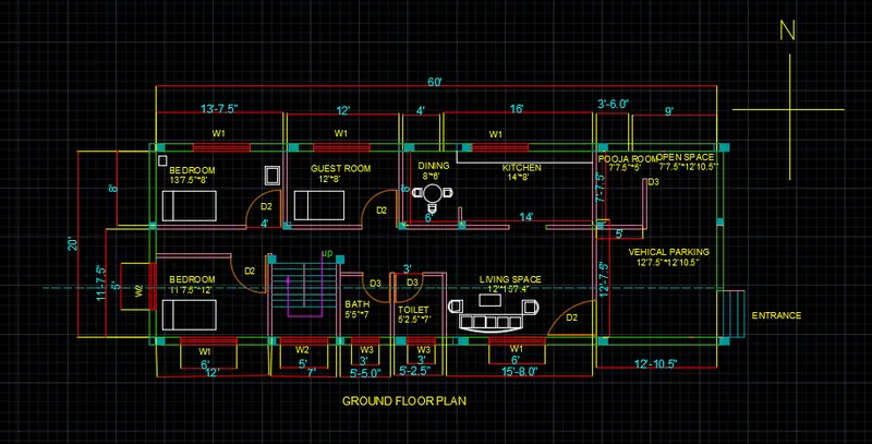
- then go to bottom line and offset from privious offset line as a distance of 13'7.5" for first room with 4.5" internal wall thickness
- now second offet from last line with 12' with 4.5" internal wall thickness
- then go left bottom portion and offset from internal line towards right at a distnce of 6' with 4.5" internal wall thickness
- then again offset for stair case at 7' with 4.5" wall thickness
- again take offset at a distance of 5'5" with 4.5" internal wall for toilet then offset of 5'2.5" with 4.5" internal wall for bath
- again offset of 15'8" with 4.5" external wall for Living Room
- now for parking area offset of 12'10.5" with 9" external wall,
- then again offset for bed room at 11'7.5" with 4.5" wall thickness
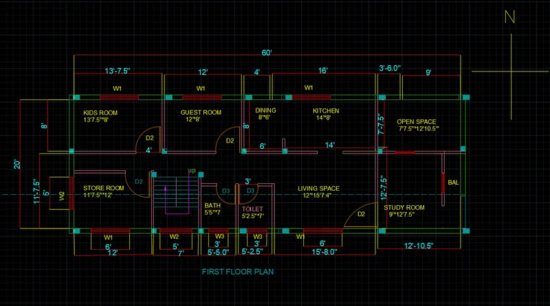
- again take offset at a distance of 3' with 4.5" internal wall for store room
- then offset of 20' with 4.5" internal wall for kitchen
- again offset of 5' with 9" external wall for pooja room
- now for open space offset of 7'7.5" with 9" external wall
- then go for door opening as shown in fig as per following dimensions
D1= 5'
D2=4"
D3= 3'6"
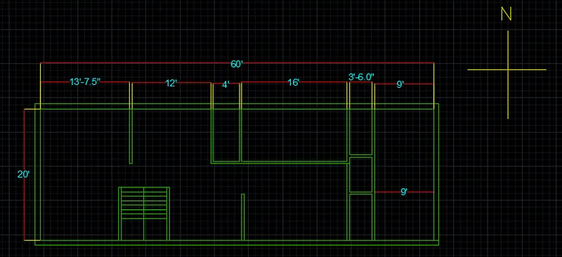
- In the command prompt type lines (to draw the windows )
- In the command prompt type arc (to draw the doors )
- The architectural plan is completed
- In the ribbon bar type Annotate to text the dimensions
FINAL ARCHITECTURAL PLANS OF GROUND AND FIRST FLOOR ARE AS BELOW;
ELEVATION OF FLOOR PLAN:-
- Draw a projection with respect to floor plan
- Using the commands Line, polyline, offset, fillet, trim and hatch, I have created the FRONT ELEVATION for the building.
- The Stair room windows are 4'x3'6"
- The Main door+glass window dimensions are 4' x 7'.
- And, using DText command, the text and name is given.
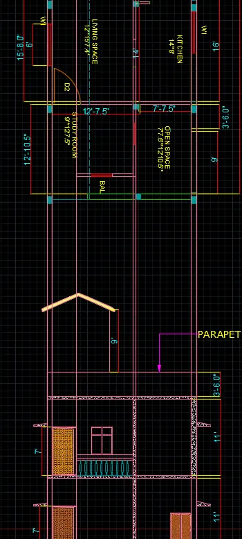
- draw a door in such way that take projections from te plan
- using offseet, line, trim commnad draw a door with specification
- give the hatch to the door for good asthetic
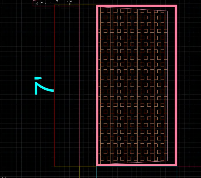
. Doors and Windows
- Doors and windows for elevation are similar to those added in section 2-2 view
- Door of first is half visible because of the parapet wall as shown in figure
- Curved Window along the inner staircase is added at a height of 4’ from the roof bottom as shown in figure
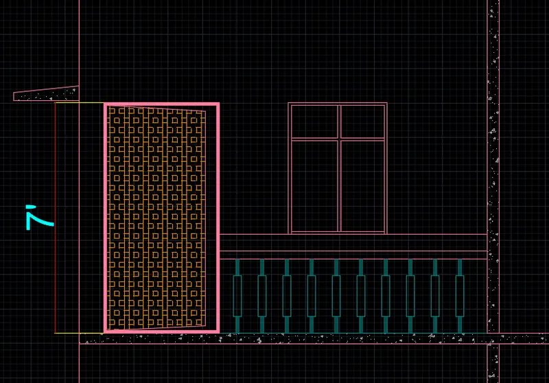
FRONT ELEVATION OF ARCHITECTURAL PLAN:-
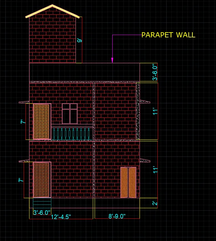
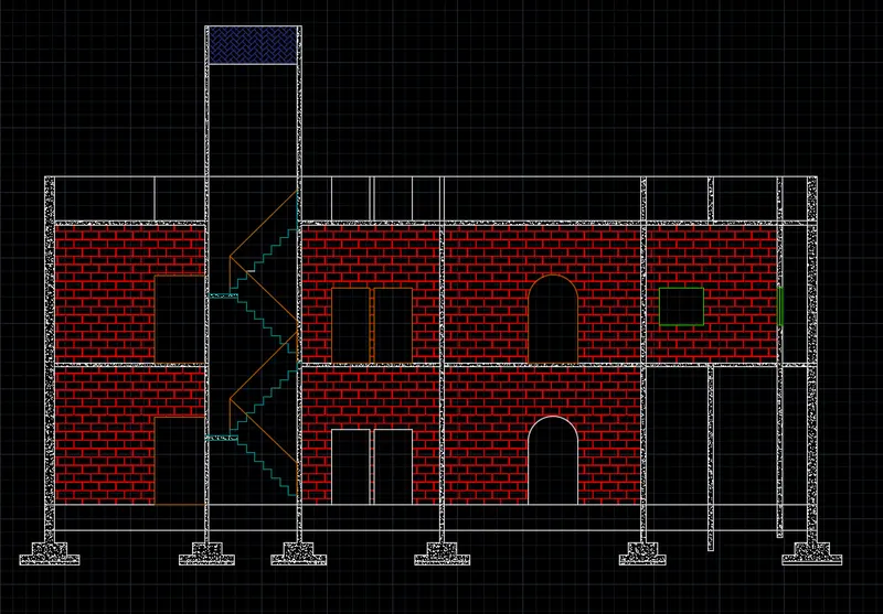
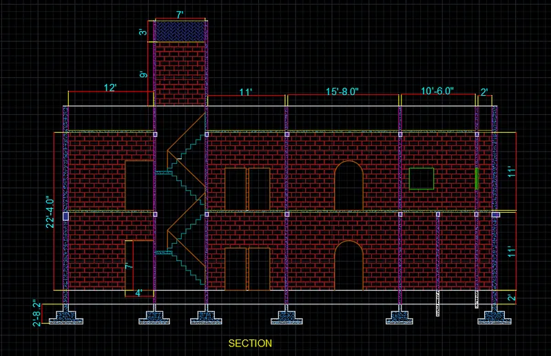
SECTION A-A OF FLOOR PLAN:-
- Draw a projection with respect to floor plan
- Using the commands Line, polyline, offset, fillet, trim and hatch, I have created the FRONT ELEVATION for the building.
- The Stair room windows are 4'x3'6"
- The Main door+glass window dimensions are 4' x 7'.
- And, using DText command, the text and name is given.
- Give hatch whrever require and good asthetic purpose
STRUCTURAL DRAWINGS:-
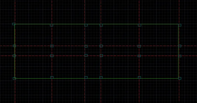
- Using the CENTERLINE LineType, the grid lines are provided.
- Using the DIM-LIN and DIM-CONTINUE command, the dimensions between the grid lines are mentioned.
- Also using the DIM-LIN command, the column positions in the footing is mentioned.
- Using DText command, the Grid names and title is given.
- For better visibility, I have provided colors for grid lines and dimensions between grid lines.
- Go to LAYER properties, except COLUMNS layer lock all the other layers.
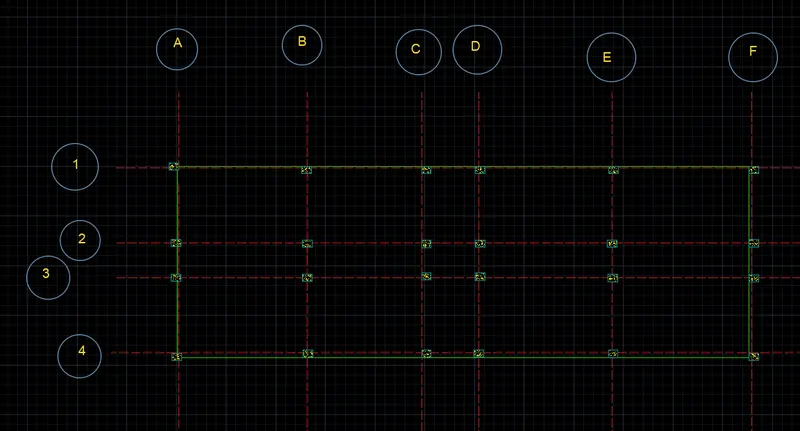
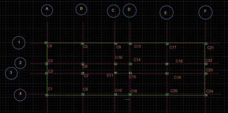
- Using the line command, the square footing of size 4'x4' is provided for all the columns except for staircase column where footing of size 3'x3' is provided.
- Using the CENTERLINE LineType, the grid lines are provided.
- Using the DIM-LIN and DIM-CONTINUE command, the dimensions between the grid lines are mentioned.
- Also using the DIM-LIN command, the column positions in the footing is mentioned.
- Using DText command, the Grid names and title is given.
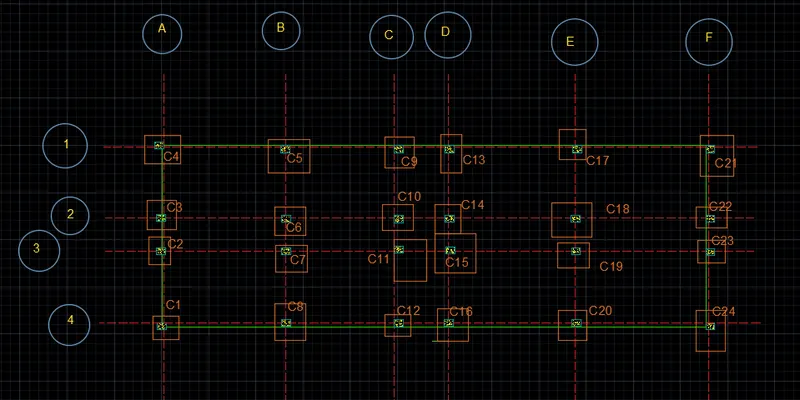
- Go to LAYER properties, except COLUMNS layer lock all the other layers.
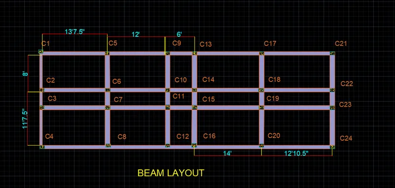
- Now, using Copy command, copy all the columns, plot boundary and paste it parallely.
- Using the line command, connect the columns with beams of 9" width.
- Using the DIM-LIN and DIM-CONTINUE command, the Center-to-Center distance between each beams are mentioned.
- Using the DText command, the beam names and title of the layout is mentioned.
FINAL RESULT: